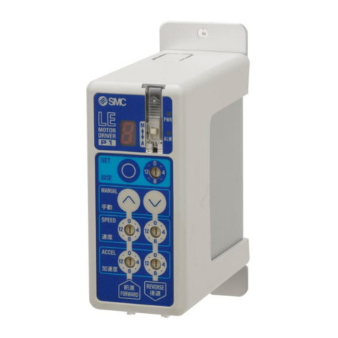
SMC Corporation LECP1 series User manual

No. JXC※-OMU0029-A
PRODUCT NAME
Programless controller
Step motor (servo 24 VDC)
MODEL / Series / Product Number
LECP1 Series

- 1 -
No. JXC※-OMU0029-A
Contents
1. Safety Instructions .........................................................................................................4
2. Product Outline...............................................................................................................6
2.1 Product features........................................................................................................6
2.2 Product configuration ..............................................................................................7
2.3 How to Order .............................................................................................................8
2.4 Option.........................................................................................................................9
(1) Actuator cable (5m or less)...................................................................................9
(2) Actuator cable (8-20m) ..........................................................................................9
(3) Actuator cable for with lock and sensor (5m or less)......................................10
(4) Actuator cable for with lock and sensor (8-20m) .............................................10
2.5 Startup Procedures................................................................................................. 11
(1) Confirmation of the package content................................................................ 11
(2) Installation ............................................................................................................ 11
(3) Wiring and connection ........................................................................................ 11
(4) Confirmation of the power ON alarm.................................................................12
(5) Data (Operation pattern) setting.........................................................................12
(6) Test run .................................................................................................................12
3. Product Specifications.................................................................................................13
3.1 Basic specifications ...............................................................................................13
3.2 Parts description.....................................................................................................14
3.3 Outside dimension diagramm ...............................................................................15
3.4 How to install...........................................................................................................16
(1) How to install........................................................................................................16
(2) Grounding cable connection..............................................................................16
(3) Installation location .............................................................................................17
4. External Wiring Diagram..............................................................................................18
4.1 CN1: Power supply cable.......................................................................................18
4.2 CN2: Motor power connector and CN3: Encoder connector .............................18
4.3 CN4: Parallel I/O connector....................................................................................18
5. CN1: Power supply cable.............................................................................................19
5.1 Power supply cable specifications.......................................................................19
5.2 Wiring of power supply cable................................................................................19
(1) Wiring of the power supply.................................................................................19
(2) Wiring of the lock release ...................................................................................20
(3) Stop the power supply for the motor.................................................................20

- 2 -
No. JXC※-OMU0029-A
6. CN4: Parallel l/O Connector ........................................................................................22
6.1 Parallel I/O specifications ......................................................................................22
6.2 Parallel I/O type (NPN / PNP type).........................................................................22
(1) Parallel I/O input circuit (same for both NPN and PNP type)..........................22
(2) Parallel I/O output circuit ....................................................................................22
6.3 The parallel I/O signal is detailed..........................................................................23
(1) Parallel I/O cable (LEC-CK4-□)............................................................................23
(2) Derails of input / Output signal ..........................................................................23
(3) The change of I/O output signal.........................................................................24
6.4 Parallel I/O Wiring Example ...................................................................................25
7. Setting method..............................................................................................................26
7.1 Setting procedure ...................................................................................................27
(1) Supply of power...................................................................................................27
(2) Changes to Manual mode ...................................................................................27
(3) Return to origin....................................................................................................27
(4) Setting of position and operation method ........................................................28
(5) Test run .................................................................................................................34
(6) Setting of Speed and Acceleration ....................................................................34
(7) Completion of setting..........................................................................................34
7.2 Setting parameters .................................................................................................35
7.3 Controller modes ....................................................................................................38
(A) Before return to origin........................................................................................39
(B) Auto mode after return to origin........................................................................40
(C) Manual mode after retun to origin.....................................................................41
7.4 Test function............................................................................................................42
8. Operations.....................................................................................................................43
8.1 Return to origin.......................................................................................................43
8.2 Positioning operation.............................................................................................43
8.3 Pushing operation...................................................................................................44
(1) Successful pushing operation ...........................................................................44
(2) Pushing operation is failed (pushing the air)...................................................44
(3) Movement of the work piece after the completion of the pushing
operation .........................................................................................................45
8.4 Jog operation / inching operation.........................................................................46
8.5 Servo ON..................................................................................................................47
8.6 Response time for the controller input signal.....................................................47
8.7 LED display in auto mode......................................................................................48

- 3 -
No. JXC※-OMU0029-A
9. Operation instruction...................................................................................................49
9.1 Positioning / Return to origin................................................................................49
9.2 Pushing operation...................................................................................................50
9.3 Stoppage during operation....................................................................................51
9.4 Alarm generation and reset ...................................................................................52
10. Initial setting value per electric actuator .................................................................53
10.1 Initial setting value of LEF series........................................................................53
10.2 Initial setting value of LEH series .......................................................................56
10.3 Initial setting value of LES,LESH series ...........................................................59
10.4 Initial setting value of LEY,LEYG series...........................................................61
10.5 Initial setting value of LER series .......................................................................64
10.6 Initial setting value of LEPY,LEPS series.........................................................65
10.7 Initial setting value of LEL series........................................................................66
10.8 Initial setting value of LEM series.......................................................................67
11. Alarm Detection ..........................................................................................................68
11.1 Alarm group output...............................................................................................68
11.2 Alarm details..........................................................................................................69
12. Wiring of cables / Common precautions .................................................................72
13. Electric actuators / Common precautions...............................................................73
13.1 Design and selection............................................................................................73
13.2 Mounting................................................................................................................74
13.3 Precautions for Use..............................................................................................74
13.4 Operating environment ........................................................................................76
13.5 Maintenance ..........................................................................................................76
13.6 Precautions for electric actuator with lock........................................................77
14.
Controller and its peripheral devices / Specific product precautions
.............................78
14.1 Design and selection............................................................................................78
14.2 Handling.................................................................................................................78
14.3 Installation .............................................................................................................79
14.4 Wiring.....................................................................................................................79
14.5 Power supply.........................................................................................................80
14.6 Grounding..............................................................................................................80
14.7 Maintenace.............................................................................................................80
15. Troubleshooting..........................................................................................................81

- 4 -
No. JXC※-OMU0029-A
LECP1 Series / Controller
1. Safety Instructions
These safety instructions are intended to prevent hazardous situations and/or equipment damage.
These instructions indicate the level of potential hazard with the labels of “Caution,” “Warning” or
“Danger.”
They are all important notes for safety and must be followed in addition to International Standards
(ISO/IEC)*1), and other safety regulations.
*1) ISO 4414: Pneumatic fluid power -- General rules relating to systems.
ISO 4413: Hydraulic fluid power -- General rules relating to systems.
IEC 60204-1: Safety of machinery -- Electrical equipment of machines. (Part 1: General
requirements)
ISO 10218-1992: Manipulating industrial robots -Safety.
etc.
Caution
Caution indicates a hazard with a low level of risk which, if not avoided, could result in minor or
moderate injury.
Warning
Warning indicates a hazard with a medium level of risk which, if not avoided, could result in
death or serious injury.
Danger
Danger indicates a hazard with a high level of risk which, if not avoided, will result in death or
serious injury.
Warning
1. The compatibility of the product is the responsibility of the person who designs the equipment or
decides its specifications.
Since the product specified here is used under various operating conditions, its compatibility with specific
equipment must be decided by the person who designs the equipment or decides its specifications based on
necessary analysis and test results.
The expected performance and safety assurance of the equipment will be the responsibility of the person who
has determined its compatibility with the product.
This person should also continuously review all specifications of the product referring to its latest catalog
information, with a view to giving due consideration to any possibility of equipment failure when configuring the
equipment.
2. Only personnel with appropriate training should operate machinery and equipment.
The product specified here may become unsafe if handled incorrectly.
The assembly, operation and maintenance of machines or equipment including our products must be
performed by an operator who is appropriately trained and experienced.
3. Do not service or attempt to remove product and machinery/equipment until safety is confirmed.
1.The inspection and maintenance of machinery/equipment should only be performed after measures to
prevent falling or runaway of the driven objects have been confirmed.
2.When the product is to be removed, confirm that the safety measures as mentioned above are implemented
and the power from any appropriate source is cut, and read and understand the specific product precautions
of all relevant products carefully.
3.Before machinery/equipment is restarted, take measures to prevent unexpected operation and malfunction
4. Contact SMC beforehand and take special consideration of safety measures if the product is to
be used in any of the following conditions.
1.Conditions and environments outside of the given specifications, or use outdoors or in a place exposed to
direct sunlight.
2.Installation on equipment in conjunction with atomic energy, railways, air navigation, space, shipping,
vehicles, military, medical treatment, combustion and recreation, or equipment in contact with food and
beverages, emergency stop circuits, clutch and brake circuits in press applications, safety equipment or
other applications unsuitable for the standard specifications described in the product catalog.
3.An application which could have negative effects on people, property, or animals requiring special safety
analysis.
4.Use in an interlock circuit, which requires the provision of double interlock for possible failure by using a
mechanical protective function, and periodical checks to confirm proper operation.

- 5 -
No. JXC※-OMU0029-A
LECP1 Series / Controller
1. Safety Instructions
Caution
The product is provided for use in manufacturing industries.
The product herein described is basically provided for peaceful use in manufacturing industries.
If considering using the product in other industries, consult SMC beforehand and exchange specifications
or a contract if necessary.
If anything is unclear, contact your nearest sales branch.
Limited warranty and Disclaimer/Compliance Requirements
The product used is subject to the following “Limited warranty and Disclaimer” and “Compliance
Requirements”.
Read and accept them before using the product.
Limited warranty and Disclaimer
1.The warranty period of the product is 1 year in service or 1.5 years after the product is delivered,
whichever is first.2)
Also, the product may have specified durability, running distance or replacement parts. Please
consult your nearest sales branch.
2.For any failure or damage reported within the warranty period which is clearly our responsibility,
a replacement product or necessary parts will be provided.
This limited warranty applies only to our product independently, and not to any other damage
incurred due to the failure of the product.
3.Prior to using SMC products, please read and understand the warranty terms and disclaimers
noted in the specified catalog for the particular products.
*2) Vacuum pads are excluded from this 1 year warranty.
A vacuum pad is a consumable part, so it is warranted for a year after it is delivered.
Also, even within the warranty period, the wear of a product due to the use of the vacuum pad
or failure due to the deterioration of rubber material are not covered by the limited warranty.
Compliance Requirements
1.The use of SMC products with production equipment for the manufacture of weapons of mass
destruction (WMD) or any other weapon is strictly prohibited.
2.The exports of SMC products or technology from one country to another are governed by the
relevant security laws and regulations of the countries involved in the transaction. Prior to the
shipment of a SMC product to another country, assure that all local rules governing that export
are known and followed.
Caution
SMC products are not intended for use as instruments for legal metrology.
Measurement instruments that SMC manufactures or sells have not been qualified by type approval tests
relevant to the metrology (measurement) laws of each country.
Therefore, SMC products cannot be used for business or certification ordained by the metrology
(measurement) laws of each country.

- 6 -
No. JXC※-OMU0029-A
2. Product Outline
2.1 Product features
The followings are the main functions of this controller:
Electric actuator Control
Positioning operation and Pushing operation, at a specific speed and force, of the electric
actuator are possible by controlling the Step motor (24 VDC servo).
Operation and settings are available with the controller.
Settings can be altered and operation can be run from the controller. Adjustments of the position,
speed, acceleration and test runs are available without the teaching box, PC, and PLC.
Specified force operation
Control the pushing force (or the pressing force) of the electric actuator.
Power supply separation input
The power supply is separated into the drive power and the control power. Therefore, even when
the drive power is off, if the control power is on, the position information from the encoder will be
maintained and the serial communication and parallel I/O control are still available.
Automatic sequence function of the return to origin position
Return to origin position is available through I/O signal combination.
Alarm detection function
Automatically detect the abnormal conditions and output the appropriate alarm signal via the
serial interface and parallel I/O.
14 points positioning / pushing is available
Through the combination of parallel I/O inputs, 14 points (position number 1 to 14(E)) of
positioning / pushing are available. The speed and acceleration of the positioning can be set by
the switch for each operating direction.
Data input method
Parameter settings, test runs, and alarm resets can be performed by the controller.
Caution
When the device is set up or failure occurs, please refer to the operation manual of the actuator as well
as this operation manual.
Keep this operation manual accessible so it can be referred to when necessary.

- 7 -
No. JXC※-OMU0029-A
PLC
Input / output signal
power supply
24 VDC
2.2 Product configuration
The product configuration of this controller is as follows.
●Electric actuator *1)
*1) These items are included when ordered using the part number for an electric actuator set.
*2) When conformity to UL is required, the electric actuator and controller should be used with a
UL1310 Class 2 power supply.
Warning
Refer to “4. External Connection for wiring”
Refer to “12. Precautions for wiring and cables”when handling the wiring and cables.
To CN4
To CN3
To CN2
To CN1
●Controller
●Power supply cable
Part No: LEC-CK1-1
I/O cable *1)
Part No: LEC-CK4-□
●Actuator cable *1)
Part No: LE-CP-□-S
LE-CP-□-B-S
(Standard cable)
LE-CP-□
LE-CP-□-B
(Robotic type cable)
Controller power supply
24 VDC

- 8 -
No. JXC※-OMU0029-A
2.3 How to Order
The part number construction for this product is as follows:
Controller
LECP1N□□-□
Controller Electric actuator model
Compatible
Number of step data
Parallel I/O type Option
I/O cable length
1.5 m power cable is included
Electric actuator+Controller
LEHZ10LK2-4AF-R11N□□
Electric actuator type Option
Compile the product number while referring to the How to Order
section in the electric actuator catalogue. Please refer to the table
below for the corresponding electric actuator. I/O cable length *1)
Controller
*1) An I/O cable cannot be specified for an actuator without a controller.
The LECP6 series I/O cable cannot be used because the specifications are different.
Caution
Single controllers are also shipped after setting the electric actuator specification parameters.
Check that the combination of the controller and the electric actuator is correct before use.
Example: For LEHZ10LK2-4AF-R11N1,
specify LEHZ10LK2-4.
(Enter from the electric actuator part number
“LE”to “stroke / rotating angle”)
Applicable electric actuators
Electric gripper:LEH Series
Electric slide table:LES Series
Electric actuator / Rod type:LEY Series
Electric actuator / Slider type:LEF Series
Electric actuator / Low profile slider type:LEM Series
Electric actuator / Rotary type:LER Series
Electric actuator / Guide rod Slider:LEL Series
Electric actuator / Miniature type:LEP Series
Nil
No controller*
1N
With programless controller (NPN)
1P
With programless controller (PNP)
Nil
None
1
1.5 m
3
3 m
5
5 m
P
Stepmotor (Servo /24VDC)
1
14points(Programless)
N
NPN type
P
PNP type
Nil
None
1
1.5 m
3
3 m
5
5 m
Nil
Screw mounting
D
DIN rail mounting

- 9 -
No. JXC※-OMU0029-A
2.4 Option
(1) Actuator cable (5m or less)
LE-CP-□-□
Cable length (L)
Actuator cable type
Electric actuator side
(2) Actuator cable (8-20m)
LE-CP-□
Cable length (L)
*1) Produced upon receipt of
order.
Only Robotic type cable
can be selected.
Electric actuator side
signal
Terminal no.
A
B-1
A
A-1
B
B-2
B
A-2
COM-A/COM
B-3
COM-B/ -
A-3
Vcc
B-4
GND
A-4
A
B-5
A
A-5
B
B-6
B
A-6
signal
Terminal no.
A
B-1
A
A-1
B
B-2
B
A-2
COM-A/ COM
B-3
COM-B / -
A-3
Vcc
B-4
GND
A-4
A
B-5
A
A-5
B
B-6
B
A-6
Cable color
Terminal no.
Brown
2
Red
1
Orange
6
Yellow
5
Green
3
Blue
4
Cable color
Terminal no.
Brown
12
Black
13
Red
7
Black
6
Orange
9
Black
8
-
3
Shield
①
②
③
8
8m *1)
A
10m *1)
B
15m *1)
C
20m *1)
Controller side
1
1.5m
3
3m
5
5m
Shield
①
②
③
Cable color
Terminal no.
Brown
2
Red
1
Orange
6
Yellow
5
Green
3
Blue
4
Cable color
Terminal no.
Brown
12
Black
13
Red
7
Black
6
Orange
9
Black
8
-
3
Nil
Robotic type cable
S
Standard cable
Controller side

- 10 -
No. JXC※-OMU0029-A
(3) Actuator cable for with lock and sensor (5m or less)
LE-CP- □-B- □
Cable length (L)
Actuator cable type
Electric actuator side
(4) Actuator cable for with lock and sensor (8-20m)
LE-CP-□-B
Cable length (L)
*1) Produced upon receipt of
order
Only “Robotic type cable”
can be selected.
Electric actuator side
signal
Terminal no.
A
B-1
A
A-1
B
B-2
B
A-2
COM-A/ COM
B-3
COM-B / -
A-3
Vcc
B-4
GND
A-4
A
B-5
A
A-5
B
B-6
B
A-6
signal
Terminal no.
A
B-1
A
A-1
B
B-2
B
A-2
COM-A/COM
B-3
COM-B / -
A-3
Vcc
B-4
GND
A-4
A
B-5
A
A-5
B
B-6
B
A-6
Cable color
Terminal no.
Brown
2
Red
1
Orange
6
Yellow
5
Green
3
Blue
4
Cable color
Terminal no.
Brown
12
Black
13
Red
7
Black
6
Orange
9
Black
8
-
3
Red
4
Black
5
Brown
1
Blue
2
Shield
①
②
③
1
1.5m
3
3m
5
5m
signal
Terminal no.
Lock
(+)
B-1
Lock
(-)
A-1
Sensor
(+)
B-3
Sensor
(-)
A-3
①
②
Controller side
Cable color
Terminal no.
Brown
2
Red
1
Orange
6
Yellow
5
Green
3
Blue
4
Cable color
Terminal no.
Brown
12
Black
13
Red
7
Black
6
Orange
9
Black
8
-
3
Red
4
Black
5
Brown
1
Blue
2
Shield
③
signal
Terminal no.
Lock
(+)
B-1
Lock
(-)
A-1
Sensor
(+)
B-3
Sensor
(-)
A-3
④
Controller side
8
8m *1)
A
10m *1)
B
15m *1)
C
20m *1)
④
Nil
Robotic type cable
S
Standard cable

- 11 -
No. JXC※-OMU0029-A
Controller Power supply cable
I/O cable
2.5 Startup Procedures
Be sure to check the procedure below before use.
(1) Confirmation of the package content
After unpacking everything, check the description on the label to identify the controller and the number
of accessories. If any parts are missing or damaged, please contact your distributor.
1) Included in the package only when the
I/O cable length is specified.
【Option】
●Actuator cable
(2) Installation
Please refer to the “3.4 How to install”
(3) Wiring and connection
Connect cables, etc. to the connector (CN1 to CN4) of the controller.
Please refer to the “4 External Wiring Diagram” for the wiring of the connectors.
Connector
Item
Quantity
Controller (LECP1□□-□)
1 unit
Power supply cable (LEC-CK1-1)
1 piece
I/O cable (LEC-CK4-□)*1)
1 piece
Actuator cable

- 12 -
No. JXC※-OMU0029-A
(4) Confirmation of the power ON alarm
Supply power 24VDC.
Function
LED turns on
Status
PWR
Green LED is ON
Servo is turned on
Green LED is flashing
Servo is turned off
ALM
Red LED is ON
Alarm is generated
Under normal conditions, the LED [PWR] on the front of the controller changes from a flashing green
to a solid light.
The servo will be turned ON if the conditions are normal.
When the LED [ALM] on the front of the controller lights up red, it indicates an alarm.
Caution
If an alarm is generated, check the content of the alarm using the 7-segment LED on the controller or
I/O output, and eliminate the cause while referring to “11. Alarm Detection”.
(5) Data (Operation pattern) setting
Set the stop position, speed and acceleration per operating direction with the buttons and switches on
the controller.
Operations other than position setting, Jog / inching can be performed after returning to origin position.
Refer to “7. Setting method”for the details of settings.
(6) Test run
Test runs can be performed using the buttons on the controller or by using I/O signals.
Refer to “6.3 The parallel I/O signal is detailed” and “7.1 Setting procedure” for details.
Controller

- 13 -
No. JXC※-OMU0029-A
3. Product Specifications
3.1 Basic specifications
The basic specifications of this controller are as follows:
Item
Specifications
Compatible motor
Unipolar winding method 2-Phase HB step motor
Power supply *1) *2)
Power voltage: 24 VDC +/-10% *2)
When conformity to UL is required, use UL1310 compliant Class 2
power supply unit for direct current.
Parallel input
6 inputs (photo-coupler isolation)
Parallel output
6 outputs (photo-coupler isolation)
Stop points
14 points (Location number 1 to 14(E))
Compatible encoder
Incremental A / B phase (800 pulse / rotation)
Memory
EEPROM
LED indicator
2 of LED’s (green and red)
7-segment LED display *3)
1 digit, 7-segment display (red)
Figures are expressed in hexadecimal (10 to 15 in decimal number
are expressed as A to F)
Lock control
Forced-lock release terminal (Applicable to non -magnetizing lock.)
Cable length
I/O cable: 5m or less
Actuator cable: 20m or less
Cooling system
Natural air cooling
Operating temperature range
0 to 40oC (No freezing)
Operating humidity range
90%RH or less (No condensation)
Storage temperature range
-10 to 60oC (No freezing)
Storage humidity range
90%RH or less (No condensation)
Insulation resistance
Between external terminals and case
50 MΩ(500VDC)
Mass
130 g (screw mount type)
150 g (DIN rail mount type)
*1) Do not use the inrush current suppression type power supply for the controller power (24VDC).
*2) The power consumption changes depending on the electric actuator model.
Please refer to the specifications of the electric actuator for more details.
*3) "10" to "15" in decimal number are displayed as follows in the 7-segment LED.
Decimal display 10 11 12 13 14 15
Hexadecimal display A b c d E F

- 14 -
No. JXC※-OMU0029-A
3.2 Parts description
The detailed descriptions of each part are as follows:
No.
Display
Description
Details
(a)
PWR
Power
supply LED
Power supply ON / Servo ON: Green solid light
Power supply ON / Servo OFF: Green flashes
(b)
ALM
Alarm LED
Power supply ON / With alarm: Red solid light
Power supply ON / Parameter setting: Red
flashes
(c)
―
Cover
Mode switch switching protection.
(Close the cover after changing swich).
(d)
―
FG
Frame ground
(Tighten the bolt with the nut when mounting the
controller. Connect the grounding wire.)
(e)
―
Mode switch
Swich the mode between manual and auto.
(f)
―
7-segment
LED
Auto mode / Without alarm:
Indicates the position number which is instructed
by ON/OFF of IN0 to IN3 of the CN4 parallel I/O.
(During command operation: Flashing /
Instruction command completed: ON)
Auto mode / With alarm:
Indicates Alarm Group.
Manual mode: Indicates that content may vary
depending on the operating
function.
(g)
SET
Set button
Determines the settings and gives a command to
operate in manual mode.
(h)
―
Position
switch
Assigns the position to drive (1 to 14) and the
origin (15).
(i)
MANUAL
Forward
button
Performs forward Jog and inching.
(j)
Reverse
button
Performs reverse Jog and inching.
(k)
SPEED
Forward
speed switch
16 forward speeds are available. *1)
(l)
Reverse
speed switch
16 reverse speeds are available. *1)
(m)
ACCEL
Forward
acceleration
switch
16 forward acceleration steps are available. *1)
(n)
Reverse
acceleration
switch
16 reverse acceleration steps are available. *1)
(o)
CN1
Power
supply
connector
Connect the power supply cable.
(p)
CN2
Motor driving
connector
Connect motor connector of actuator cable.
(q)
CN3
Encoder
connector
Connect encoder connector of actuator cable.
(r)
CN4
I/O
connector
Connect I/O cable.
*1) The Set value of speed and acceleration are set for reverse and f forward
directions.
The set value will be reflected in the operation of all position numbers.
(e) (d) (c)
(a)
(b)
(h)
(j)
(l)
(n)
(f)
(g)
(i)
(k)
(m)
(r)
(q)
(p)
(o)

- 15 -
No. JXC※-OMU0029-A
Caution
Use a flat blade watchmaker's screwdriver of the size shown below when changing position
switch (h) and the set value of the speed / acceleration switches (k) to(n).
<Size>
End width L:2.0 to 2.4 [mm]
End thickness W:0.5 to 0.6 [mm]
Magnified view of the end of the flat blade screwdriver
3.3 Outside dimension diagramm
The outside view of this product is as shown in the diagram below:
(1) Screw mount type (2) DIN rail mount type
(LECP1□□-□) (LECP1□□D-□)
L
W

- 16 -
No. JXC※-OMU0029-A
3.4 How to install
(1) How to install
The followings are the descriptions on how to install each type:
1) Screw mounting (LECP1□□-□)2) DIN rail mounting (LECP1□□D-□)
(Installation with two M4 screws)
Grounding cable Grounding cable Grounding cable
(2) Grounding cable connection
Place the grounding cable with crimping terminal and toothed washer as shown below and tighten the
screw.
Caution
The M4 screw, cable with crimping terminal, and toothed washer should be obtained separately.
Ground the controller to shield it from electric noise.
Controller attaching hole (Installation position of grounding cable) and SG (Signal ground) are
connected in the controller.
Please do not ground the controller when using it in the plus earth environment.
Controller
M4 screw
Cable with crimping terminal
Toothed washer
Mounting
direction
Mounting
direction
DIN rail
Hook the controller on the DIN rail
and press the lever of section A in
the arrow direction to lock it.
A

- 17 -
No. JXC※-OMU0029-A
Caution
The earthling should be the dedicated grounding point. It should be a functional ground with less than
100 Ω resistance.
The cross section of the grounding wire should be greater than 2mm2.
The ground point should be near this controller to make the wire length short.
The controller case mounting is connected to 0 V of the power supply.
Recommended Functional grounding Not Recommended grounding
(3) Installation location
Select the size and the installation style so that the ambient temperature around the controller is 40oC
or less.
Mount the controller vertically on a wall with the space allowed as shown in Fig.1.
As shown in Fig.2, establish the construction so that the connectors can be connected and
disconnected.
Enough space must be allowed around the controller so that the operating temperature of the
controller stays within the specification range.
Avoid mounting the controller near a vibration source, such as a large electromagnetic contactor or
circuit fuse breaker on the same panel.
Fig.1 Fig.2
30 mm or more
Controller
60 mm or more 60 mm or more
Caution
If the mounting surface of the controller is distorted or not flat, excessive force may be applied to the
housing, etc. causing malfunction.
Mount this product on a plane flat surface.
0 mm or more: Body size 16 or less *Only the LEH series apply to all size
10 mm or more: Body size 25 or more *Except for LEH Series
Controller
Other device
Other device
Controller
Door (Lid)
Controller

- 18 -
No. JXC※-OMU0029-A
Controller input power supply 24 VDC
(The 24 VDC power supply and the power cable should be
obtained separately.)
PLC, etc.
(The PLC, etc. should be obtained separately.)
4. External Wiring Diagram
Examples of standard wiring are shown for each connector (CN1 to CN4) of the controller.
4.1 CN1: Power supply cable
Please refer to “5. CN1: Power supply cable”for how to wire the CN1 connector.
Caution
Do not use the inrush current suppression type power supply for the controller power (24VDC).
4.2 CN2: Motor power connector and CN3: Encoder connector
Connect the controller and the electric actuator with the actuator cable (LE-CP-□-□).
Controller
4.3 CN4: Parallel I/O connector
Controller
CN4
Please refer to "6.4 Parallel I/O Wiring Example" for how to wire the CN4 connector.
Please refer to "6.3 The parallel I/O signal is detailed" for details of each signal of parallel I/O.
Actuator cable
CN2
CN3
Electric actuator
Controller
CN1
Power supply cable
I/O cable
Motor

- 19 -
No. JXC※-OMU0029-A
5. CN1: Power supply cable
5.1 Power supply cable specifications
Included power supply cable specification is shown below.
Power supply cable (LEC-CK1-1)
Item
Specifications
Connector
Manufacturer : J.S.T. Mfg. Co.,Ltd.
Product number : VHR-4N
Conductor size
AWG20
Length (L)
LEC-CK1-1:1.5m only
Terminal
Color of
covered wire
Function
Functional explanation
0V
Blue
Common power supply (-)
Negative common power for M24V, C24V,
and BK RLS.
M24V
White
Power supply of motor (+)
Positive power for the motor to be supplied
via the controller.
C24V
Brown
Control power supply (+)
Positive control power to be supplied to the
controller.
BK RLS
Black
Unlocking (+)
Positive power for lock release.
(Connected to the M24V in the controller
internal circuit.)
5.2 Wiring of power supply cable
Referring to (1) to (4), connect the power supply cable included in accessories to the controller input
power supply 24 VDC and insert it to the controller CN1 power supply connector.
(1) Wiring of the power supply
Connect the positive side (+) of the controller input power supply 24 VDC to the C24V and M24V
terminals of the power supply cable, and connect the negative side (-) to the 0V terminal.
Power supply cable Controller input power supply
Caution
Do not use the inrush current suppression type power supply for the controller power (24VDC).
0V
24V
0V
M24V
C24V
BK RLS
Other manuals for LECP1 series
2
Table of contents
Other SMC Corporation Controllers manuals

SMC Corporation
SMC Corporation LECSB User manual

SMC Corporation
SMC Corporation LEC-BCW Series User manual

SMC Corporation
SMC Corporation LECP1 series User manual

SMC Corporation
SMC Corporation LECP1 series User manual

SMC Corporation
SMC Corporation LECA6 Series User manual

SMC Corporation
SMC Corporation LEF Series User manual

SMC Corporation
SMC Corporation LECP6 Series User manual