manuals.online logo
Brands
  1. Home
  2. •
  3. Brands
  4. •
  5. SMC Networks
  6. •
  7. Accessories
  8. •
  9. SMC Networks ISA2 Installation manual

SMC Networks ISA2 Installation manual

Wiring
Discrete wiring met od
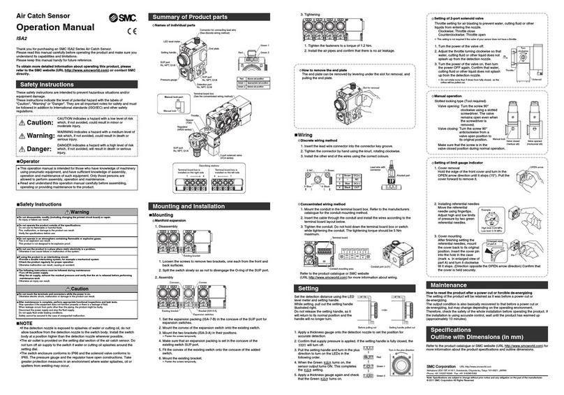
Names of individual parts
LED level meter
Setting handle
Connector for connecting lead wire
(See discrete wiring method)
Pressure gauge
SUP port
Rc, NPT, G1/8
Detection port
Rc, NPT, G1/8
SUP port
Rc, NPT, G1/8
End plate
03
Red
Green 1
Green 2
Terminal board box (See the concentrated wiring method)
Regulator (AR20 series)
Spacer (Y200-A)
Throttle
2 port solenoid valve (VCA series)
SUP port
Rc, NPT, G1/4
411 4
Describing stations
Terminal board box is
installed on the right side
Terminal board box is
installed on the left side
Red
Green 1
Above set position
Appropriate set position
Green 2 Below set position
1. Insert the lead wire connector into the connector key groove.
2. Tighten the connector by hand using the knurl, rotating clockwise.
3. Install the other end of the wires using the correct colours.
1. Mount the conduit in the terminal board box. Refer to the manufacturers
catalogue for the conduit mounting method.
2. Insert the cable through the conduit and install the wires according to the
terminal board layout below.
3. Tighten the conduit. Do not hold down the terminal board box or switch
while tightening the conduit. The tightening torque should be 5 Nm
maximum.
Concentrated wiring met od
Setting
Set the detection distance using the LED
level meter and setting handle.
While setting, pull out the setting handle
illustrated right.
Do not release the setting handle, as it
will return to its normal position and the
handle will no longer turn.
Before pulling out Setting handle pulled out
1. Apply a thickness gauge onto the detection nozzle to set the position for
accurate detection.
2. Confirm that supply pressure is applied. If the setting handle is fully closed, the
will turn off.
3. ull the setting handle and turn in the plus
direction to turn on the LEDs in the
following order.
4. When the Green turns on, the
sensor output turns ON. This completes
the setting.
5. Apply a thickness gauge again and check
that the Green turns on.
Setting of 2-port solenoid valve
Throttle setting for air blasting to prevent water, cutting fluid or other
liquids from entering the nozzle.
Clockwise: Throttle close
Counterclockwise: Throttle open
∗: This setting is not required if the valve of your sensor does not have a throttle.
1. Turn the power of the valve off.
2. Adjust the throttle turning clockwise so that
water, cutting fluid or other liquid does not
splash up from the detection nozzle.
3. Turn the power of the valve on, then turn
the power OFF again. Confirm that water,
cutting fluid or other liquid does not splash
up from the detection nozzle.
∗: Do not rotate more than 5 times from fully closed, as the
orifice will be pulled out.
Throttle
Solenoid
Turn
clockwise
IN
Manual operation
Slotted locking type (Tool required)
Valve opening: Turn the screw 90°
clockwise using a slotted
screwdriver. The valve
remains open even when
the screwdriver is
removed.
Valve closing: Turn the screw 90°
anticlockwise from a
valve open position to
its original position.
Make sure that the screw is in the
valve closed position during normal operation.
Setting of limit gauge indicator
1. Cover removal
Hold the edge of the front cover and turn in the
O EN arrow direction until it stops (15°). ull the
cover forward to remove it.
2. Installing referential needles
Move the referential
needle using fingertips.
Adjust high and low limits
of pressure by two green
referential needles.
3. Cover mounting
After finishing setting the
referential needles, mount
the cover back to its original
position. Insert the cover pin
into the hole in the case
(mark in enlarged view of
part A) and turn it clockwise
till it stops. (Direction opposite the O EN arrow direction) Confirm that
the cover is held securely.
NOTE
•If the detection nozzle is exposed to splashes of water or cutting oil, do not
allow backflow from the detection nozzle to the switch body. Install the switch
body at a position higher than the detection nozzle wherever possible.
•The air outlet is provided on the setting dial section of the air catch sensor. Do
not turn off air supply to the switch if water or cutting oil splashes around the
setting dial.
•The switch enclosure conforms to I 66 and the solenoid valve conforms to
I 65. The pressure gauge and the regulator have open constructions. Take
greater protection measures in an environment where water splashes, oil or
spatters from welding may occur.
Air Catc Sensor
Operation Manual
ISA2
Thank you for purchasing an SMC ISA2 Series Air Catch Sensor.
lease read this manual carefully before operating the product and make sure you
understand its capabilities and limitations.
lease keep this manual handy for future reference.
To obtain more detailed information about operating t is product, please
refer to t e SMC website (URL ttp://www.smcworld.com) or contact SMC
directly.
Safety Instructions
These safety instructions are intended to prevent hazardous situations and/or
equipment damage.
These instructions indicate the level of potential hazard with the labels of
"Caution", "Warning" or "Danger". They are all important notes for safety and must
be followed in addition to International standards (ISO/IEC) and other safety
regulations.
CAUTION indicates a hazard with a low level of risk
which, if not avoided, could result in minor or
moderate injury.
Operator
This operation manual is intended for those who have knowledge of machinery
using pneumatic equipment, and have sufficient knowledge of assembly,
operation and maintenance of such equipment. Only those persons are
allowed to perform assembly, operation and maintenance.
Read and understand this operation manual carefully before assembling,
operating or providing maintenance to the product.
Caution:
Warning:
Danger:
WARNING indicates a hazard with a medium level of
risk which, if not avoided, could result in death or
serious injury.
DANGER indicates a hazard with a high level of risk
which, if not avoided, will result in death or serious
injury.
Safety Instructions
Do not disassemble, modify (including c anging t e printed circuit board) or repair.
An injury or failure can result.
Do not operate in an atmosp ere containing flammable or explosive gases.
Fire or an explosion can result.
This product is not designed to be explosion proof.
Do not use t e product in a place w ere static electricity is a problem.
Otherwise it can cause failure or malfunction of the system.
If using t e product in an interlocking circuit:
•Provide a double interlocking system, for example a mec anical system
•C eck t e product regularly for proper operation
Otherwise malfunction can result, causing an accident.
T e following instructions must be followed during maintenance:
•Turn off t e power supply
•Stop t e air supply, ex aust t e residual pressure and verify t at t e air is released before performing
maintenance work
Otherwise an injury can result.
After maintenance is complete, perform appropriate functional inspections and leak tests.
Stop operation if the equipment does not function properly or there is a leakage of fluid.
When leakage occurs from parts other than the piping, the product might be faulty.
Disconnect the power supply and stop the fluid supply.
Do not apply fluid under leaking conditions.
Safety cannot be assured in the case of unexpected malfunction.
Do not touc t e terminals and connectors w ile t e power is on.
Otherwise electric shock, malfunction or damage to the product can result.
Do not operate t e product outside of t e specifications.
Do not use for flammable or harmful fluids.
Fire, malfunction, or damage to the product can result.
Verify the specifications before use.
Warning
Caution
Summary of Product parts
Mounting and Installation
1: Brown
2: NC
4: Black
3: Blue
Knurled part
Lead wire with
connector
OUT
1
OUT
2
OUT
3
OUT
4
OUT
5
OUT
6
DC
(
-
)NC
DC
(+)
Terminal board
Conduit mounting area
39
3
69
0
0
0.1 0.3
0.4
0.2
Conduit port ( 21)
1
2
DC(+)
NC
3DC(
-
)
Brown
-
Blue
4OUT
Black
Valve closed
(Vertical slit)
Valve opened
(Horizontal slit)
Manual lock
Maintenance
Refer to the product catalogue or SMC website
(URL http://www.smcworld.com) for more information about wiring.
OPEN arrow
0
0.1
0.2
0.3
0.4
High limit: 0.24 MPa
Low limit: 0.16 MPa
Example
A
Pin
Enlarged view
of part A
Red
Green 1
Green 2
Turn in the plus direction
30
69
Bracket (ISA-3-A)Existing bracket
Expansion switches
Convex
Concave
1. Set the expansion packing (ISA-7-B) in the concave of the SU port for
expansion switches.
2. Mount the convex of the expansion switch onto the existing switch.
3. Mount the two brackets (ISA-3-A) in their positions.
∗: Fasten the screws temporarily.
4. Make sure that an expansion packing is set in the concave of the
existing switch SU port.
5. Fit the convex of the existing switch onto the concave of the added
switch.
6. Mount the existing bracket.
∗: Fasten the screws temporarily.
2. Assembly
1. Tighten the fasteners to a torque of 1.2 Nm.
2. Install the air pipes and confirm that there is no air leakage.
3. Tightening
1. Disassembly
Existing bracket
1. Loosen the screws to remove two brackets, one each from the front and
back surfaces.
2. Split the switch slowly so as not to disengage the O-ring of the SU port.
How to remove t e end plate
The end plate can be removed by levering under the slot for removal, and
pulling the end plate.
Slot for removal
Mounting
Manifold expansion
Note: Specifications are subject to change without prior notice and any obligation on the part of the manufacturer.
© 2011-2015 SMC Corporation All Rights Reserved
Akihabara UDX 15F, 4-14-1, Sotokanda, Chiyoda-ku, Tokyo 101-0021, JAPAN
Phone: +81 3-5207-8249 Fax: +81 3-5298-5362
URL http://www.smcworld.com
How to reset t e product after a power cut or forcible de-energizing
The setting of the product will be retained as it was before a power cut or
de-energizing.
The output condition is also basically recovered to that before a power cut or
de-energizing, but may change depending on the operating environment.
Therefore, check the safety of the whole installation before operating the product. If
the installation is using accurate control, wait until the product has warmed up
(approximately 10 minutes).
Specifications
Outline wit Dimensions (in mm)
Refer to the product catalogue or SMC website (URL http://www.smcworld.com) for
more information about the product specifications and outline dimensions.
S※※-OMN0005-E
Manual lock
Manual lock part

Other SMC Networks Accessories manuals

SMC Networks PSE510 Series User manual

SMC Networks

SMC Networks PSE510 Series User manual

SMC Networks PSE530 Series Instruction Manual

SMC Networks

SMC Networks PSE530 Series Instruction Manual

SMC Networks PSE550 User manual

SMC Networks

SMC Networks PSE550 User manual

SMC Networks PSE540 Series Manual

SMC Networks

SMC Networks PSE540 Series Manual

SMC Networks XT477 User manual

SMC Networks

SMC Networks XT477 User manual

SMC Networks PSE57 Series User manual

SMC Networks

SMC Networks PSE57 Series User manual

SMC Networks PSE200 Series User manual

SMC Networks

SMC Networks PSE200 Series User manual

SMC Networks IZD10-*10 Series User manual

SMC Networks

SMC Networks IZD10-*10 Series User manual

SMC Networks XT477-4-X2 User manual

SMC Networks

SMC Networks XT477-4-X2 User manual

SMC Networks HRG001-W User manual

SMC Networks

SMC Networks HRG001-W User manual

SMC Networks SMC-520 User manual

SMC Networks

SMC Networks SMC-520 User manual

SMC Networks PSE550 User manual

SMC Networks

SMC Networks PSE550 User manual

SMC Networks PFM5 Series User manual

SMC Networks

SMC Networks PFM5 Series User manual

SMC Networks ADVANCE TECH HX User manual

SMC Networks

SMC Networks ADVANCE TECH HX User manual

SMC Networks PSE575 Instruction Manual

SMC Networks

SMC Networks PSE575 Instruction Manual

SMC Networks PFMV505 User manual

SMC Networks

SMC Networks PFMV505 User manual

SMC Networks PFMV5 Series User manual

SMC Networks

SMC Networks PFMV5 Series User manual

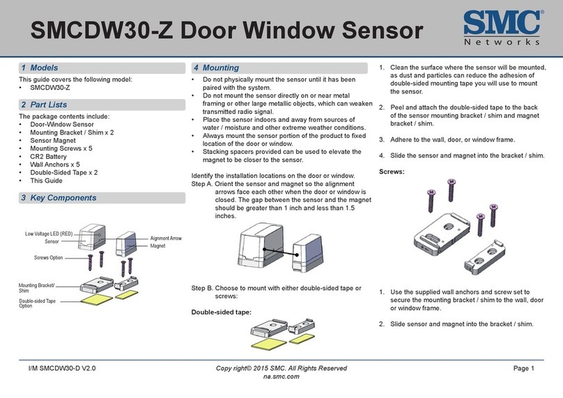
SMC Networks SMCDW30-Z User manual

SMC Networks

SMC Networks SMCDW30-Z User manual

SMC Networks PFM5 Series Instruction Manual

SMC Networks

SMC Networks PFM5 Series Instruction Manual

SMC Networks PSE575 User manual

SMC Networks

SMC Networks PSE575 User manual

SMC Networks D-MP Series User manual

SMC Networks

SMC Networks D-MP Series User manual

SMC Networks HRGC001-A Series User manual

SMC Networks

SMC Networks HRGC001-A Series User manual

SMC Networks D-MP Series User manual

SMC Networks

SMC Networks D-MP Series User manual

SMC Networks PFMV5 Series User manual

SMC Networks

SMC Networks PFMV5 Series User manual

Popular Accessories manuals by other brands

Grixx GROEXTBP50W01 user guide

Grixx

Grixx GROEXTBP50W01 user guide

Chacon 84163 quick start guide

Chacon

Chacon 84163 quick start guide

GEM 4232 operating instructions

GEM

GEM 4232 operating instructions

KROHNE OPTIFLUX 6000 quick start

KROHNE

KROHNE OPTIFLUX 6000 quick start

Ijinus LNU06V3 installation guide

Ijinus

Ijinus LNU06V3 installation guide

Pasport AirLink SI instruction sheet

Pasport

Pasport AirLink SI instruction sheet

iMSENS iMS M4-3 360 Instructions for use

iMSENS

iMSENS iMS M4-3 360 Instructions for use

Covidien Nellcor D-YS Instructions for use

Covidien

Covidien Nellcor D-YS Instructions for use

A-oneTech Air Halo Sanctuary AHS01 user manual

A-oneTech

A-oneTech Air Halo Sanctuary AHS01 user manual

PXM PX300 user manual

PXM

PXM PX300 user manual

General Monitors S214 instruction manual

General Monitors

General Monitors S214 instruction manual

Doran Scales 2200 Series Technical manual

Doran Scales

Doran Scales 2200 Series Technical manual

GOLDENSEA UV UVL150 quick start guide

GOLDENSEA UV

GOLDENSEA UV UVL150 quick start guide

Philips CRP155 brochure

Philips

Philips CRP155 brochure

Western Co Leonardo Off-Grid 8kW-8000-48 MG user manual

Western Co

Western Co Leonardo Off-Grid 8kW-8000-48 MG user manual

Kasanova MAS026823 instruction manual

Kasanova

Kasanova MAS026823 instruction manual

ETEKCITY Voltson ESO15-TB user manual

ETEKCITY

ETEKCITY Voltson ESO15-TB user manual

Life Giving Warmth The Cozee user manual

Life Giving Warmth

Life Giving Warmth The Cozee user manual

manuals.online logo
manuals.online logoBrands
  • About & Mission
  • Contact us
  • Privacy Policy
  • Terms and Conditions

Copyright 2025 Manuals.Online. All Rights Reserved.