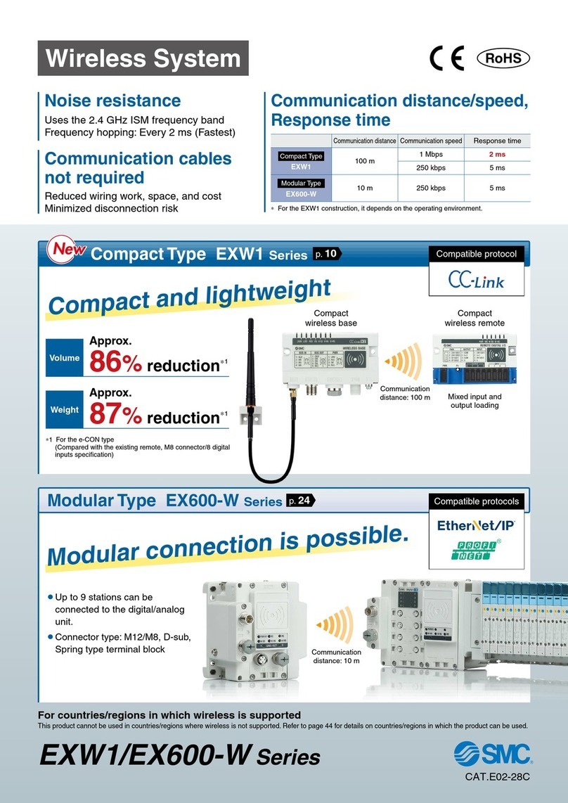
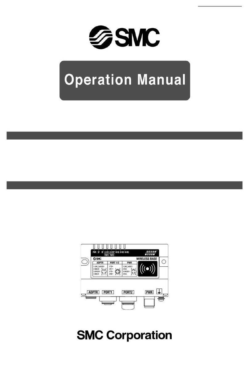
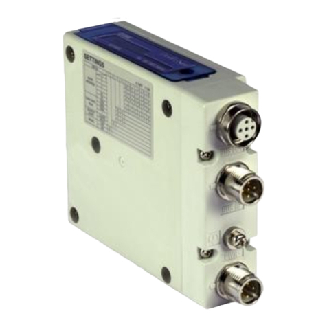
SMC Networks EXW1/EX600-W User manual

No.EX※※-OMW0006-E
PRODUCT NAME
SMC Wireless System
PROFINET compatible
MODEL / Series / Product Number
EX600-WPN# (Base)
EX600-WSV# (Remote)

-1-
No.EX※※-OMW0006-E
Contents
Safety Instructions 2
SMC Wireless System Features 10
SMC Wireless System Outline 11
Outline 11
System configuration 12
Base 13
Remote 14
Definition and terminology 15
Assembly 17
Mounting and Installation 20
Installation 20
Model Indication and How to Order 23
Summary of Product Parts 24
Connector (Base only) 25
LED Display 26
LED indication of base 26
LED indication of remote 28
Setting and Adjustment 29
Setting 30
Dimensions 44
Hardware Configuration 46
GSDML file and icon 46
Configuration Layout 46
Connection of SIEMENS PLC S7 47
I/O Map 55
I/O mapping order of base/remote 56
Diagnostic allocation 65
Detailed diagnostic data 66
Specifications 75
Troubleshooting 81
End Plate
Model Indication and How to Order 97
Summary of Product parts 98
Mounting and Installation 100
Wiring 100
Specifications 102
Dimensions 103
Accessories 113

-2-
No.EX※※-OMW0006-E
Safety Instructions
These safety instructions are intended to prevent hazardous situations and/or equipment damage.
These instructions indicatethe level of potential hazard with the labels of "Caution", "Warning" or "Danger".
They are all important notes for safety and must be followed in addition to International Standards
(ISO/IEC)*1), and other safety regulations.
*1) ISO 4414: Pneumatic fluid power -- General rules relating to systems.
ISO 4413: Hydraulic fluid power -- General rules relating to systems.
IEC 60204-1: Safety of machinery -- Electrical equipment of machines .(Part 1: General requirements)
ISO 10218: Manipulating industrial robots -Safety.
etc.
Caution
Caution indicates a hazard with a low level of risk which, if not avoided, could
result in minor or moderate injury.
Warning
Warning indicates a hazard with a medium level of risk which, if not avoided,
could result in death or serious injury.
Danger
Danger indicates a hazard with a high level of risk which, if not avoided, will
result in death or serious injury.
Warning
1. The compatibility of the product is the responsibility of the person who designs the
equipment or decides its specifications.
Since the product specified here is used under various operating conditions, its compatibility with
specific equipment must be decided by the person who designs the equipment or decides its
specifications based on necessary analysis and test results.
The expected performance and safety assurance of the equipment will be the responsibility of the
person who has determined its compatibility with the product.
This person should also continuously review all specifications of the product referring to its latest catalog
information, with a view to giving due consideration to any possibility of equipment failure when
configuring the equipment.
2. Only personnel with appropriate training should operate machinery and equipment.
The product specified here may become unsafe if handled incorrectly.
The assembly, operation and maintenance of machines or equipment including our products must be
performed by an operator who is appropriately trained and experienced.
3. Do not service or attempt to remove product and machinery/equipment until safety is
confirmed.
1. The inspection and maintenance of machinery/equipment should only be performed after measures to
prevent falling or runaway of the driven objects have been confirmed.
2. When the product is to be removed, confirm that the safety measures as mentioned above are
implemented and the power from any appropriate source is cut, and read and understand the specific
product precautions of all relevant products carefully.
3. Before machinery/equipment is restarted,take measures to prevent unexpected operation and malfunction.
4. Contact SMC beforehand and take special consideration of safety measures if the
product is to be used in any of the following conditions.
1. Conditions and environments outside of the given specifications, or use outdoors or in a place
exposed to direct sunlight.
2. Installation on equipment in conjunction with atomic energy, railways, air navigation, space, shipping,
vehicles, military, medical treatment, combustion and recreation, or equipment in contact with food and
beverages, emergency stop circuits, clutch and brake circuits in press applications, safety equipment or
other applications unsuitable for the standard specifications described in the product catalog.
3. An application which could have negative effects on people, property, or animals requiring special
safety analysis.
4. Use in an interlock circuit, which requires the provision of double interlock for possible failure by using
a mechanical protective function, and periodical checks to confirm proper operation.

-3-
No.EX※※-OMW0006-E
Safety Instructions
Caution
1.The product is provided for use in manufacturing industries.
The product herein described is basically provided for peaceful use in manufacturing industries.
If considering using the product in other industries, consult SMC beforehand and exchange
specifications or a contract if necessary.
If anything is unclear, contact your nearest sales branch.
Limited warranty and Disclaimer/Compliance Requirements
The product used is subject to the following "Limited warranty and Disclaimer" and "Compliance
Requirements".
Read and accept them before using the product.
Limited warranty and Disclaimer
1. The warranty period of the product is 1 year in service or 1.5 years after the product is
delivered, whichever is first.2)
Also, the product may have specified durability, running distance or replacement parts.
Please consult your nearest sales branch.
2. For any failure or damage reported within the warranty period which is clearly our
responsibility, a replacement product or necessary parts will be provided.
This limited warranty applies only to our product independently, and not to any other
damage incurred due to the failure of the product.
3. Prior to using SMC products, please read and understand the warranty terms and
disclaimers noted in the specified catalog for the particular products.
2) Vacuum pads are excluded from this 1 year warranty.
A vacuum pad is a consumable part, so it is warranted for a year after it is delivered.
Also, even within the warranty period, the wear of a product due to the use of the
vacuum pad or failure due to the deterioration of rubber material are not covered by the
limited warranty.
Compliance Requirements
1. The use of SMC products with production equipment for the manufacture of weapons of
mass destruction (WMD) or any other weapon is strictly prohibited.
2. The exports of SMC products or technology from one country to another are governed by
the relevant security laws and regulation of the countries involved in the transaction. Prior
to the shipment of a SMC product to another country, assure that all local rules governing
that export are known and followed.

-4-
No.EX※※-OMW0006-E
Operator
This operation manual is intended for those who have knowledge of machinery using pneumatic
equipment, and have sufficient knowledge of assembly, operation and maintenance of such
equipment. Only those persons are allowed to perform assembly, operation and maintenance.
Read and understand this operation manual carefully before assembling, operating or providing
maintenance to the product.
■Safety Instructions
Warning
■Do not disassemble, modify (including changing the printed circuit board) or repair.
An injury or failure can result.
■Do not operate or set with wet hands.
This may lead to an electric shock.
■Do not operate the product outside of the specifications.
Do not use for flammable or harmful fluids.
Fire, malfunction, or damage to the product can result.
Verify the specifications before use.
■Do not operate in an atmosphere containing flammable or explosive gases.
Fire or an explosion can result.
This product is not designed to be explosion proof.
■If using the product in an interlocking circuit:
•Provide a double interlocking system, for example a mechanical system.
•Check the product regularly for proper operation.
Otherwise malfunction can result, causing an accident.
■The following instructions must be followed during maintenance:
•Turn off the power supply.
•Stop the air supply, exhaust the residual pressure and verify that the air is released before performing
maintenance.
Otherwise an injury can result.

-5-
No.EX※※-OMW0006-E
Caution
■When handling the unit or assembling/replacing units:
•Do not touch the sharp metal parts of the connector or plug for connecting units.
•Take care not to hit your hand when disassembling the unit.
The connecting portions of the unit are firmly joined with seals.
•When joining units, take care not to get fingers caught between units.
An injury can result.
■After maintenance is complete, perform appropriate functional inspections.
Stop operation if the equipment does not function properly.
Safety cannot be assured in the case of unexpected malfunction.
■Provide grounding to assure noise resistance of the Fieldbus system.
Individual grounding should be provided close to the product with a short cable.
Caution
Notice:
Changes or modifications not expressly approved by the manufacturer could void the user's authority to operate the
equipment.
NOTE:
This equipment has been tested and found to comply with the limits for a Class A digital device, pursuant to Part 15
of the FCC Rules.
These limits are designed to provide reasonable protection against harmful interference when the equipment is
operated in a commercial environment.
This equipment generates, uses, and can radiate radio frequency energy and, if not installed and used in accordance
with the instruction manual, may cause harmful interference to radio communications.
Operation of this equipment in a residential area is likely to cause harmful interference in which case the user will be
required to correct the interference at his own expense.

-6-
No.EX※※-OMW0006-E
This device complies with Industry Canada’s licence-exempt RSSs. Operation is subject to the following two
conditions:
(1) This device may not cause interference; and
(2) This device must accept any interference, including interference that may cause undesired operation of
the device.
Le présent appareil est conforme aux CNR d'Industrie Canada applicables aux appareils radio exempts de
licence. L'exploitation est autorisée aux deux conditions suivantes:
(1) l'appareil ne doit pas produire de brouillage, et
(2) l'utilisateur de l'appareil doit accepter tout brouillage radioélectrique subi, même si le brouillage est
susceptible d'en compromettre le fonctionnement.
Caution
When operating the product, please be sure to maintain a separation distance of at least 20 cm between your
body (excluding fingers, hands, wrists, ankles and feet) and the product to meet RF exposure safety
requirements as determined by FCC and Innovation, Science and Economic Development Canada.
Installation of this device must ensure that at 20 cm separation distance is maintained between the device
and end users.
警語
經型式認證合格之低功率射頻電機,非經許可,公司,商號或使用者均不得擅自變更頻率,加大功率或變更原
設計之特性及功能。
低功率射頻電機之使用不得影響飛航安全及干擾合法通信;經發現有干擾現象時,應立即停用,並改善至無干
擾時方得繼續使用。
前項合法通信,指依電信法規定作業之無線電通信。低功率射頻電機須忍受合法通信或工業,科學及醫療用電
波輻射性電機設備之干擾。

-7-
No.EX※※-OMW0006-E
■NOTE
○Follow the instructions given below when designing, selecting and handling the product.
●The instructions on design and selection (installation, wiring, environment, adjustment,
operation, maintenance, etc.) described below must also be followed.
Product specifications
•Use the specified voltage.
Otherwise failure or malfunction can result.
•Reserve a space for maintenance.
Allow sufficient space for maintenance when designing the system.
•Do not remove any nameplates or labels.
This can lead to incorrect maintenance, or misreading of the operation manual, which could cause damage or
malfunction to the product.
It may also result in non-conformity to safety standards.
•Beware of inrush current when the power supply is turned on.
Some connected loads can apply an initial charge current which will activate the over current protection function,
causing the unit to malfunction.

-8-
No.EX※※-OMW0006-E
●Product handling
Installation
•Do not drop, hit or apply excessive shock to the SI unit.
Otherwise damage to the product can result, causing malfunction.
•Tighten to the specified tightening torque.
If the tightening torque is exceeded the mounting screws may be broken.
IP67 protection cannot be guaranteed if the screws are not tightened to the specified torque.
•If a large manifold valve is mounted, lift the unit so that stress is not applied to the connecting part while
transporting.
The stress may cause breakage of the connecting part. The unit may become very heavy depending on the
combination. Transportation/installation shall be performed by multiple operators.
•Never mount a product in a location that will be used as a foothold.
The product may be damaged if excessive force is applied by stepping or climbing onto it.
Wiring
•Avoid repeatedly bending or stretching the cables, or placing heavy load on them.
Repetitive bending stress or tensile stress can cause breakage of the cable.
•Wire correctly.
Incorrect wiring can break the product.
•Do not perform wiring while the power is on.
Otherwise damage to the wireless unit and/or input or output device can result, causing malfunction.
•Do not route wires and cables together with power or high voltage cables.
Otherwise the wireless unit and/or input or output device can malfunction due to interference of noise and surge
voltage from power and high voltage cables to the signal line.
Route the wires (piping) of the wireless unit and/or input or output device separately from power or high voltage
cables.
•Confirm proper insulation of wiring.
Poor insulation (interference from another circuit, poor insulation between terminals, etc.) can lead to excess
voltage or current being applied to the product, causing damage.
•Take appropriate measures against noise, such as using a noise filter, when the Fieldbus system is
incorporated into equipment.
Otherwise noise can cause malfunction.
Environment
•Select the proper type of protection according to the environment of operation.
IP67 protection class is achieved when the following conditions are met.
(1) The units are connected properly with fieldbus cable with M12 connector and power cable with M12 (M8)
connector.
(2) Suitable mounting of each unit and manifold valve.
(3) Be sure to fit a waterproof cap on any unused connectors.
If using in an environment that is exposed to water splashes, please take measures such as using a cover.
Do not use in an environment where moisture or water vapor are present. Otherwise failure and malfunction can
result.
•Do not use in a place where the product could be splashed by oil or chemicals.
If the product is to be used in an environment containing oils or chemicals such as coolant or cleaning solvent, even
for a short time, it may be adversely affected (damage, malfunction etc.).
•Do not use the product in an environment where corrosive gases or fluids could be splashed.
Otherwise damage to the product and malfunction can result.
•Do not use in an area where surges are generated.
If there is equipment generating large surge near the unit (magnetic type lifter, high frequency inductive furnace,
welding machine, motor, etc.), this can cause deterioration of the internal circuitry element of the unit or result in
damage. Take measures against the surge sources, and prevent the lines from coming into close contact.
-9-
No.EX※※-OMW0006-E
•When a surge-generating load such as a relay, valve or lamp is driven directly, use a product with a
built-in surge absorbing element.
Direct drive of a load generating surge voltage can damage the unit.
•The product is CE/UKCA marked, but not immune to lightning strikes. Take measures against lightning
strikes in the system.
•Prevent foreign matter such as dust or wire debris from getting inside the product.
•Mount the product in a place that is not exposed to vibration or impact.
Otherwise failure or malfunction can result.
•Do not use the product in an environment that is exposed to temperature cycle.
Heat cycles other than ordinary changes in temperature can adversely affect the inside of the product.
•Do not expose the product to direct sunlight.
If using in a location directly exposed to sunlight, shade the product from the sunlight.
Otherwise failure or malfunction can result.
•Keep within the specified ambient temperature range.
Otherwise malfunction can result.
•Do not operate close to a heat source, or in a location exposed to radiant heat.
Otherwise malfunction can result.
Adjustment and Operation
•Please refer to the I/O configuration manual for details of parameter settings.
•Perform settings suitable for the operating conditions.
Incorrect setting can cause operation failure.
(Refer to page 29 for the Setting andAdjustment.)
•Please refer to the PLC manufacturer's manual etc. for details of programming and addresses.
For the PLC protocol and programming refer to the relevant manufacturer's documentation.
Maintenance
•Turn off the power supply, stop the supplied air, exhaust the residual pressure and verify the release of
air before performing maintenance.
There is a risk of unexpected malfunction.
•Perform regular maintenance and inspections.
There is a risk of unexpected malfunction.
•After maintenance is complete, perform appropriate functional inspections.
Stop operation if the equipment does not function properly.
Otherwise safety is not assured due to an unexpected malfunction or incorrect operation.
•Do not use solvents such as benzene, thinner etc. to clean each unit.
They could damage the surface of the body and erase the markings on the body.
Use a soft cloth to remove stains.
For heavy stains, use a cloth soaked with diluted neutral detergent and fully squeezed, then wipe up the stains
again with a dry cloth.

-10-
No.EX※※-OMW0006-E
SMC Wireless System Features
The SMC wireless system has the following features:
•High-speed start up. The minimum connection time to the system after supplying power to the remote is 0.25
seconds.1
•Parameter setting by Near Field Communication (NFC) using a PC (no HW setting).
•Up to 31 remote can be registered to one base.2
•The maximum number of I/O points of the wireless system is 1280 for input and output. 3, 4
•The maximum number of I/O points of the base is 128 for input and output.
•The maximum number of I/O points of the remote is 128 for input and output.
1: The base should be in the start upstate. The connection time varies depending on the timing of the power supply to the remote, the
number of connected EX600 I/O units and other external influences.
2: The maximum number of units that can be connected is 31. If 31 units is exceeded, the unit I/O will not be recognized.
There might be a communication delay depending on the communication load status.
3: The maximum number of I/O point is 1280 for input and output. When exceeding 1280 points, the unit I/O is not recognized.
There might be a communication delay depending on the communication load status.
4: The total number of I/O points of the base and the registered I/O points of the remote.
<Important >
●This product is a wireless unit in accordance with the Radio Act.
Be sure to comply with the following precautions.
•Do not disassemble or modify the product. Disassembly and modification are prohibited by law.
•This product is compliant with the Radio Act in Japan, European countries and the US. Refer to the product
catalog or SMC website (URL https://www.smcworld.com) for the latest information.
: If this product is to be imported into Malaysia (including if the product is integrated into other equipment), an SMC Wireless System
Certificate of Compliance and a test report may be required in some cases. Please contact SMC for further details.
●This product communicates by radio waves, and the communication may stop instantaneously due to
ambient environments and operating methods. SMC will not be responsible for any secondary failure which
may cause an accident or damage to other devices or equipment.
●When several units are installed closely to each other, slight interference may occur due to the
characteristics of the wireless product.
●The electromagnetic waves emitted from this product may interfere with implantable medical devices such
as cardiac pacemakers and cardioverter defibrillators, resulting in the malfunction of the medical device or
other adverse effects.
Please use extreme caution when operating equipment which may have an adverse effect on your
implantable medical device. Be sure to thoroughly read the precautions stated in the catalog, operation
manual, etc., of your implantable medical device, or contact the manufacturer directly for further details on
what types of equipment need to be avoided.
●The communication performance is affected by the ambient environment, so please perform the
communication testing before use.

-11-
No.EX※※-OMW0006-E
SMC Wireless System Outline
■Outline
This operation manual describes the distributed I/O system which can provide a wireless connection to
the EX600 series with complete interchangeability.
It consists of a combination of the base which has upper level communication (PROFINET) and wireless
connection function and the remote which offers wireless connection.
The base and remote can be constructed into modules by combining them with EX600 series I/O units.
Each base and remote is able to provide up to 128 inputs and 128 outputs, and up to 9 I/O units can be
connected to each module.
Although the base is able to provide up to 128 inputs and 128 outputs as a base, it is possible to have up to
1280 inputs and 1280 outputs by matching the number of I/O points of the registered remote.
Therefore, the maximum number of I/O points per 1 node can be 1280 points (160 bytes)/1280 points (160
bytes) visible from the upper level communication such as a PLC.
It is possible to prevent malfunction when multiple base and remote are being operated in the same area by
registering each PID (Product ID) of the base and the remote.
The packet of the wireless transmit and receive data is encrypted. It is therefore difficult to manipulate the
data.

-12-
No.EX※※-OMW0006-E
■System configuration
Wireless system configuration example

-13-
No.EX※※-OMW0006-E
■Base
The construction of the base is shown below.
Base construction example
The base is positioned at the center of the base, so that the EX600 I/O units can be connected to
the left side of the base and the valve manifold can be connected to the right side of the base.
Refer to the SMC catalogue for the EX600 series serial transmission system for the wiring method.
http://ca01.smcworld.com/catalog/BEST-5-1-en/mpv/e02-24-ex600/pageview.html#page_num=C1
The base transmits and receives the I/O unit information from the base and remote when connected to the
upper level communication PROFINET system.
With the wireless system the allocation direction of the address (Slot No.) setting allocated to the EX600
I/O unit and the connected valve manifold can be varied for each wireless unit.
(Refer to page 35 the section "Setting and Adjustment" for details.)

-14-
No.EX※※-OMW0006-E
■Remote
The construction of the remote is shown below.
Remote construction example
The remote is positioned at the center of the remote, so that the EX600 I/O units can be connected to
the left side of the remote and the valve manifold can be connected to the right side of the remote, similar
to the base.
Refer to the SMC catalogue for the EX600 series serial transmission system for the wiring method.
http://ca01.smcworld.com/catalog/BEST-5-1-en/mpv/e02-24-ex600/pageview.html#page_num=C1
The remote has a construction that is separated from the PROFINET communication function by the base,
and therefore it transmits/receives the information of the connected I/O units and valve manifold to/from the
base.
With the wireless system the allocation direction of the address (Slot No.) setting allocated to the EX600
I/O unit and the connected valve manifold can be varied for each wireless unit.
(Refer to page 40 the section "Setting and Adjustment" for details.)

-15-
No.EX※※-OMW0006-E
■Definition and terminology
Term
Definition
100
100BASE-TX
Standard LAN transmission line with communication speed of 100 Mbps.
B
Base
A unit which establishes wireless communication of input or output data to the remote. It is
connected to a PLC to establish communication of input or output data.
Broken line
detection
A broken wire to the input or output equipment has been detected by the diagnostic
function.
C
Current
consumption
Current which is necessary to operate each unit.
D
DHCP
A protocol that automatically allocates information, necessary to be registered to use the
network, such as an IP address, to individual devices connected to the TCP/IP network.
DIN rail
A metal rail conforming with the DIN (German) standard.
D Side
The side connected to the end plate when the product is connected to a manifold.
E
Enclosure (IP)
Abbreviation of International Protection. Standard related to protection against extraneous
matter, such as hand, steel ball, steel wire, dust particle or water, applied to the product.
F
FE
Abbreviation of functional earth. The word "earth" refers to this functional earth.
Fieldbus
Network protocol to establish digital communication between an automated industrial
system such as a measurement tool or manipulation tool and a PLC.
Full duplex
Communication system that can send and receive data at the same time bi-directionally.
FSU
Stands for Fast Start Up. Function to shorten the time from initial operation of the equipment
after supplying power to starting communication.
G
GSDML file
File describes the product base data.
H
Half-duplex
Communication method that can send and receive data reciprocally in bi-directional
communication.
I
Idle
Base has received the FAIL SAFE command, and remains idle. The output state can be set
to CLEAR, HOLD or Software Control using the parameter settings.
IP address
A 32 bit digit sequence which is assigned to identify devices which are connected to the
network.
M
MAC address
A unique number inherent to all devices connected to an PROFINET network.
Manifold
Aggregate.
MRP
Stands for Media Redundancy Protocol. Performs fast switching to a redundant
communication route, when a problem occurs within a Ring network.
N
NFC
Abbreviation of Near Field Communication. Non-contact short distance wireless
communication. It is accessible using a card reader/writer by using a special application.
NPN output
The output type that uses an NPN transistor to operate an output device. This is also known
as a positive common type since a positive potential is applied to the power supply line.
NPN input
Accepts a sensor output that uses the NPN transistor output signal.
Number of inputs
Number of points which can receive information from input equipment such as a sensor or
switch.
Number of
outputs
Number of points which can operate output equipment such as a valve, lamp or motor
starter.

-16-
No.EX※※-OMW0006-E
Term
Definition
P
Paring
Registration of the PID (Product ID) of the remote to be connected to the base. Registration
occurs at the initial setting, then wireless system will activate.
PID
Abbreviation of Product ID. A 32 bit digit sequence which is assigned to identify the wireless
unit (base/remote).
PLC
Abbreviation of Programmable Logic Controller. A digital computer used for automation of
electromechanical processes.
PNP output
The output type that uses a PNP transistor to operate an output device. This is also known
as a negative common type since a negative potential is applied to the power supply line.
PNP input
Accepts a sensor output that uses the PNP transistor output signal.
R
Remote
A unit which establishes wireless communication of input or output data to the base.
S
Short circuit
detection
Diagnostic function which detects generation of over current due to a short circuit between
the output and the positive power supply line or the ground line.
Short circuit
protection
Function which avoids damage to the internal circuit when over current is generated due to
short circuit between the output and the positive power supply line or the ground line.
U
U side
The side connected to the valve manifold when the EX600 is connected to a manifold.
W
Wireless channel
Identification number of the remote connected to the base.
Wireless system
This is a general term for the network including base and remote.
Wireless unit
A unit which establishes wireless communication. This is a generic name of the base and
remote.

-17-
No.EX※※-OMW0006-E
Assembly
●Assembling the unit as a manifold
(1) Connect a unit to the end plate.
Digital and analogue units can be connected in any order.
(Tightening torque: 1.5 to 1.6 Nm)
(2) Add more units.
Up to 9 units can be connected to one manifold.
(3) Connecting the wireless unit
After connecting the required I/O units, connect the wireless unit.
The connection method is as above.

-18-
No.EX※※-OMW0006-E
(4) Mounting the valve plate. (Valve manifold not connected → Refer to page 19)
Mount the valve plate (EX600-ZMV#) to the valve manifold using the set screws (M3 x 8) provided with
the product. (Tightening torque: 0.6 to 0.7 Nm)
Screw mounting
places
SV: 2 places
S0700: 2 places
VQC1000: 2 places
VQC2000: 3 places
VQC4000: 4 places
SY: 2 places
(5) Connect the wireless unit to the valve manifold.
Insert the valve plate into the valve plate mounting groove on the side of the wireless unit, and then fix
both surfaces of the plate using the valve plate mounting screws (M4 x 6) provided with the product.
(Tightening torque: 0.7 to 0.8 Nm)

-19-
No.EX※※-OMW0006-E
(6) When valve manifold is not connected.
Insert the end plate (EX600-EU1) into the valve plate mounting groove on the side of the wireless unit,
and then fix both surfaces of the plate using the valve plate mounting screws (M4 x 6) provided with the
product. (Tightening torque: 0.7 to 0.8 Nm)
●Handling Precautions
•Do not connect units with power supplied.
•Be careful not to drop the nut for the joint bracket.
•Tighten the screws to the specified torque.
Insufficient tightening may lead to equipment malfunction, injury or equipment damage.
This manual suits for next models
2
Table of contents
Other SMC Networks Microphone System manuals

SMC Networks
SMC Networks EX600-WEN User manual

SMC Networks
SMC Networks EXW1-BPNAC1 User manual

SMC Networks
SMC Networks EX140-SMJ1 Series User manual

SMC Networks
SMC Networks EX600-WSV User manual

SMC Networks
SMC Networks EXW1 Series User manual

SMC Networks
SMC Networks EX600-W Series User manual

SMC Networks
SMC Networks SI Unit User manual

SMC Networks
SMC Networks EX600-ED Series User manual