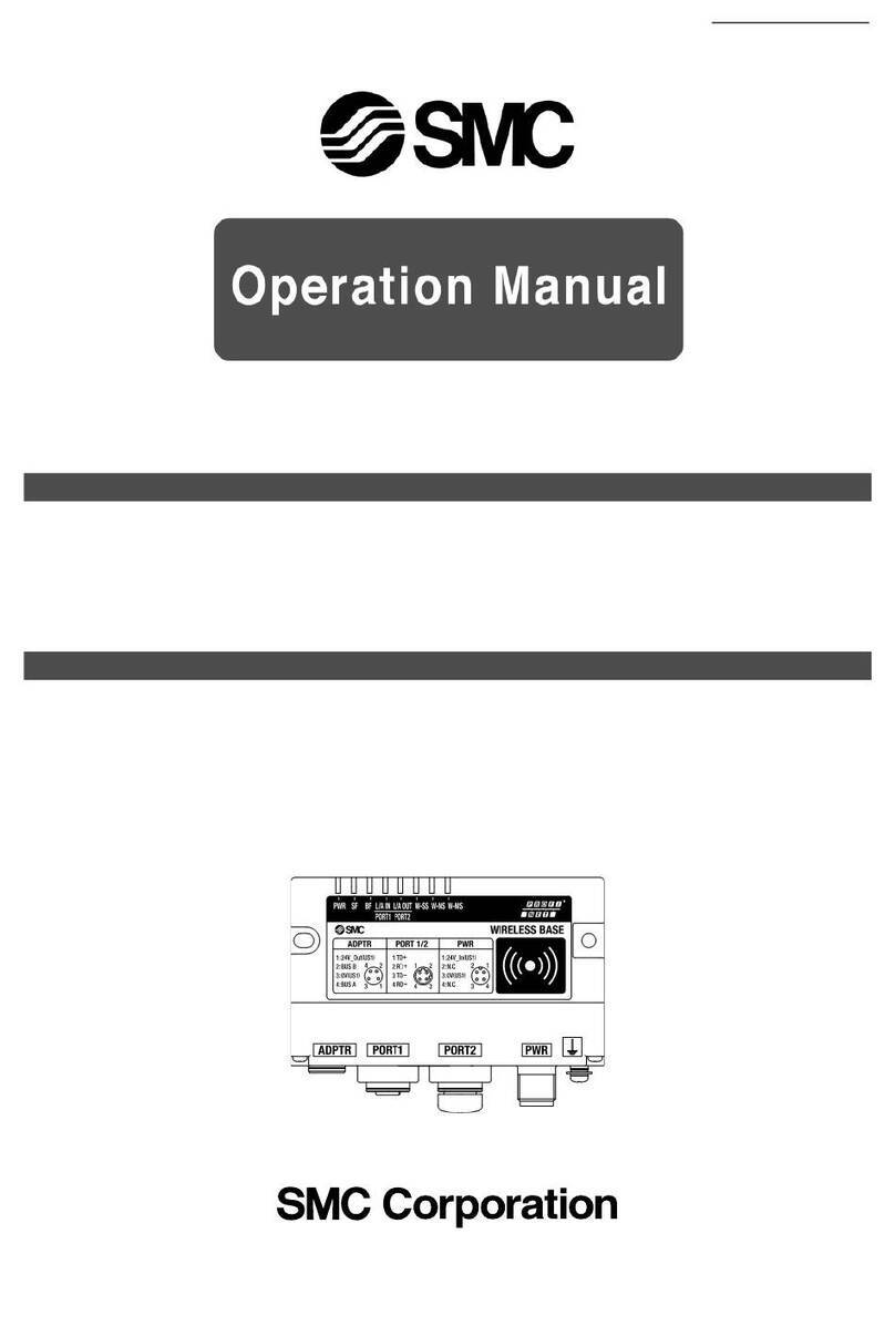
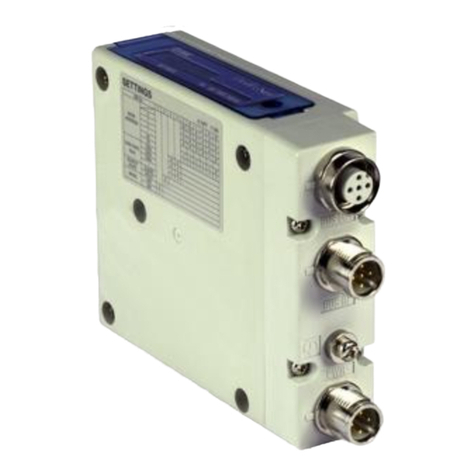
SMC Networks EXW1 Series User manual

Wireless System
Approx.
86%reduction∗1
Approx.
87%reduction∗1
Volume
Weight
Compact
wireless base
Compact
wireless remote
Mixed input and
output loading
Noise resistance
Uses the 2.4 GHz ISM frequency band
Frequency hopping: Every 2 ms (Fastest)
For countries/regions in which wireless is supported
This product cannot be used in countries/regions where wireless is not supported. Refer to page 44 for details on countries/regions in which the product can be used.
¡Up to 9 stations can be
connected to the digital/analog
unit.
¡Connector type: M12/M8, D-sub,
Spring type terminal block
Communication cables
not required
Reduced wiring work, space, and cost
Minimized disconnection risk
Communication distance
Communication speed
Response time
Compact Type
EXW1 100 m 1 Mbps 2 ms
250 kbps 5 ms
Modular Type
EX600-W 10 m 250 kbps 5 ms
∗For the EXW1 construction, it depends on the operating environment.
Communication distance/speed,
Response time
Compact Type EXW1 Series
Modular Type EX600-W Series
NewNew Compatible protocol
Compatible protocols
Compact and lightweight
Modular connection is possible.
Communication
distance: 100 m
Communication
distance: 10 m
∗1 For the e-CON type
(Compared with the existing remote, M8 connector/8 digital
inputs specification)
p. 10
p. 24
CAT.E02-28C
EXW1/EX600-W Series
RoHS

Wireless System Compact Type EXW1 Series /Modular Type EX600-W Series
Wireless base area 1
AGVs (Automatic Guided
Vehicles) are being used.
Wireless network (Existing)
Wireless base area 2
Provides communication stability in FA environments
¡Even if multiple wireless bases are in use in the same communication area, each wireless base is able to effectively
communicate with the remotes they are paired with. Each wireless base is able to identify its wireless remotes by their P.I.D.
∗ P.I.D.: Product I.D.
Supports external antennas
Communication is possible with an external antenna even when the wireless base/remote is installed
in a metal-shielded location such as in a control panel/box.
External antenna
Compact
wireless base
Wireless base
Wireless remote
Wireless base
Wireless remote
Wireless
remote
Control boxControl panel
Compact remote
Compact
EXW1
Compact
EXW1
Modular
EX600-W
Noise in
electronic
circuits
Interference
from other
wireless
equipment
Stable communication is possible.
¡ Communication is possible in environments with various forms of propagation (transmission, reflection, etc.).
¡ Communication is also possible within the same area as existing wireless networks such as wireless LANs and AGVs.
External antenna
type
1

Time
Frequency
2 ms or 5 ms
Actual communication time
Frequency of the radio wave interference
Communication frequency interference (for example, Wi-Fi)
No event (no signal output)
Event (signal output)
Output
Used by wireless LANs
1 ch to 79 ch
Used by
other wireless devices
kHz MHz GHz
Wireless System
Wireless LAN
RFID
Bluetooth
AC/DC welding
machine
Motor driver/
Electromagnetic heater, etc.
10 10 101 1100 100
Wireless System Compact Type EXW1 Series /Modular Type EX600-W Series
F.C.S. (Frequency channel select) function supported
This is a function that allows for the selection of the frequency channel to be hopped to via frequency hopping. When the
frequency used by wireless LANs, AGVs, or other wireless devices is known, selecting a different frequency channel will allow
for hopping only to the selected frequency channel, thereby reducing communication collisions with other wireless devices and
stabilizing communication.
∗The number of selectable frequency channels varies depending on the country of use.
¡Countries other than the U.S., Canada, and South Korea: 5 to 79 ch ¡U.S., Canada, and South Korea: 15 to 79 ch
∗ If no channel is selected, hopping/communication is established on 79 ch by default.
Frequency hopping
Event communication system
A stable wireless environment is established using an
original protocol which is not affected by interference.
Interference from other wireless equipment is reduced.
Wireless communication is performed only when there
is a variation in the information, thereby suppressing
the frequency of radio wave output in wireless
communication and reducing interference with other
wireless devices.
Hopping/communicating with the frequency channel within the selected red frame
Frequency hopping/Event communication system
∗1
For the EXW1 only
High security
using encryption
Unauthorized access from outside is
prevented by using data encryption.
Remote
Unauthorized access/
data falsification
Unauthorized
wiretapping
Removing
device
Frequency band used
Uses the 2.4 GHz ISM frequency band
Wireless
devices
Site
noise
∗ISM (Industrial, Scientific, and Medical) radio bands: Frequency bands allocated for
industrial, scientific, and medical applications
Remote high-speed connection
To start of communication: Min.
250
ms
∗
Depends on the communication environment
Base
Compact
EXW1
Compact
EXW1
Compact
EXW1
Compact
EXW1
Compact
EXW1
Modular
EX600-W
Modular
EX600-W
Modular
EX600-W
Modular
EX600-W
Frequency
hopping cycle
2 ms∗1
or
5 ms
2

Wireless System Compact Type EXW1 Series /Modular Type EX600-W Series
PLC
Solenoid valve
NFC reader/
writer
PC + Setting software
PC
Wireless base
Diagnostic signal
Diagnostic signal
LED display for remotes
LED display for bases
Web function
Web function
Setting software
(IO Configurator)
Wireless remote
∗only
NewNew
NewNew
Diagnostic signals , LEDs on the base/remote , Web function , and setting software (IO Configurator) can be used for
product diagnostics.
The LED display can be used to identify the
installation location and communication status
according to the received signal strength level.
The LED display can be used to identify the
installation location and communication status
according to the received signal strength level.
The connection status of the wireless
system can be judged by the PLC during
operation by the diagnostic signal.
<Diagnostic signal output conditions>
¡ When communication from the remote
cannot be received
¡ When the number of communication
retries has exceeded the upper limit
Product diagnosis
By connecting the base and PC, you can set up the product/wireless
communication and check the communication status on the web
screen. Log data of the number of wireless communication retries and
of the received signal strength can be generated from the web screen
and downloaded in a CSV file. The wireless
environment and installation location can
be optimized by checking the number of
retries and the received radio wave
intensity.
∗Refer to the logging function on page 4.
The log files showing the number
of retries or the received radio
wave intensity can be downloaded
in the form of a CSV file.
Web screen example
PC
Compact
EXW1
Modular
EX600-W
EXW1
EXW1
EX600-W
EX600-W
Compact Type
Compact Type
Modular Type
Modular Type
Fieldbus
and
W-SS (Radio wave receiving intensity
(For communication from base to remote))
Green LED is ON.
The r
eceived power level is 3.
Green LED flashes. (1 Hz)
The r
eceived power level is 2.
Green LED flashes. (2 Hz)
The r
eceived power level is 1.
Red LED flashes.
Wireless communication is not connected.
OFF
The b
ase module is not registered.
W-SS (Radio wave receiving intensity
(For communication from remote to base))
Green LED is ON.
The received power level of all remotes
is 3.
Green LED flashes. (1 Hz)
There are connected remotes with a
received power level of 2.
Green LED flashes. (2 Hz)
There are connected remotes with a
received power level of 1.
Red LED flashes. No remotes are connected.
OFF
The r
emote module is not registered.
Web screen example
3
Information I/O monitor Properties Event Wireless
ALL CLEAR Refresh
Power on
R/W detected
WCh Unit Channel Status
3 5 0x00000001
1 2 0x00000002
1 2 0x00000002
1 4 0x00000003
1 4 0x00000004
3 5 0x00000005
5
3
2
3
1
5
4 3 5 0x00000006
EX600-WSV1
EX600-WSV1
LINE4-S5-R-HAND
LINE4-S5-L-HAND
LINE4-S5-R-HAND
LINE4-S3-R-HAND
LINE4-S2-R-HAND
Export
TAG
Scroll bar
Timestamp
2020/12/28 10:26:25
2020/12/26 8:00:00
2020/12/24 5:33:35
2020/12/22 3:07:10
2020/12/20 0:40:45
2020/12/17 22:14:20
2020/12/15 19:47:55
∗
1 Characteristics of base-to-remote transmission packets
Graph 1. Communication response characteristics
7047302
751991
92769
56710000000000000000000000000000
0%
10%
20%
30%
40%
50%
60%
70%
80%
90%
100%
0 1 2 3 4 5 6 7 8 9 10 11 12 13 14 15 16 17 18 19 20 21 22 23 24 25 26 27 28 29 30 31
0
1000000
2000000
3000000
4000000
5000000
6000000
7000000
8000000
Number of base transmission attempts [times] (∗1)
Frequency of trials [Packet]
Frequency of trials Success rate of communication establishment
Success rate until communication establishment
Communication trial rate
(∗1)
∗1
Characteristics of base-to-remote transmission packets
Graph 2. Received signal strength indicator and communication trial rate characteristics with respect to frequency
0%
10%
20%
30%
40%
50%
60%
70%
80%
90%
100%
-100
-90
-80
-70
-60
-50
-40
-30
-20
-10
0
2403 2408 2413 2418 2423 2428 2433 2438 2443 2448 2453 2458 2463 2468 2473
Frequency [MHz]
Communication trial rate RSSI from base to remote
Received signal strength indicator (RSSI) [dBm]
RSSI from remote to base
Wireless System Compact Type EXW1 Series /Modular Type EX600-W Series
Logging function
The following information is saved in the internal memory of the product. It can be downloaded and visualized from the web
function or the setting software (IO Configurator).
Received signal strength indicatorNumber of retries
Operation status
Compact
EXW1
Modular
EX600-W
The number of retries (communication attempts) can be checked.
Error details, time information (timestamp), and remote numbers can be checked.
∗Up to 30 pieces can be displayed.
The communication trial rate and received signal strength indicator (RSSI)
can be checked for every frequency channel.
Number of retries, Received signal strength indicator, Operation status
PC + Setting software
NFC reader/
writer
Setting software
The NFC reader/writer can be used with the setting software
to perform various checks and setting without contact.
(NFC: Near Field Communication)
¡Base communication configuration
¡Setting of the I/O points for the system, base, and remote
¡Pairing of the base and remote
¡I/O monitoring
¡Monitoring of diagnostic data
∗Refer to the logging function.
Documents/Download
Instruction Manuals
Fieldbus System
Serial Transmission System
EtherNet/IP™ Compatible
or
PROFINET Compatible
I/O Configurator for NFC
From the SMC website
Download the setting software from
the “configuration file.”
Setting software (IO Configurator)
Configuration File
Product diagnosis Compact
EXW1
Modular
EX600-W
Configuration File
… …
4

Wireless System Compact Type EXW1 Series /Modular Type EX600-W Series
EX600 I/O unit
Base module
PLC
System Examples
Remote module
Solenoid valve
EX600 I/O unit
Refer to
the Web Catalog.
∗While limited to radio-enabled countries (Japan, the United States, Canada, and the EU), compact remote types are available for connecting IO-Link devices.
For further details, refer to the SMC website, and contact your local sales representative.
Others
Indicator light
Relay
Buzzer
Solenoid valveValve manifold
(Plug lead)
Vacuum unit
Output devices
Input/Output
device
Input devices
Fieldbus
The compact EXW1 and the modular EX600-W can be mixed.∗1
Wireless base
Wireless remote
Mixed input
and output
loading
Input Output
∗1 When they are mixed, the communication speed/response time is limited to the EX600-W’s specifications. (Refer to the system configuration examples.)
Auto switch Pressure
switch
Flow switch Others
Proximity sensor
Photoelectric switch
Limit switch
NewNew
NewNew
EXW1
EXW1
EX600-W
EX600-W
Compact Type
Compact Type
Modular Type
Modular Type
5

Wireless System Compact Type EXW1 Series /Modular Type EX600-W Series
M Compact Type Configuration example when using the EXW1 series base q
(When the remote configuration is for the EXW1 series only)
M Modular Type Configuration example when using the EX600-W series base
M Compact Type Configuration example when using the EXW1 series base w
(When the remote configuration is for the EX600-W and the EXW1 series)
The specifications are the same as those of the EX600-W
series.
Approx. 100 m
(Depends on the
operating environment)
Approx. 100 m
(Depends on the
operating environment)
10 m
10 m between the EXW1
(base) and the EX600-W
(remote)
EX600-W
EX600-W
EXW1
NewNew
EXW1
NewNew
System Configuration Examples
Applicable functions
Frequency channel
select (F.C.S.) Applicable
Communication speed Select from 1 Mbps or
250 kbps.
Response speed Select from 2 ms or 5 ms.
Communication
distance
Approx. 100 m (Depends on
the operating environment)
External antenna Applicable
Applicable functions
Frequency channel
select (F.C.S.) Not applicable
Communication speed 250 kbps
Response speed 5 ms
Communication
distance 10 m
External antenna Applicable
∗1 The communication distance varies depending on the
base/remote combination.
Applicable functions
Frequency channel
select (F.C.S.) Not applicable
Communication speed 250 kbps
Response speed 5 ms
Communication
distance
Approx. 100 m between the EXW1
base and remote (Depends on the
operating environment)
10 m∗1between the EXW1 (base)
and the EX600-W (remote)
External antenna Applicable
EXW1
NewNew
EXW1
NewNew
EXW1
NewNew
EX600-W
6

Wireless System Compact Type EXW1 Series /Modular Type EX600-W Series
2 units
Base
Wireless system
Wired system
Remote 1 Remote 2 Remote 3
Power supply
Power
supply Power supply
1 unit
1 unit 2 units 3 units3 units …15 units
…15 units
Communication line q
Connector
Power supply line
Power supply line Power supply line
Communication
line w
Communication
line w
SI unit
SI unit
Wireless unit
Existing (Wired) SystemWireless System
Number of communication devices Communication line Communication
connectors
required
qw
Wireless system Base: 1 unit Remote: 15 units 1 line
(Connector at one end) —1 location
Existing (Wired) system SI unit: 15 units 1 line
(Connector at one end)
14 lines
(Connector at both ends)
29 locations
∗The max. I/O points of the base/remote module is limited to 128 points.
Connection interchangeability between EX600 series SI units is maintained.
The replacement of wireless and wired systems is possible.
Communication line q
PLC
PLC
SI unit: Comparison when
15 units are connected
Wiring material cost and installation time can be
reduced.∗1
Interchangeability maintained
Compact
EXW1
Modular
EX600-W
Modular
EX600-W
∗1 For the EX600-W modular type
7

Wireless System Compact Type EXW1 Series /Modular Type EX600-W Series
Application Examples
For tool changing
For the blocking
of radio waves
¡
A communication cable is not necessary for moving parts.
¡
Minimized disconnection risk
¡
Shorter time for establishing communication (startup time)
Communication is possible by placing the
external antenna outside the control panel
when the unit is installed in a metal box, etc.
¡ Minimized disconnection risk
¡ Smaller diameter communication
cable/tubing
Power supply
line only
Power supply
line
Communication
line
For rotary tables
Wired system
8

How to Order
Wireless Unit p. 24
Digital Input Unit p. 24
Digital Output Unit p. 24
Digital Input/Output Unit p. 24
Analog Input Unit p. 24
Analog Output Unit p. 25
Analog Input/Output Unit p. 25
End Plate (D side) p. 25
End Plate (U side) p. 25
NFC Reader/Writer p. 25
Ordering Example of the Base Module p. 26
Ordering Example of the Remote Module p. 26
Specifications
Base Module p. 27
Remote Module p. 29
End Plate (D side) p. 29
Dimensions p. 30
LED Display p. 34
Technical Data/Important p. 44
Specific Product Precautions p. 45
Safety Instructions Back cover
How to Order
Compact Wireless Base p. 10
Compact Wireless Remote p. 10
NFC Reader/Writer p. 10
Specifications: Compact Wireless Base p. 11
Specifications: Compact Wireless Remote p. 12
Dimensions/Parts Description p. 13
LED Display p. 17
Compact wireless
remote input/output
Compact wireless
remote input
Compact wireless base
Compact Type EXW1 Series
Accessories/Made to Order
Modular Type EX600-W Series
Wireless System
Compact wireless
remote output
Remote moduleBase module
External antenna set
Compact Type EXW1 Series
qPower Supply Cable p. 19
wCommunication Cable p. 20
eField-wireable Communication Connector p. 21
rSeal Cap (10 pcs.) p. 21
tExternal Antenna Set p. 21
y
Power Supply Connector, Connector for Input/Output Device Connection (e-CON)
p. 22
Made to Order
qCommunication Cable p. 23
Modular Type EX600-W Series
qEnd Plate Bracket p. 37
wValve Plate p. 37
eEnd Plate (U side) p. 38
rReinforcing Brace p. 38
tSeal Cap (10 pcs.) p. 38
yMarker (1 sheet, 88 pcs.) p. 38
u
Power Supply Cable
(7/8 inch connector, For EX600-ED3) p. 39
i
Power Supply Field-wireable Connector (7/8 inch)
p. 39
o
Power Supply Cable
(M12 connector, For EX600-ED2) p. 39
!0
Power Supply Cable
(M12 connector, For EX600-ED4/5) p. 40
!1 Communication Cable p. 41
!2 Field-wireable Communication Connector p. 42
!3 I/O Cable with Connector, I/O Connector p. 43
CONTENTS
9

Wireless System
Compact Type
EXW1 Series
How to Order
Frequency channel select function
Symbol
Number of selectable
frequency channels
Applicable countries
E5 to 79 ch
Countries with Radio Law certification
outside the U.S./Canada/Korea
N15 to 79 ch
U.S., Canada, and South Korea
∗Select this according to the country of use.
Antenna specification for wireless communication
Symbol Antenna specification∗5
A∗6Internal antenna
B∗7, ∗8External antenna
Antenna specification for wireless communication
Symbol Antenna specification∗5
A∗6Internal antenna
B∗7, ∗8External antenna
Connector and number of points/ports
Symbol Description
Connector
Number of points/ports
E3∗3e-CON 8 points
E4∗4e-CON 16 points
∗3 Can be selected with type “M”
∗4 Can be selected with types “X” and “Y”
Connector
Symbol
Connector interface
AM12
Communication protocol
Symbol
Protocol
MJ CC-Link
Type
Symbol
Description
DDigital
Polarity
Symbol Description
P∗1PNP
N∗2NPN
∗1 Can be selected with type “M”
∗2 Available for all types
Type
Symbol
Description
XInput
YOutput
MInput/Output
Compact wireless
Compact wireless
Base
Remote
Compact Wireless Base
External antenna set
Input/Output
Input
Output
Compact Wireless Remote
EXW1 B MJ A B E
EXW1 R D M P E3 B E
∗5 The antenna specification selected cannot be changed after purchase.
∗6 The external antenna set cannot be used for the internal antenna specification.
∗7 An external antenna set is included with the external antenna specification.
∗8 It is not possible to use the external antenna set without connecting it with the external antenna
specification.
NFC Reader/Writer V Fixing bracket (Option)
EXW1-AB 2
EXW1 NT1
∗Order a fixing bracket.
∗A USB cable (3 m) is also included.
Variations
Symbol
Description Appearance
Single unit Product mounting view
2For the
EXW1
When only optional parts are required, order with the part number below.
Frequency channel select function
Symbol
Number of selectable
frequency channels
Applicable countries
E5 to 79 ch
Countries with Radio Law certification
outside the U.S./Canada/Korea
N15 to 79 ch
U.S., Canada, and South Korea
∗Select this according to the country of use.
10
EXW1 Series
AccessoriesMade to Order
EX600-W Series
AccessoriesTechnical Data
Specific Product
Precautions

Specifications: Compact Wireless Base
Wireless Communication Specifications
Item Specifications
Protocol SMC original protocol (SMC encryption)
Between compact
EXW1 remote V.2.0 or V.1.0 (Selectable)
Between modular
EX600-W remote V.1.0
Radio wave type (spread) Frequency Hopping Spread Spectrum (FHSS)
Frequency 2.4 GHz (2403 to 2481 MHz)
Number of frequency channels 5 to 79 ch (Countries other than the U.S., Canada, and South Korea), 15 to 79 ch (U.S., Canada, and South Korea)
Frequency channel selection Applicable (Refer to page 2.)
Channel bandwidth 1.0 MHz
Communication
speed
V.2.0 1 Mbps
V.1.0 250 kbps
Communication distance Approx. 100 m (Depends on the operating environment)
Countries in which Radio Law certified
Refer to the SMC website for the latest information regarding in which countries the product is certified.
Number of connected wireless remotes
Max. 127 units (15/31/62/127 units)
CC-Link Communication Specifications (EXW1-BMJAm)
Item Specifications
Protocol CC-Link (Ver. 1.10, Ver. 2.00)
Station type Remote device station
Device type Wireless equipment (Code 0x4B)
Station number 1 to 64
Communication speed 156/625 kbps
2.5/5/10 Mbps
Configuration file CSP+ file∗1
Occupation area (Number of inputs/outputs)
Max. (896 inputs/896 outputs)
Max. number of occupied stations
4 stations
Supported functions
Cyclic transmission
Extended cyclic transmission (Only when Ver. 2.00 is specified)
Longer cable between stations
∗1 The configuration file can be downloaded from the SMC website: https://www.smcworld.com
Electrical Specifications
Item Specifications
US1 (for control) power supply voltage range
24 VDC ±10%
Internal current consumption 100 mA or less
General Specifications
Item Specifications
Enclosure IP67
Vibration resistance
EN 61131-2 compliant
5 ≤ f < 8.4 Hz 3.5 mm
8.4 ≤ f < 150 Hz 9.8 m/s2
Impact resistance EN 61131-2 compliant, 147 m/s2, 11 ms
Standards CE marking
Weight 150 g (Body), 100 g (External antenna set)
11
EXW1 Series

Specifications: Compact Wireless Remote
General Specifications (Common)
Item Specifications
Connector type e-CON (4-pin, Socket)
Enclosure IP20
Standards CE marking
Vibration resistance
EN 61131-2 compliant
5 ≤ f < 8.4 Hz 3.5 mm
8.4 ≤ f < 150 Hz 9.8 m/s2
Impact resistance EN 61131-2 compliant, 147 m/s2, 11 ms
Weight 130 g (Body), 100 g (External antenna set)
Communication Specifications (Common)
Item Specifications
Protocol SMC original protocol (SMC encryption)
Between compact
EXW1 bases V.2.0 or V.1.0 (Selectable)
Between modular
EX600-W bases V.1.0
Radio wave type (spread) Frequency Hopping Spread Spectrum (FHSS)
Frequency 2.4 GHz (2403 to 2481 MHz)
Number of frequency channels 5 to 79 ch (Countries other than the U.S., Canada, and South Korea), 15 to 79 ch (U.S., Canada, and South Korea)
Frequency channel selection Applicable (Refer to page 2.)
Channel bandwidth 1.0 MHz
Communication
speed
V.2.0 1 Mbps
V.1.0 250 kbps
Communication distance Approx. 100 m (Depends on the operating environment)
Countries in which Radio Law certified
Refer to the SMC website for the latest information regarding in which countries the product is certified.
Electrical Specifications (Input Type)
Item Specifications
US1 (for control/input) power supply voltage range
24 VDC ±10%
Internal current consumption 100 mA or less
Input
Number of points 16 points (2 points/connector)
Type NPN (+COM)
Max. sensor supply current
0.3 A/connector, 2 A/unit
ON current Typ. 5 mA
OFF current 2 mA or less
ON voltage 11 V or more
OFF voltage 5 V or less
Over current protection/detection function
Applicable
Electrical Specifications (Output Type)
Item Specifications
US1 (for control/input) power supply voltage range
24 VDC ±10%
US2 (for output) power supply voltage range
24 VDC ±10%
Internal current consumption 100 mA or less
Isolation Yes (between US1 and US2)
Output
Number of points 16 points (2 points/connector)
Type NPN (+COM)
Max. output current 0.3 A/point, 2 A/unit
Over current protection/detection function
Applicable
Electrical Specifications (Input/Output Type)
Item Specifications
EXW1-RDMPE3mm EXW1-RDMNE3mm
US1 (for control/input) power supply voltage range
24 VDC ±10%
US2 (for output) power supply voltage range
24 VDC ±10%
Internal current consumption 100 mA or less
Isolation Yes (between US1 and US2)
Input
Number of points 8 points (2 points/connector)
Type PNP (-COM) NPN (+COM)
Max. sensor supply current
0.3 A/connector, 1 A/unit
ON current Typ. 5 mA
OFF current 2 mA or less
ON voltage 11 V or more
OFF voltage 5 V or less
Over current protection/detection function
Applicable
Output
Number of points 8 points (2 points/connector)
Type PNP (-COM) NPN (+COM)
Max. output current 0.3 A/point, 2 A/unit
Over current protection/detection function
Applicable
12
Wireless System Compact Type EXW1 Series
EXW1 Series
AccessoriesMade to Order
EX600-W Series
AccessoriesTechnical Data
Specific Product
Precautions

Internal circuit
∗The seal cap is attached when shipped.
EXW1-BMJAB
116.725
8
100
90.8 ±0.1
456.4
5
15.3
20.3
2 x M4 mounting hole
4.5
54
15
20
30
2 x ø4.5
RF (SMA coaxial connector)
[Mounting nut: Width across flats 8 mm (ø10)]
Whip antenna
∗Accessory
Bracket
∗Accessory
External antenna set (Included only for antenna specification B)
∗Part no.: EXW1-EA1
20
ø4.5
13
Model label
Communication connector BUS IN
Communication connector BUS OUT
Power supply connector
FE terminal
RF cable (ø5, 1.5 m)
∗Accessory
2 x ø4.5
qw e
2 x (R)
1SLD
2
3DG
4
1
2
3
4
CC-Link
BUS connector
IN/OUT
Internal
circuit
1 24 V (US1)
2 NC
3 0 V (US1)
4 NC
qPower supply
connector
wBUS IN
eBUS OUT
DB
DA
5
SLD
DG
DB
DA
NC FE
RF
RF
Filter
Radio Act-compliance label
∗The metal housing part of the RF (SMA coaxial connector)
is connected to 0 V (US1).
EXW1 Series
Dimensions/Parts Description
EXW1-BMJAm
qPower supply connector
No. Signal M12, 4-pin, plug
B-coded
124 V (US1)
1
43
2
2N.C.
30 V (US1)
4N.C.
we CC-Link BUS connector
No.
wBUS IN
Signal M12, 4-pin, plug
A-coded
1SLD
1
43
2
2DB
3DG
4DA
No.
eBUS OUT
Signal M12, 5-pin, socket
A-coded
1SLD
2
34
1
5
2DB
3DG
4DA
5N.C.
External antenna set
External antennaInternal antenna
Compact Wireless Base
13

Internal circuit
US1
US2
RF
INPUT x 4
Input
I/F
Short-
circuit
protection
Short-
circuit
protection
FE
RF
Output
I/F
Short-
circuit
protection
Filter
1
2
3
4
PWR
1 24 V (US1)
2 n + 1
3 0 V (US1)
4 n
······
0 3
······
1
COM (PNP: 0 V, NPN: 24 V)
2 n + 1
3
COM (PNP: 0 V, NPN: 24 V)
4 n
······
3
······
0
OUTPUT x 4
∗The metal housing part of the RF (SMA coaxial connector) is connected to 0 V (US1).
Internal
circuit
EXW1-RDMPE3BE
116.725
8
15
20
30
2 x ø4.5
4.5
Model label
100
90.8 ±0.1
2 x M4 mounting hole
6.4
LED indicator
Indicator label
FE terminal
59.8
20
ø4.5
26.7
20.3
15.3 Radio Act-compliance label
INPUT (Connector for input device connection)
OUTPUT (Connector for output device connection)
Fn (Push button for pairing)
RF (SMA coaxial connector)
[Mounting nut: Width across flats 8 mm (ø10)]
PWR (Power supply connector)
Whip antenna
∗Accessory
RF cable (ø5, 1.5 m)
∗Accessory
Bracket
∗Accessory
External antenna set (Included only for antenna specification B)
∗Part no.: EXW1-EA1
2 x ø4.5
Wireless System Compact Type EXW1 Series
Dimensions/Parts Description
EXW1-RDMmmmm
PWR (Power supply
connector)
q
w
e
r
Pin no. Description
124 V (US1)
224 V (US2)
30 V (US1)
40 V (US2)
INPUT
(Connector for input
device connection)
q
w
e
r
Pin no. Description
124 V (US1)
2n + 1
30 V (US1)
4n
OUTPUT
(Connector for output
device connection,
EXW1-RDMPE3mm)∗1
q
w
e
r
Pin no. Description
1
-COM (US2_0 V)
2n + 1
3
-COM (US2_0 V)
4n
OUTPUT
(Connector for output
device connection,
EXW1-RDMNE3mm)∗1
q
w
e
r
Pin no. Description
1
+COM (US2_24 V)
2n + 1
3
+COM (US2_24 V)
4n
External antenna set
External antenna
Internal antenna
∗1 The specifications of pin numbers qand e
differ depending on the part number system.
Compact Wireless Remote Input/Output
14
EXW1 Series
AccessoriesMade to Order
EX600-W Series
AccessoriesTechnical Data
Specific Product
Precautions

Internal circuit
EXW1-RDXNE4BE
116.725
8
4.5
Model label
100
90.8 ±0.1
6.4
2 x M4 mounting hole
LED indicator
Indicator label
FE terminal
26.7
20.3
15.3 Radio Act-compliance label
20
59.8
ø4.5
INPUT (Connector for input device connection)
Fn (Push button for pairing)
RF (SMA coaxial connector)
[Mounting nut: Width across flats 8 mm (ø10)]
PWR (Power supply connector)
Whip antenna
∗Accessory
RF cable (ø5, 1.5 m)
∗Accessory
Bracket
∗Accessory
External antenna set
(Included only for antenna specification B)
∗Part no.: EXW1-EA1
2 x ø4.5
2 x ø4.5
30
15
20
US1
RF
Input
I/F
Short-
circuit
protection
Short-
circuit
protection
FE
RF
Filter
4 N.C.
3
2 N.C.
1
PWR
1 24 V (US1)
2 n + 1
3 0 V (US1)
4 n
7
·····
······
0
INPUT x 8
∗The metal housing part of the RF (SMA coaxial connector)
is connected to 0 V (US1).
Internal
circuit
EXW1 Series
Dimensions/Parts Description
EXW1-RDXmmmm
PWR
(Power supply connector)
q
w
e
r
Pin no. Description
124 V (US1)
2N.C.
30 V (US1)
4N.C.
INPUT
(Connector for input
device connection)
q
w
e
r
Pin no. Description
124 V (US1)
2n + 1
30 V (US1)
4n
External antenna setExternal antennaInternal antenna
Compact Wireless Remote Input
15

Internal circuit
EXW1-RDYNE4BE
100
90.8 ±0.1
2 x M4 mounting hole
6.4
4.5
116.725
8
15
20
30
2 x ø4.5
2 x ø4.5
Model label
LED indicator
Indicator label
FE terminal
59.8
20
ø4.5
26.7
20.3
15.3 Radio Act-compliance label
OUTPUT (Connector for output device connection)
Fn (Push button for pairing)
RF (SMA coaxial connector)
[Mounting nut: Width across flats 8 mm (ø10)]
PWR (Power supply connector)
Whip antenna
∗Accessory
RF cable (ø5, 1.5 m)
∗Accessory
Bracket
∗Accessory
External antenna set (Included only for antenna specification B)
∗Part no.: EXW1-EA1
US1
US2
RF
FE
RF
Output
I/F
Short-
circuit
protection
Short-
circuit
protection
Filter
4
3
2
1
PWR
1 + COM (US2_24 V)
2 n + 1
3 + COM (US2_24 V)
4 n
7
······
······
0
OUTPUT x 8
∗The metal housing part of the RF (SMA coaxial connector)
is connected to 0 V (US1).
Internal
circuit
Wireless System Compact Type EXW1 Series
Dimensions/Parts Description
EXW1-RDYmmmm
PWR
(Power supply connector)
q
w
e
r
Pin no. Description
124 V (US1)
224 V (US2)
30 V (US1)
40 V (US2)
OUTPUT
(Connector for output device
connection)
q
w
e
r
Pin no. Description
1+ COM (US2_24 V)
2n + 1
3+ COM (US2_24 V)
4n
External antenna set
External antenna
Internal antenna
EXW1-NT1 EXW1-AB2 (Option, For EXW1)
(24)
(72)
Cap (12.3) (34.1) (101.4)
(38)
Compact Wireless Remote Output
NFC Reader/Writer Fixing Bracket
16
EXW1 Series
AccessoriesMade to Order
EX600-W Series
AccessoriesTechnical Data
Specific Product
Precautions

qwertyu
EXW1 Series
LED Display
Compact wireless base
No. LED
name Function
LED status
Description
Color of
LED
ON/
Flashing
1LRUN Data link status
indication
Green ON Communication is normal.
— OFF Communication is not established or the
US1 (for control) power supply is OFF.
2LERR Error status
indication
Red ON A communication error has occurred.
— OFF No communication error
3PWR
US1 (for control)
power supply
status indication
Green ON The US1 (for control) power supply is ON.
— OFF The US1 (for control) power supply is OFF.
4MS Base system
status indication
Green ON The compact wireless base is operating
normally.
Red Flashing
Restorable error is detected. (LED flashes
when one diagnostic information item or
more is detected.)
·US1 (for control) power supply voltage
level is abnormal.
·Number of system inputs/outputs setting
error
· Network setting error
· Abnormal number of remote connections
Red ON Non-restorable error is detected.
— OFF The US1 (for control) power supply is OFF.
5W-SS
Radio wave
receiving
intensity
Green ON
The received power level of all remotes is 3.
Green Flashing
(1 Hz)
There are connected remotes with a
received power level of 2.
Green Flashing
(2 Hz)
There are connected remotes with a
received power level of 1.
Red Flashing All the remotes that support protocol V.1.0
are not connected.
Orange Flashing All the remotes that support protocol V.2.0
are not connected.
— OFF The remote module is not registered.
6W-NS
Wireless
communication
connection
status indication
Green ON All the remote connections are normal.
Green Flashing Some remotes are not connected.
Red Flashing No remotes are connected.
Red ON
No remotes are connected.
(Non-restorable error in wireless
communication)
Red
Green
Alternate
flashing
Wireless communication connection is
under construction. (Pairing)
— OFF The remote module is not registered.
7W-MS Remote system
status indication
Green ON Wireless remote is normal.
Red Flashing
Restorable error is detected. (LED flashes
when one diagnostic information item or
more is detected.)
·US1 (for control/input) power supply
voltage level is abnormal.
·US2 (for output) power supply voltage
level is abnormal.
· Excessive I/O setting inputs/outputs
· Analog I/O upper set limit exceeded
·Analog input range upper and lower limit
exceeded
· Error in communication between units
·EX600 I/O unit detects diagnostic
information.
· Valve diagnostic information detected
Red ON Non-restorable error is detected.
— OFF Wireless remote not connected
17

qwer
qwer
qwer
Wireless System Compact Type EXW1 Series
LED Display
Compact wireless remote input/output
Compact wireless remote input
Compact wireless remote output
No. LED
name Function
LED status
Description
Color of
LED
ON/
Flashing
1PWR
Power supply
voltage (US1/
US2) status
indication
Green ON The US1 (for control/input) power supply is
ON.
Red Flashing
The US2 (for output) power supply voltage
level is abnormal (when the setting is
enabled).
— OFF The US1 (for control/input) power supply is
OFF.
2MS Remote status
indication
Green ON Operating normally
Red Flashing
Restorable error is detected. (LED flashes
when one diagnostic information item or
more is detected.)
·The US1 (for control/input) power supply
voltage level is abnormal (when the
setting is enabled).
·Short-circuit detection of the US1 (for
control/input) power supply
·Short-circuit detection of the US2 (for
output) power supply
Red ON Non-restorable error is detected.
— OFF The US1 (for control/input) power supply is
OFF.
3W-SS
Radio wave
receiving
intensity
Green ON The received power level is 3.
Green Flashing
(1 Hz) The received power level is 2.
Green Flashing
(2 Hz) The received power level is 1.
Red Flashing Protocol V.1.0 wireless communication is
not established.
Orange Flashing Protocol V.2.0 wireless communication is
not established.
— OFF The base module is not registered.
4W-NS
Wireless
communication
connection
status indication
Green ON Base is connected correctly.
Red Flashing No bases are connected.
Orange Flashing
(1 Hz) Pairing operation is in progress.
Red ON
No bases are connected.
(Non-restorable error in wireless
communication)
Red
Green
Alternate
flashing
Wireless communication connection is
under construction. (Pairing)
— OFF
The base module is not registered.
The US1 (for control/input) power supply is
OFF.
18
EXW1 Series
AccessoriesMade to Order
EX600-W Series
AccessoriesTechnical Data
Specific Product
Precautions

EXW1 Series
Accessories (Optional Parts)
t External Antenna Set tExternal Antenna Set
y Power Supply
Connector, Connector
for Input/Output Device
Connection (e-CON)
rSeal Cap (M12)
Compact Wireless Base Compact Wireless Remote
wCommunication Cable
e Field-wireable Communication Connector
q Power Supply Cable
Socket connector
pin arrangement
B-coded (Reverse key)
4 3
21
5
50L
22.5
Marker tag
44.5
ø14.8
M12
SPEEDCON
Marker tag
ø5.9
Socket connector
pin arrangement
B-coded (Reverse key)
4 3
21
5
36.3 L
22.5
50
Marker tag
M12
SPEEDCON
28
ø5.9
Marker tag
ø
14.8
PCA-1564927 Straight 2 m
PCA-1564930 Straight 6 m
PCA-1564943 Right angled 2 m
PCA-1564969 Right angled 6 m
qPower Supply Cable (M12 connector) *
The shape of the M12 connector is B-coded (Reverse key).
Straight connector type Angled connector type
Item Specifications
Cable O.D. ø5.9 mm
Conductor nominal cross section
0.34 mm2/AWG22
Wire O.D. (Including insulator)
1.27 mm
Min. bending radius (Fixed)
59 mm
1
23
4
5
Terminal no.
Core wire color
Brown: 24 VDC +10%/–5%
White: 0 V
Blue: N.C.
Black: N.C.
Gray: N.C.
Connections
1
23
4
5
Terminal no.
Core wire color
Brown: 24 VDC +10%/–5%
White: 0 V
Blue: N.C.
Black: N.C.
Gray: N.C.
Connections
19
Other manuals for EXW1 Series
1
This manual suits for next models
1
Table of contents
Other SMC Networks Microphone System manuals

SMC Networks
SMC Networks EXW1/EX600-W User manual

SMC Networks
SMC Networks EXW1-BPNAC1 User manual

SMC Networks
SMC Networks EX600-W Series User manual

SMC Networks
SMC Networks SI Unit User manual

SMC Networks
SMC Networks EX600-ED Series User manual

SMC Networks
SMC Networks EX600-WEN User manual

SMC Networks
SMC Networks EX600-WSV User manual

SMC Networks
SMC Networks EX140-SMJ1 Series User manual