manuals.online logo
Brands
  1. Home
  2. •
  3. Brands
  4. •
  5. SMC Networks
  6. •
  7. Security Sensor
  8. •
  9. SMC Networks PSE531 User manual

SMC Networks PSE531 User manual

PSE530-TF2Z041EN
Page 1 of 2
Instruction Manual
Compact Pressure Sensor
PSE530 / PSE531 / PSE532 / PSE533
The intended use of the pressure sensor is to measure the pressure of
fluids and provide an analogue output signal.
1 Safety Instructions
These safety instructions are intended to prevent hazardous situations
and/or equipment damage. These instructions indicate the level of
potential hazard with the labels of “Caution,” “Warning” or “Danger.”
They are all important notes for safety and must be followed in addition
to International Standards (ISO/IEC)*1), and other safety regulations.
*1) ISO 4414: Pneumatic fluid power - General rules relating to systems.
ISO 4413: Hydraulic fluid power - General rules relating to systems.
IEC 60204-1: Safety of machinery - Electrical equipment of
machines. (Part 1: General requirements)
ISO 10218-1: Manipulating industrial robots –Safety, etc.
•Refer to the product catalogue, operation manual and handling
precautions for SMC products for additional information.
•Keep this manual in a safe place for future reference.
•To ensure safety of personnel and equipment the safety instructions
in this manual must be observed, along with other relevant safety
practices.
Caution
Caution indicates a hazard with a low level of risk
which, if not avoided, could result in minor or
moderate injury.
Warning
Warning indicates a hazard with a medium level
of risk which, if not avoided, could result in death
or serious injury.
Danger
Danger indicates a hazard with a high level of risk
which, if not avoided, will result in death or
serious injury.
Warning
•Ensure compliance with relevant safety laws and standards.
All work must be carried out in a safe manner by a qualified person in
compliance with applicable national regulations.
2 Specifications
2.1 General Specifications
2.2 Piping Specification
Model No.
M5
R06
R07 / N01
Port size M5 x 0.8 male
thread
ø6 reducer 1/4 inch
reducer
Material of parts in
contact with fluid Pressure sensor: Silicon, O-ring: NBR
Body: SUS304 Body: PBT
Weight
With cable
(3 m) 41 g 38 g
Without cable 7 g 3.8 g
2.3 Cable Specification
Wire Cross section
0.15 mm2
Wire outside diameter 0.8 mm
Wire Colours
Brown, Blue, Black
Sheath material
Halogen free heavy duty cable
Outside diameter
2.7 mm
Cable Length
3 m
Warning
•Special products (-X) might have specifications which are different
from those shown in this section. Contact SMC for specific drawings.
2 Specifications (continued)
2.4 Analogue Output
Range
Rated Pressure
range
A B C
For vacuum 0 to -101 kPa 0 -101 kPa 10.1 kPa
For compound -101 to 101 kPa
-101 kPa 101 kPa -
For low pressure 0 to 101 kPa 0 101 kPa -10.1 kPa
For positive
pressure
-0 to 1 MPa 0 1 MPa -0.1 MPa
3 Installation
Warning
Do not install the product unless the safety instructions have been read
and understood.
3.1 Piping Caution
•Before piping make sure to clean up chips, cutting oil, dust etc.
•When installing piping or fittings, ensure sealant material does not
enter inside the port. When using seal tape, leave 1.5 to 2 threads
exposed on the end of the pipe/fitting.
•Tighten fittings to the specified tightening torque.
Thread size
Tightening Torque
M5
1/6 rotation after tightening by hand
•Install the piping correctly in a safe place away from water and dust.
•When piping, apply a spanner to the piping section of the sensor.
•For one touch fittings, insert the tube into the sensor fitting carefully
and securely all the way to the bottom.
3.2 Environment Warning
•Do not use in an environment where corrosive gases, chemicals, salt
water or steam are present.
•Do not use in an explosive atmosphere.
•Do not expose to direct sunlight. Use a suitable protective cover.
•Do not install in a location subject to vibration or impact in excess of
the product’s specifications.
•Do not mount in a location exposed to radiant heat that would result
in temperatures in excess of the product’s specifications.
4 Wiring
4.1 Internal circuit and wiring
•Output specification
Voltage output: 1 to 5 V
Output impedance: Approx. 1 kΩ
4.2 Connecting the sensor cable (option)
•Hold the connector on the sensor cable. Insert it into the sensor
paying attention to connector orientation.
•The sensor cable connector has a locking cover in order to prevent
removal of the connector.
•Paying attention to the connector cover direction, install in the sensor,
rotate clockwise, and lock it.
•To remove the sensor cable, rotate the connector cover anti-
clockwise, release the lock, and remove the connector cover.
•After removing the connector cover, hold the connector and pull out.
4.3 Attaching a sensor connector to the lead wire
•The sensor wire sheath should be stripped as shown in the figure.
•Do not cut the insulation.
•The corresponding wire colour shown in the table should be pushed
fully into the correct pin number marked on the sensor connector.
Pin No. Wire colour
1
Brown (DC+)
2
N.C. ∗
3
Blue (DC-)
4
Black (IN: 1 to 5 V)
•Check that the above preparation has been performed correctly, then
press part A by hand to make a temporary connection.
•Press part A fully home using a suitable tool.
Analogue
Output [V]
Pressure
1 to 5 VDC
ORIGINAL INSTRUCTIONS
Model PSE530 PSE531 PSE532 PSE533
Rated Pressure range
0 to 1
MPa
0 to -101
kPa
0 to 101
kPa
-100 to
100 kPa
Extended Analogue
output range
-0.1 to 0
MPa
10.1 to 0
kPa
-10.1 to 0
kPa
-
Withstand pressure
1.5 MPa
500 kPa
Applicable fluid
Air, inert gases and incombustible gases
Power supply
voltage
12 to 24 VDC ±10%
(with 10% max. voltage ripple)
Current consumption
15 mA or less
Analogue output
specification
1 to 5 VDC (rated pressure range)
0.6 to 1 VDC (extended analogue output
range)
Output impedance: Approx. 1 kΩ
Accuracy (at 25°C)
±2% F.S. (rated pressure range)
±5% F.S. (extended analogue output range)
Linearity ±1% F.S.
Repeatability ±1% F.S.
Power supply voltage
effect
±1% F.S. or less (based on the analogue
output at 18 V ranging from 12 to 24 VDC)
Temperature
characteristics
±2% F.S. (at 25°C)
Environmental
Enclosure
IP40
Ambient
temperature
Operation: 0 to 50°C
Storage: -10 to 70°C
(no condensation or freezing)
Ambient
humidity
Operation, Storage: 35 to 85% RH
(no condensation)
Withstand
voltage
1000 VAC or more (50/60 Hz), 1 minute
(between lead block and case)
Insulation
resistance
50 MΩ or more at 500 VDC
(between lead block and case)
PSE530-TF2Z041EN
Page 2 of 2
4 Wiring (continued)
•The sensor connectors cannot be re-used once they have been
pressed fully closed. If connection failure or incorrect wiring occurs a
new sensor connector must be used.
•When connecting the sensor to a PSE200 / PSE300 series monitor,
use the connector for sensor lead wire (ZS-28-C) or an e-Con*
connector from the table below.
Maker
Model No.
Sumitomo 3M
37104-3101-000FL
Tyco Electronics
3-1473562-4
OMRON
XN2A-1430
* Refer to the manufacturers e-Con connector catalogue.
5 How to Order
Refer to the catalogue or operation manual on the SMC website (URL:
https://www.smcworld.com) for How to order information.
6 Outline Dimensions (mm)
Refer to the catalogue or operation manual on the SMC website (URL:
https://www.smcworld.com) for outline dimensions.
7 Maintenance
7.1 General Maintenance Caution
•Not following proper maintenance procedures could cause the
product to malfunction and lead to equipment damage.
•If handled improperly, compressed air can be dangerous.
Maintenance of pneumatic systems should be performed only by
qualified personnel.
•Before performing maintenance, turn off the power supply and be
sure to cut off the supply pressure. Confirm that the air is released to
atmosphere.
•After installation and maintenance, apply operating pressure and
power to the equipment and perform appropriate functional and
leakage tests to make sure the equipment is installed correctly.
•If any electrical connections are disturbed during maintenance,
ensure they are reconnected correctly and safety checks are carried
out as required to ensure continued compliance with applicable
national regulations.
•Do not make any modification to the product.
•Do not disassemble the product, unless required by installation or
maintenance instructions.
8 Limitations of Use
8.1 Limited warranty and Disclaimer/Compliance Requirements
Refer to Handling Precautions for SMC Products.
9 Product disposal
This product should not be disposed of as municipal waste. Check your
local regulations and guidelines to dispose of this product correctly, in
order to reduce the impact on human health and the environment.
10 Contacts
Refer to www.smcworld.com or www.smc.eu for your local distributor /
importer.
URL :
https://www.smcworld.com (Global) https://www.smc.eu (Europe)
SMC Corporation, 4-14-1, Sotokanda, Chiyoda-ku, Tokyo 101-0021, Japan
Specifications are subject to change without prior notice from the manufacturer.
© 2021 SMC Corporation All Rights Reserved.
Template DKP50047-F-085M

This manual suits for next models

3

Other SMC Networks Security Sensor manuals

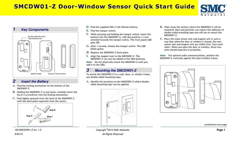
SMC Networks SMCDW01-Z User manual

SMC Networks

SMC Networks SMCDW01-Z User manual

SMC Networks PSE56 Series User manual

SMC Networks

SMC Networks PSE56 Series User manual

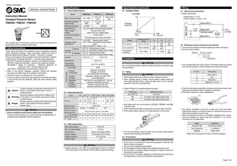
SMC Networks PSE541 User manual

SMC Networks

SMC Networks PSE541 User manual

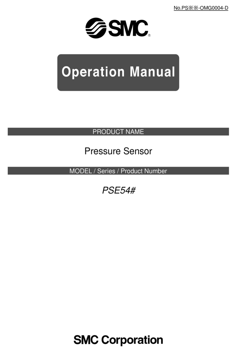
SMC Networks PSE54 Series User manual

SMC Networks

SMC Networks PSE54 Series User manual

Popular Security Sensor manuals by other brands

Olympus EPOCH 650 Getting started guide

Olympus

Olympus EPOCH 650 Getting started guide

GJD D-TECT R Ricochet GJD850R manual

GJD

GJD D-TECT R Ricochet GJD850R manual

Petzl VIZEN manual

Petzl

Petzl VIZEN manual

ZBL Science & Technology ZBL-R800 Operation manual

ZBL Science & Technology

ZBL Science & Technology ZBL-R800 Operation manual

iRay Technology Mars1717XF Series user manual

iRay Technology

iRay Technology Mars1717XF Series user manual

SILENTRON 5514 SILENT Dual Tech manual

SILENTRON

SILENTRON 5514 SILENT Dual Tech manual

SKF LINCOLN Magnetic sensor M G Series Service manual

SKF

SKF LINCOLN Magnetic sensor M G Series Service manual

Mobeye CMVXI-R user manual

Mobeye

Mobeye CMVXI-R user manual

Tecnoalarm MINIEXPLORER manual

Tecnoalarm

Tecnoalarm MINIEXPLORER manual

DANLERS CBU-HBND IP66 quick guide

DANLERS

DANLERS CBU-HBND IP66 quick guide

National Instruments SCC-RTD01 user guide

National Instruments

National Instruments SCC-RTD01 user guide

IFM R1D Series operating instructions

IFM

IFM R1D Series operating instructions

Black Diamond Equipment JETFORCE PRO instructions

Black Diamond Equipment

Black Diamond Equipment JETFORCE PRO instructions

V-TAC VT-81001 instruction manual

V-TAC

V-TAC VT-81001 instruction manual

Solinst 301 user guide

Solinst

Solinst 301 user guide

Watersavers WLDS-10 Mk3 Installation & commissioning

Watersavers

Watersavers WLDS-10 Mk3 Installation & commissioning

Sealey PP4.V2 instructions

Sealey

Sealey PP4.V2 instructions

Faraday 8842 installation instructions

Faraday

Faraday 8842 installation instructions

manuals.online logo
manuals.online logoBrands
  • About & Mission
  • Contact us
  • Privacy Policy
  • Terms and Conditions

Copyright 2025 Manuals.Online. All Rights Reserved.