Smeg CA61VM User manual

Contents
32
1INSTRUCTIONS FOR SA
F
ETY AND US
E
_
_______________________________
_
___3
3
2INSTALLING THE APPLIANCE_____________________________________________35
3ADAPTATION TO DIFFERENT TYPES OF GAS _______________________________39
4FINAL OPERATIONS ____________________________________________________44
5DESCRIPTION OF THE CONTROLS ON THE FRONT PANEL____________________46
6USING THE HOB________________________________________________________48
7USING THE OVEN ______________________________________________________51
8ELECTRONIC PROGRAMMER (ONLY ON MODELS WITH THE RELEVANT FUNCTION)
5
9DIGITAL TIMER (ONLY ON MODELS WITH THE RELEVANT FUNCTION) __________57
10 ANALOGUE CLOCK (ONLY ON MODELS WITH THE RELEVANT FUNCTION) ______57
11 CLEANING AND MAINTENANCE ___________________________________________58
12 EXTRAORDINARY MAINTENANCE _________________________________________60
THESE INSTRUCTIONS ARE VALID ONLY FOR THE DESTINATION COUNTRIES WHOSE
IDENTIFYING SYMBOLS ARE INCLUDED ON THE COVER OF THIS MANUAL.
INSTRUCTIONS FOR THE INSTALLER: these are intended for the qualified technician who must
carry out an adequate inspection of the gas system, install the appliance, set it functioning and test it.
INSTRUCTIONS FOR THE USER: these contain user advice, a description of the commands and the
correct procedures for cleaning and maintenance of the appliance.

Presentation
33
1INSTRUCTIONS FOR SAFETY AND USE
THIS MANUAL IS AN INTEGRAL PART OF THE APPLIANCE. THEREFORE IT MUST BE KEPT IN
ITS ENTIRETY AND IN AN ACCESSIBLE PLACE FOR THE WHOLE WORKING LIFE OF THE
COOKER. WE ADVISE YOU TO READ THIS MANUAL AND ALL THE INFORMATION IT
CONTAINS CAREFULLY BEFORE USING THE COOKER. ALSO KEEP THE SERIES OF
NOZZLES PROVIDED. INSTALLATION MUST BE CARRIED OUT BY QUALIFIED PERSONNEL IN
ACCORDANCE WITH THE REGULATIONS IN FORCE. THIS APPLIANCE IS INTENDED FOR
DOMESTIC USE AND CONFORMS TO THE EEC DIRECTIVES CURRENTLY IN FORCE. THE
APPLIANCE HAS BEEN BUILT TO CARRY OUT THE FOLLOWING FUNCTIONS: COOKING AND
HEATING UP FOOD; ALL OTHER USES SHOULD BE CONSIDERED UNSUITABLE.
THE MANUFACTURER CANNOT BE HELD LIABLE FOR USES OTHER THAN THOSE
INDICATED.
NEVER LEAVE DISCARDED PACKAGING UNATTENDED IN THE HOME.
SEPARATE WASTE PACKAGING MATERIALS BY TYPE AND CONSIGN THEM TO THE
NEAREST SORTED COLLECTION CENTRE.
IT IS OBLIGATORY FOR ALL ELECTRICAL SYSTEMS TO BE GROUNDED ACCORDING TO THE
METHODS REQUIRED BY SAFETY LEGISLATION.
THE PLUG TO BE CONNECTED TO THE POWER SUPPLY CABLE AND ITS SOCKET MUST BE
OF THE SAME TYPE AND CONFORM TO THE REGULATIONS IN FORCE.
THE SOCKET MUST BE ACCESSIBLE AFTER THE APPLIANCE HAS BEEN BUILT-IN.
NEVER UNPLUG BY PULLING ON THE CABLE.
IMMEDIATELY AFTER INSTALLATION, CARRY OUT A QUICK TEST ON THE APPLIANCE
FOLLOWING THE INSTRUCTIONS PROVIDED LATER IN THIS MANUAL. SHOULD THE
APPLIANCE NOT FUNCTION, DISCONNECT IT FROM THE POWER SUPPLY AND CALL THE
NEAREST TECHNICAL SUPPORT CENTRE.
NEVER ATTEMPT TO REPAIR THE APPLIANCE.
ALWAYS CHECK THAT THE CONTROL KNOBS ARE IN THE (OFF) POSITION WHEN YOU
FINISH USING THE APPLIANCE.
NEVER PLACE FLAMMABLE OBJECTS IN THE OVEN: IF IT SHOULD ACCIDENTALLY BE
SWITCHED ON, THIS MIGHT CAUSE A FIRE.
THE IDENTIFICATION PLATE WITH THE TECHNICAL DATA, SERIAL NUMBER AND MARK IS IN
A VISIBLE POSITION INSIDE THE STORAGE COMPARTMENT.
DO NOT REMOVE THIS PLATE FOR ANY REASON.
NEVER PLACE PANS WITH BOTTOMS WHICH ARE NOT PERFECTLY FLAT AND SMOOTH ON
THE HOB RACKS.
NEVER USE PANS OR GRIDDLES WHICH PROJECT BEYOND THE OUTSIDE EDGE OF THE
HOB.
HOLD THE GLASS LID WITH YOUR HAND WHILE LOWERING IT.
WARNING: THE GLASS LID CAN SPLINTER IF OVERHEATED.
TURN OFF ALL THE BURNERS AND WAIT FOR THEM TO COOL DOWN BEFORE CLOSING IT.

Presentation
34
DURING USE THE APPLIANCE BECOMES VERY HOT. TAKE CARE NEVER TO TOUCH THE
HEATING ELEMENTS INSIDE THE OVEN.
THE APPLIANCE IS INTENDED FOR USE BY ADULTS. DO NOT ALLOW CHILDREN TO GO
NEAR IT OR PLAY WITH IT.
WHEN THE GRILL IS WORKING THE ACCESSIBLE PARTS CAN BECOME VERY HOT: KEEP
CHILDREN AWAY.
IF THE APPLIANCE IS PLACED ON A PEDESTAL, IT MUST BE INSTALLED SO THAT IT
CANNOT SLIDE OFF.
IF THE COOKING PRODUCTS ARE INSTALLED ON MOTOR VEHICLES (FOR EXAMPLE,
CAMPERS, CARAVANS ETC.) THEY MUST ONLY BE USED WHEN THE VEHICLE IS STOPPED.
INSTALL THE PRODUCT SO THAT WHEN OPENING THE DRAWERS AND DOORS OF UNITS
POSITIONED AT THE LEVEL OF THE HOB THERE IS NO POSSIBILITY OF MAKING CONTACT
WITH PANS POSITIONED ON TOP OF IT.
THIS APPLIANCE IS MARKED ACCORDING TO EUROPEAN DIRECTIVE 2002/96/EC ON
WASTE ELECTRICAL AND ELECTRONIC EQUIPMENT (WEEE).
THIS DIRECTIVE DEFINES THE STANDARDS FOR THE COLLECTION AND RECYCLING OF
WASTE ELECTRICAL AND ELECTRONIC EQUIPMENT APPLICABLE THROUGHOUT THE
EUROPEAN UNION.
BEFORE THE APPLIANCE IS PUT INTO OPERATION, ALL LABELS AND PROTECTIVE FILMS
APPLIED INSIDE OR OUTSIDE MUST BE REMOVED.
The manufacturer cannot be held liable for damage to persons or things caused by failure to
comply with the above requirements or by tampering with any part of the appliance or by the use of
non-original spare parts.

Instructions for the installer
35
2INSTALLING THE APPLIANCE
The appliance must be installed by a qualified technician and according to the regulations in force.
Depending on the type of installation, it belongs to class 1 (Fig.A) or to class 2, subclass 1 (Fig.B-C).
This appliance may be installed next to walls, one of which must be higher than the appliance, at a
minimum distance of 50 mm from the side of the appliance, as shown in drawings A and B relative to
the installation classes. Any wall cupboards or ventilation hoods must be at a distance of at least 750
mm above the work surface.
AB
Built-in appliance Free-standing installation
AB
Built-in appliance Free-standing installation
C
Appliances equipped with a gas cylinder compartment and electric oven can only be
installed as free-standing (see fig. B).

Instructions for the installer
36
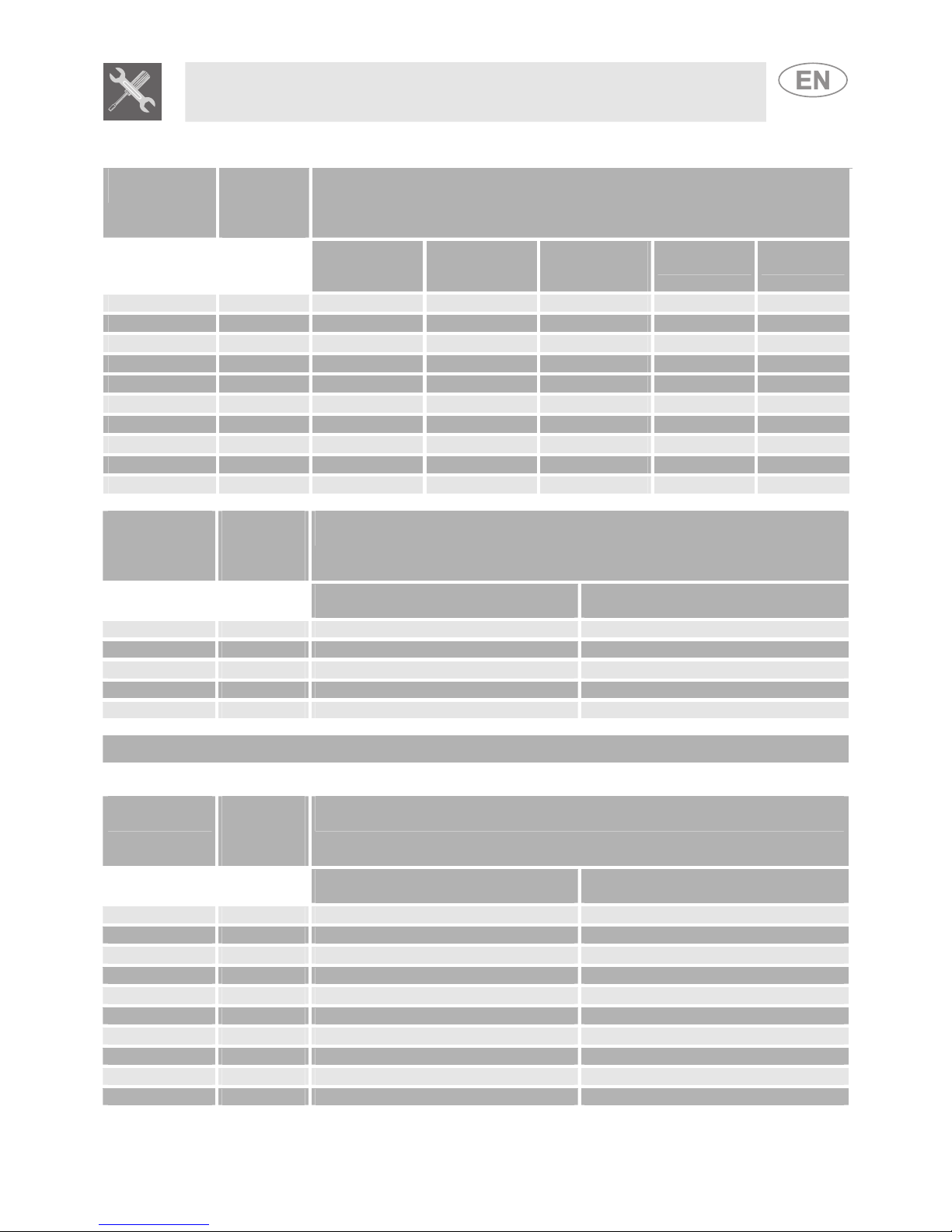
2.1 Electrical connection
Make sure the voltage and the cross-section of the power supply line match the specifications
indicated on the identification plate positioned in the storage compartment.
Do not remove this plate for any reason.
If the appliance is connected to the power supply network by means of a fixed connection, install a
multipolar cut-out device on the power supply line, with a contact opening distance equal to or
greater than 3 mm, located near the appliance and in an easily reachable position.
Connection to the power supply network may be fixed or with a plug and socket. In the latter case
the plug and socket must be suitable for the cable employed and conform to the regulations in force.
Regardless of the type of connection, the appliance must be earthed. Before connection, make sure
that the power supply line is suitably earthed. Avoid the use of adapters and shunts.
1 - For operation on 220-240V
∼
:use a three-pole cable of the
H05RR-F or H05V2V2-F type:
3 x 2.5 mm2(for 90 cm models)
3 x 1.5 mm2(for 50 and 60 cm models).
2 - For operation on 380-415V2N
∼
(only for 90 cm models):
use a four-pole cable of the H05RR-F or H05V2V2-F type
(cable with a cross-section of 4 x 1.5 mm2)
3 - For operation on 380-415V3N
∼
(only for 90 cm models):
use a five-pole cable of the H05RR-F or H05V2V2-F type
(cable with a cross-section of 5 x 1.5 mm2)
The end to be connected to the appliance must have an earth
wire (yellow-green) at least 20 mm longer than the others.
WARNING: THE VALUES INDICATED ABOVE REFER TO THE CROSS-SECTION OF THE
INTERNAL CONDUCTOR.
Warning: only some of the 90 cm models can be connected with two or three phases.
2.2 Room ventilation
The room containing the appliance should have a permanent air supply in accordance with the
standards in force. The room where the appliance is installed must have enough air flow for the
regular combustion of gas and for the air exchange needed in the room itself. The air vents,
protected by grills, must be suitably dimensioned in compliance with the current regulations and
positioned so that no part of them is obstructed.
The cooker must be kept adequately ventilated in order to eliminate the heat and humidity produced
by cooking: in particular, after prolonged use, you are recommended to open a window or to
increase the speed of any fans.

Instructions for the installer
37
2.3 Extraction of the combustion products
The combustion products must be extracted by means of hoods connected to a natural draught
chimney whose efficiency is certain or via forced extraction. An efficient extraction system requires
precision planning by a specialist qualified in this area and must comply with the positions and
distances indicated by the applicable standards. When the job is complete, the installer must issue a
certificate of conformity.
2.4 Connection to gas
2.4.1 Connection with a rubber hose
Installation with a standards-compliant rubber hose must be carried out so that the length of the
piping does not exceed 1.5 metres; make sure that the hose does not come into contact with moving
parts and that it is not crushed in any way. The inside diameter of the hose must be 8 mm for
LIQUID GAS and 13 mm for NATURAL GAS and CITY GAS.
Verify that all the following conditions are met:
•the hose is fixed to the hose connection with safety clamps;
•no part of the hose is in contact with the hot walls (max. 50°C);
•the hose is not under traction or tension and has no tight curves or twists;
•the hose is not in contact with sharp objects or sharp corners;
•if the hose is not perfectly airtight and leaks gas, do not try to repair it: replace it with a new
hose;
•verify that the hose is not past its expiry date (serigraphed on the hose itself).
CONNECTION USING RUBBER HOSES COMPLYING WITH THE CURRENT REGULATIONS IS
ONLY PERMITTED IF THE HOSE CAN BE INSPECTED ALONG ITS ENTIRE LENGTH.
2.4.2 Connection to natural and city gas
Make the connection to the gas mains using a rubber hose whose specifications
comply with the current regulations (verify that the reference standard is stamped
on the hose).
Carefully screw the hose connector A to the gas connector B of the appliance,
placing the seal Cbetween them. Push the rubber hose D onto the hose
connector A and secure it with the clamp E that is compliant with the applicable
standard.

Instructions for the installer
38
2.4.3 Connection to the gas cylinder in the internal compartment of the appliance (only on
some models)
Open the side compartment and insert a gas cylinder of
max. 15 kg. Push one end of the hose onto the hose
connector and secure it with one of the two clamps
provided. Insert the hose into the gas cylinder
compartment via the hole located at the back of the
appliance following the diagram shown to the side. Push
the other end onto the pressure regulator of the gas
cylinder; secure it in place using the second clamp
provided. Check for any leaks using a soapy solution,
never with a flame.
For the connection between the cooker and the gas cylinder use a piece of standards-compliant
hose no less than 1.4 m in length.
2.4.4 Connection to liquid gas
Use a standards-compliant pressure regulator and carry out the connection to the gas cylinder in
accordance with the regulations in force.
Make sure that the supply pressure complies with the values indicated in the paragraph “3.2/3.3
Burner and nozzle characteristics table”.
Screw the small hose connector F onto the large hose connector A;
connect the block thus obtained to the gas connector B (or use the hose
connector G which must be connected directly to the gas connector B)
and place the seal Cin between them. Push the end of the rubber hose
H onto the hose connector A+F (or G) and onto the outlet connection of
the pressure reducer on the gas cylinder. Secure the end of the hose H
to the hose connector A+F (or G) with the standards-compliant clamp I.
The hose connector Gillustrated is not supplied with the appliance. Only use standards-compliant
hose connectors.
2.4.5 Connection with a flexible steel hose (for all types of gas)
This type of connection can be made on both built-in and free-standing
appliances. Only use standards-compliant steel hoses whose length is
no greater than 2 metres. Screw the end of the flexible hose Lonto the
threaded ½” external gas connector B (ISO 228-1), with the seal C
positioned in between them.
At the end of the installation, check for any leaks with a soapy
solution, never with a flame.

Instructions for the installer
39
3ADAPTATION TO DIFFERENT TYPES OF GAS
Before carrying out the following operations, disconnect the appliance from the electricity supply.
The appliance is preset for natural gas G20 (2H) at a pressure of 20 mbar. In the case of operation
with other types of gas, the burner nozzles must be changed and the minimum flame adjusted on the
gas taps. In addition, in the case of the gas oven burner, the primary air must be regulated (3.4.2
Primary air adjustment for the oven burner). To change the nozzles, proceed as described in the
following paragraphs.
3.1 Replacement of the cooking hob nozzles
1. Extract the pan racks and remove all the caps and flame-spreader crowns;
2. Unscrew the burner nozzles with a 7 mm socket wrench;
3. Replace the burner nozzles according to the gas to be used (see paragraph “3.2/3.3 Burner and
nozzle characteristics table”).
4. Replace the burners in the correct position.
The nozzles for using city gas (G110 – 8 mbar) are available from authorised service centres.

Instructions for the installer
40
3.2 Burner and nozzle characteristics table (60 cm model)
Burner
Rated
heating
capacity
(kW)
LIQUID GAS – G30/G31 30/37 mbar
Nozzle
diameter
1/100 mm
By-pass
mm
1/100
Reduced
capacity
(W)
Capacity
g/h G30 Capacity
g/h G31
Auxiliary 1.0 50 30 350 73 71
Semi-rapid 1.8 65 33 450 131 129
Rapid (3) 3.0 85 45 800 218 214
Rapid (5) 2.5 79 45 800 182 179
Triple crown 3.2 91 65 1500 233 229
Oven 3.2 87 50 900 233 229
Grill 2.9 87 // // 211 207
Burner
Rated
heating
capacity
(kW)
CITY GAS – G110 8 mbar
Nozzle
diameter 1/100 mm
Reduced capacity
(W)
Auxiliary 1.0 145 350
Semi-rapid 1.8 185 450
Rapid (3) 3.0 260 800
Rapid (5) 2.5 230 800
Triple crown 3.5 290 1200
Oven 3.2 270 900
Grill 2.9 270 //
The values for city gas refer to appliances in category III 1a2H3+.
Burner
Rated
heating
capacity
(kW)
NATURAL GAS – G20 20 mbar
Nozzle
diameter 1/100 mm
Reduced capacity
(W)
Auxiliary 1.0 72 350
Semi-rapid 1.8 97 450
Rapid (3) 3.0 115 800
Rapid (5) 2.5 108 800
Triple crown 3.5 133 1500
Oven 3.2 130 900
Grill 2.9 130 //

Instructions for the installer
41
3.3 Burner and nozzle characteristics table (90 cm model)
Burner
Rated
heating
capacity
(kW)
LIQUID GAS –G30/G31 30/37 mbar
Nozzle
diameter
1/100 mm
By-pass
mm
1/100
Reduced
capacity
(W)
Capacity
g/h G30
Capacity
g/h G31
Auxiliary 1 50 30 350 73 71
Semi-rapid 1.8 65 33 450 131 129
Rapid 3 85 45 800 218 214
Triple crown (4) 3.2 91 65 1500 233 229
Triple crown (8) 3.5 94 65 1500 255 250
Fish kettle 1.9 68 45 800 138 136
Oven 3.2 87 50 900 233 229
Maxi oven 5.2 110 59 1300 378 372
Grill 2.9 87 // // 211 207
Maxi grill 4.0 100 // // 291 286
Burner
Rated
heating
capacity
(kW)
CITY GAS –G110 8mbar
Nozzle diameter
1/100 mm
Reduced capacity
(W)
Auxiliary 1 145 350
Semi-rapid 1.8 185 450
Rapid 3 260 800
Triple crown 3.5 290 1200
Fish kettle 1.9 190 800
Gas G110 cannot be used in gas oven models.
The values for city gas refer to appliances in category III 1a2H3+.
Burner
Rated
heating
capacity
(kW)
NATURAL GAS –G20 20 mbar
Nozzle diameter
1/100 mm
Reduced capacity
(W)
Auxiliary 1 72 350
Semi-rapid 1.8 97 450
Rapid 3 115 800
Triple crown (4) 3.5 133 1500
Triple crown (8) 3.5 140 1500
Fish kettle 1.9 94 800
Oven 3.2 130 850
Maxi oven 5.2 164 1200
Grill 2.9 130 //
Maxi grill 4.0 150 //

Instructions for the installer
42
3.4 Arrangement of the burners on the hob
BURNERS
1. Auxiliary
2. Semi-rapid
3. Rapid (60 X 60)
4. Triple crown
5. Rapid (60 X 50)
3.5 Arrangement of the burners on the hob
BURNERS
1Auxiliary
2Semi-rapid
3Rapid
4Triple crown
5Large electric plate
(1500W)
6Small electric plate
(1500W)
7Fish kettle
8Triple crown

Instructions for the installer
43
3.6 Oven burner adjustment (only for models with a gas oven)
To adjust the oven burner you need to open the oven door and carry out
the following operations:
•Remove the oven basin and its rack.
•Lift up the oven surface and pull it outwards.
3.6.1 Replacing the oven + grill burner nozzle
•Loosen the oven burner fixing screw A.
•Push the burner B towards the right until the nozzle
is accessible.
•Using a 13 socket wrench, replace the nozzle,
inserting a new nozzle suitable for the type of gas to
be used (see paragraph “3.2/3.3 Burner and nozzle
characteristics table”).
3.6.2 Primary air adjustment for the oven + grill burner
•Loosen the adjustment screw “A” of the air regulation sleeve.
•Turn the adjustment sleeve “B” to the position that corresponds to the type
of gas to be used according to the table below.
•Tighten the adjustment screw and restore the seals.
•When the operation is completed, reassemble the burner correctly.
NATURAL GAS G30/G31 (GPL) G30/G31 (GPL) G 110 – CITY GAS
(N) 60-cm oven 90-cm oven 60-cm oven only
OVEN X = 5 mm 10 mm 10 mm 3 mm
GRILL X = 5 mm 15 mm 10 mm 3 mm

Instructions for the installer
44
4FINAL OPERATIONS
After replacing the nozzles, reposition the flame-spreader crowns, the burner caps and the racks.
Following adjustment to a gas other than the preset one, replace the gas adjustment label fixed to
the appliance with the one corresponding to the new gas. The label is inserted inside the pack
together with the nozzles.
4.1 Adjusting the hob burner minimum for city and natural gas
Light the burner and turn it to the minimum position . Extract the gas
tap knob and turn the adjustment screw at the side of the tap rod until the
correct minimum flame is achieved.
Refit the knob and verify that the burner flame is stable (when turning the
knob rapidly from the maximum to the minimum position the flame must
not go out). Repeat the operation on all the gas taps.
For valved models, keep the knob pressed in at the minimum level for a few seconds to keep the
flame lit and to activate the safety device.
4.2 Regulation of the hob burner minimum for liquid gas
In order to adjust the minimum setting with liquid gas, the screw at the side of the tap rod must be
tightened clockwise all the way.
The diameters of the by-passes for the individual burners are given in the paragraph “3.2/3.3 Burner
and nozzle characteristics tables”. When the adjustment is completed, restore the sealing of the by-
passes with paint or another material.
4.3 Adjustment of the oven burner minimum
The oven thermostat is equipped with a screw for regulating the minimum, which can be seen by
removing the thermostat knob.
When changing the type of supplied gas, the minimum must be adjusted as follows:
•Light the oven burner and keep it at the maximum for 10/15 minutes with the door closed and
without the shelf; after this period, move the knob to the minimum temperature, slide off the knob
and insert a straight edge screwdriver to make the adjustment.
•If using liquid gas the adjustment screw must be tightened clockwise to the very end. The
diameter of the by-pass is given in paragraph “3.2/3.3 Burner and nozzle characteristics tables”.
•If using city gas or natural gas, adjust the screw so that when the thermostat knob is turned from
the maximum to the minimum position, the flame remains steady and constant. When the
adjustment is completed, restore the seal on the screws using paint or equivalent materials.
When closing the oven door, make sure the burner remains lit at the minimum.

Instructions for the installer
45
4.4 Assembling the skirt (on certain models only)
•Loosen the nuts B.
•Position the skirt above the top, taking care to align the pins C with the holes D.
•Secure the skirt to the top by tightening screws A.
4.5 Positioning and levelling the appliance
After making the electrical and gas connections, level the appliance on the floor by means of its four
adjustable feet. For good cooking results, the appliance must be properly levelled.
Depending on the model you have purchased, the feet height adjustment may vary from 70 to 95
mm and from 110 to 160 mm. These heights refer to the distance between the highest point of the
foot (fixed part) and the lowest point (movable part which rests on the floor).

Instructions for the user
46
5DESCRIPTION OF THE CONTROLS ON THE FRONT PANEL
All the cooker controls are grouped together on the front panel. The symbols used are described in the
table below.
FRONT RIGHT-HAND BURNER
CENTRAL BURNER
REAR RIGHT-HAND BURNER GAS OVEN THERMOSTAT
OVEN / ROTISSERIE GRILL LAMP
SWITCH
REAR LEFT-HAND BURNER
FRONT LEFT-HAND BURNER ELECTRIC OVEN THERMOSTAT
REAR CENTRAL BURNER ELECTRIC OVEN FUNCTIONS KNOB
FRONT CENTRAL BURNER
If the cooker is equipped with an electronic programmer, before using the oven make sure that
appears on the display; see “8.1 Setting the time”.
HOB BURNERS CONTROL KNOB
To light the flame, press the knob and turn it anticlockwise to the minimum
flame symbol . To adjust the flame, turn the knob to the zone between the
maximum ( ) and minimum ( ) settings. To turn off the burner, turn the knob
to the position.
GAS OVEN THERMOSTAT KNOB
(ONLY ON MODELS WITH THE RELEVANT FUNCTION)
This knob allows the gas burner inside the oven to be lit. The cooking
temperature is selected by turning the knob anticlockwise to the desired setting,
between Min. and 275°C.
To learn how to light the gas oven, see the paragraph “7.3 Uso del forno a gas”
OVEN / ROTISSERIE GRILL LIGHT SWITCH KNOB
(ONLY ON MODELS WITH THE RELEVANT FUNCTION)
This knob enables the Grill / Rotisserie function to be activated or the light
inside the oven to be lit to check the cooking progress of the food.
WARNING: IT IS NOT POSSIBLE TO OPERATE THE GAS OVEN AND THE
GRILL / ROTISSERIE AT THE SAME TIME.

Instructions for the user
47
ELECTRIC OVEN THERMOSTAT KNOB
(ONLY ON MODELS WITH THE RELEVANT FUNCTION)
The cooking temperature is selected by turning the knob clockwise to the
desired setting, between 50°C and 260°C.
The orange light comes on to indicate that the oven is heating up. When this
light goes out, the preset heating temperature has been reached. When the
light flashes regularly it means that the temperature inside the oven is kept
steady on the set level.
STATIC ELECTRIC OVEN FUNCTIONS KNOB
(ONLY ON MODELS WITH THE RELEVANT FUNCTION)
The electric oven's various functions are suitable for different cooking modes.
After selecting the desired function, set the cooking temperature using the
thermostat knob.
WIDE GRILL FUNCTION
OVEN LIGHT
GRILL FUNCTION
STATIC OVEN FUNCTION
GRILL + ROTISSERIE FUNCTION (IN
MODELS EQUIPPED WITH A
ROTISSERIE)
LOWER HEATING ELEMENT
FUNCTION
ELECTRIC FAN OVEN FUNCTIONS KNOB
(ONLY ON MODELS WITH THE RELEVANT FUNCTION)
The electric oven's various functions are suitable for different cooking modes.
After selecting the desired function, set the cooking temperature using the
thermostat knob.
FAN-ASSISTED GRILL FUNCTION
OVEN LIGHT
FAN-ASSISTED LOWER HEATING
ELEMENT FUNCTION
STATIC OVEN FUNCTION
FAN OVEN FUNCTION
GRILL FUNCTION
TIMER KNOB
(ONLY ON MODELS WITH THE RELEVANT FUNCTION)
In order to use the timer, the buzzer must be set by turning the knob in a
clockwise direction. The numbers correspond to minutes (maximum 55
minutes). Adjustment is progressive and intermediate positions between the
figures can be used. The end of cooking buzzer does not interrupt operation of
the oven.

Instructions for the user
48
6USING THE HOB
6.1 Lighting the hob burners
Before lighting the hob burners, check that the flame-spreader crowns are correctly in place with
their respective burner caps, making sure that the holes A in the flame-spreaders are aligned with
the igniters and thermocouples.
Before lighting the burners, lift the glass lid; before closing it again, turn off all the burners and wait
for them to cool.
The optional rack B is for use with woks.
To prevent damage to the cooking hob, the cooker comes complete with a raised rack Cfor use
underneath pans more than 26 cm in diameter.
The reduction C supplied is for use with small pans as well.
The burner controlled by each knob is shown next to the knob.
The appliance is equipped with an electronic ignition device. Simply press the
knob and turn it anticlockwise to the minimum flame symbol , until it lights. If
it does not light in the first 15 seconds, position the knob on 0 and wait at least
60 seconds before trying to light it again.
On valved models, once the burner is lit, keep the knob pressed for a few
seconds to give the thermocouple time to heat up. The burner may go out when
the knob is released: in this case, the thermocouple has not heated up
sufficiently.
Wait a few moments and repeat the operation keeping the knob pressed for
longer. This is not necessary on burners that are not equipped with a
thermocouple.
On models with a thermocouple, if the burners should go out accidentally a safety device will be
tripped, cutting off the gas supply even if the gas tap is open. In this case, turn the knob to the OFF
position and wait at least 60 seconds before trying to light the burner again.
6.2 Practical hints for using the hob burners
For better burner efficiency and to minimise gas consumption: use pans with lids and of a suitable
size for the burner, so that flames do not reach up the sides of the pan (see paragraph “6.3 Pan
Diameters”). Once the contents come to the boil, turn down the flame far enough to ensure that the
liquid does not boil over. To prevent burns or damage to the hob during cooking, all pans or griddles
must be placed inside the perimeter of the hob. All pans must have smooth, flat bottoms. Take the
greatest care when using fats or oils since they may catch fire if overheated. If the flame accidentally
goes out, turn off the control knob and wait at least 1 minute before trying to re-light the burner.

Instructions for the user
49
6.3 Pan diameters (60 cm model)
BURNERS min. and max.
Ø (in cm)
BURNERS min. and max.
Ø (in cm)
(60 X 50) (60 X 60)
1. Auxiliary 1. Auxiliary12 – 14 12 – 14
2. Semi-rapid 2. Semi-rapid16 – 22 16 – 24
5. Rapid
3. Rapid18 – 24 18 – 26
4. Triple crown 18 – 26
6.4 Pan diameters (90 cm model)
BURNERS
min. and max.
Ø (in cm)
1. Auxiliary 12 – 14
2. Semi-rapid 16 – 24
3. Rapid 18 – 26
4. Triple crown 18 – 26
7. Fish kettle Suitable oval
containers
8. Triple crown 18 - 26

Instructions for the user
50
6.5 Switching on the electric plate
6.5.1 Switching on electric plates
Some models have plates with different diameters. These are controlled by a selector; to switch
them on, turn the knob to the desired position. There is a diagram serigraphed on the front panel
above each knob showing which plate each knob refers to. A red indicator light signals that the
plates have been switched on.
6.5.2 How to use the electric plates
The rapid plates offer the benefit of ultra-rapid cooking. For illustrative purposes only, a regulation
table for the plates is included.
RAPID PLATES
HEAT INTENSITY
POSSIBLE TYPES OF COOKING
0 Off -
1 Dim To melt butter, chocolate etc.
To heat up small amounts of liquid.
2 Soft To heat up larger amounts of liquid.
3 Slow To thaw frozen foods and to prepare stews, cook
at boiling point or just below it.
4 Medium To cook foods that have to be brought to the boil;
for delicate meat roasts and fish.
Strong For roasts, chops, steaks and large-scale boiling.
5
To boil large quantities of water, to fry.
6 High
PRECAUTIONS
When the plate is switched on for the first time or if it has not been used for a
long time, you must first eliminate any humidity that may have been absorbed
by the insulating coating; to dry it out, leave the plate on for 30 minutes at
position 1 on the selector knob.
For correct use remember:
Only switch on the plate after you have positioned the pan on top of it.
•Use pans with a smooth bottom and a thick base.
•Never use pans that are smaller than the plate.
•Dry the bottom of the pan before putting it down on the plate.
•After use, to keep it in good condition and make sure that the surface is
always clean and shiny, the electric plate must be treated with the
appropriate products that can be bought from shops. This necessary
operation avoids any oxidation (rust).
•When cooking food with oil or fat, which are highly flammable, never leave
the appliance unattended.
•Even after use the plates stay hot for a long time: to avoid getting burned,
do not place your hand or other objects on top of them.
•Before switching on the electric plates, lift the glass cooker lid; before
closing it again, turn off all the plates and wait for them to cool down.
•As soon as you notice a crack on the surface of the plates, immediately
disconnect the appliance from the mains supply and contact the nearest
authorised technical assistance centre.

Instructions for the user
51
7USING THE OVEN
In models with an electronic programmer, before using the oven make sure that is on the display.
In models with an analogue clock and a timer knob, it should be set to .
7.1 Warnings and general advice
Before using the oven and the grill for the first time, pre-heat to their maximum temperature (260°C
for electric ovens and 275°C for gas ovens) long enough to burn away any manufacturing oily
residues which could give the food a bad smell. After an interruption in the electricity supply, the
programmer display flashes at regular intervals. To make any adjustments, refer to “8
ELECTRONIC PROGRAMMER”.
The oven accessories intended to come into contact with food are made of materials that comply
with the provisions of Directive 89/109/EEC, dated 21/12/88, and of Legislative Decree 108, dated
25/01/92.
5 cm
WARNING: the gas oven must be lit with the oven door open. The oven is
equipped with a safety system that blocks ignition of the burner if the
door is closed. If you make a mistake in the lighting procedure, open the
oven door and wait a few minutes before trying to light it again.
To prevent any steam in the oven from causing problems, open the door in two
stages: half open (5 cm approx.) for 4-5 seconds and then fully open. If you
need to access the food, always leave the door open for as short a time as
possible to prevent the temperature in the oven from falling and ruining the
food.
DURING THE COOKING OF DESSERTS AND VEGETABLES, DRIPPING FROM THE BOTTOM OF
THE DOOR COULD OCCUR. THIS IS A NATURAL PHYSICAL PHENOMENON WHICH MAINL
Y
OCCURS WHEN PREHEATING HAS NOT TAKEN PLACE. TO AVOID THIS, OPEN THE DOOR A
COUPLE OF TIMES DURING COOKING, TAKING GREAT CARE.
7.2 Cooling system
The oven is equipped with a cooling system which automatically comes on a few minutes after the
oven is turned on. The fan causes a steady outflow of air from above the door which may continue
for a brief period of time even after the oven has been turned off.
7.3 Using the gas oven
7.3.1 Electronic spark ignition
Open the oven door fully, press the thermostat knob and turn it anticlockwise to
the maximum temperature; the electric spark ignition is activated automatically.
When the oven is lit, keep the knob pressed down for a few seconds to allow
the thermocouple to heat up.
If the burner does not ignite after 15 seconds, stop attempting to light it, open
the oven door completely and do not try to light it again for at least 1 minute.
7.3.2 Manual ignition
Open the oven door fully and turn the thermostat knob. Bring a lighted
match close to the mouth of flame pipe Aat the centre of the oven
surface and press the thermostat knob. Once it is lit, keep the knob
pressed down for a few seconds to allow the thermocouple to heat up
and make sure that it has remained lit by looking through inspection
hole B. The cooking temperature is selected by turning the knob
clockwise to the desired setting, between 50°C and 275°C.
If the burner is extinguished accidentally, turn the knob to the off position ( ) and wait at least one
minute before trying to light it again.
This manual suits for next models
32
Table of contents
Other Smeg Cooker manuals

Smeg
Smeg Classica SSA91MAX9 User manual

Smeg
Smeg Classica CX60ISVT9 User manual

Smeg
Smeg SSA60MX2 User manual

Smeg
Smeg SUK91CMX5 User manual

Smeg
Smeg SUK61CMA5 User manual

Smeg
Smeg SNL61MA9 User manual

Smeg
Smeg FS9608AS-1 User manual

Smeg
Smeg Concerto SX91MDS9 User manual

Smeg
Smeg CS120A-6 User manual

Smeg
Smeg CP60X User manual

Smeg
Smeg C9MAMBSSA2 User manual

Smeg
Smeg C9GMXA User manual

Smeg
Smeg CB66CES User manual

Smeg
Smeg CE9CMX User manual

Smeg
Smeg Classica CG90IANT9 User manual

Smeg
Smeg SA9065XS User manual

Smeg
Smeg C9IMMB2 User manual

Smeg
Smeg Mista Aesthetic B61GMXI9 User manual

Smeg
Smeg SUK61 User manual

Smeg
Smeg Portofino CPF92GMBL User manual