Smeg SNZ91MFA1 User manual

Table of Contents
3
1PRECAUTIONS FOR SAF
E
TY AND US
E
_
_______________________________
_
_____
4
2INSTALLING THE APPLIANCE______________________________________________6
3ADAPTING TO DIFFERENT TYPES OF GAS __________________________________9
4FINAL OPERATIONS ____________________________________________________12
5DESCRIPTION OF FRONT PANEL CONTROLS _______________________________14
6USING THE HOB________________________________________________________16
7USING THE OVEN ______________________________________________________17
8ELECTRONIC PROGRAMMER (ON SOME MODELS ONLY)_____________________21
9DIGITAL TIMER (ON SOME MODELS ONLY) _________________________________23
10 ANALOGUE CLOCK (ON SOME MODELS ONLY) _____________________________23
11 CLEANING AND MAINTENANCE ___________________________________________24
12 EXTRAORDINARY MAINTENANCE _________________________________________26
INSTRUCTIONS FOR THE INSTALLER: these are intended for the qualified engineer who is to chec
k
the gas supply system and install, commission and test the appliance.
INSTRUCTIONS FOR THE USER: these provide recommendations for use, a description of the control
s
and the correct procedures for cleaning and maintaining the appliance.

Presentation
4
1PRECAUTIONS FOR SAFETY AND USE
THIS MANUAL IS AN INTEGRAL PART OF THE APPLIANCE. TAKE GOOD CARE OF IT AND
KEEP IT TO HAND THROUGHOUT THE COOKER'S LIFE CYCLE. WE URGE YOU TO READ THIS
MANUAL AND ALL THE INFORMATION IT CONTAINS CAREFULLY BEFORE USING THE
COOKER. ALSO KEEP THE SET OF NOZZLES PROVIDED IN A SAFE PLACE. INSTALLATION
MUST BE CARRIED OUT BY QUALIFIED STAFF IN COMPLIANCE WITH THE RELEVANT
REGULATIONS. THIS APPLIANCE IS INTENDED FOR HOUSEHOLD USE AND COMPLIES WITH
THE EEC DIRECTIVES CURRENTLY IN FORCE. THE APPLIANCE IS BUILT TO PROVIDE THE
FOLLOWING FUNCTION: COOKING AND HEATING FOODS; ALL OTHER USES ARE TO BE
CONSIDERED IMPROPER.
THE MANUFACTURER DECLINES ALL LIABILITY FOR USES OTHER THAN THOSE STATED
ABOVE.
NEVER LEAVE PACKAGING RESIDUES UNATTENDED IN THE HOME.
SEPARATE WASTE PACKAGING MATERIALS BY TYPE AND CONSIGN THEM TO THE NEAREST
SEPARATE DISPOSAL CENTRE.
THE APPLIANCE MUST BE CONNECTED TO EARTH IN COMPLIANCE WITH ELECTRICAL
SYSTEM SAFETY REGULATIONS.
THE PLUG TO BE CONNECTED TO THE POWER SUPPLY LEAD AND THE RELATIVE SOCKET
MUST BE OF THE SAME TYPE AND COMPLY WITH THE RELEVANT REGULATIONS.
THE POWER SUPPLY SOCKET MUST BE ACCESSIBLE EVEN AFTER THE APPLIANCE HAS
BEEN BUILT-IN.
NEVER DISCONNECT THE PLUG BY PULLING ON THE POWER SUPPLY LEAD.
IMMEDIATELY AFTER INSTALLATION, CARRY OUT A QUICK TEST ON THE APPLIANCE
FOLLOWING THE INSTRUCTIONS PROVIDED LATER IN THIS MANUAL. IF THE APPLIANCE
FAILS TO OPERATE, DISCONNECT IT FROM THE ELECTRICAL MAINS AND CONTACT YOUR
NEAREST SERVICE CENTRE.
NEVER ATTEMPT TO REPAIR THE APPLIANCE.
AFTER EACH USE, ALWAYS CHECK THAT THE CONTROL KNOBS ARE TURNED TO THE
(OFF).
NEVER PLACE FLAMMABLE OBJECTS IN THE OVEN: IF IT SHOULD ACCIDENTALLY BE
SWITCHED ON, THIS MIGHT CAUSE A FIRE.
THE NAMEPLATE WITH THE TECHNICAL DATA, SERIAL NUMBER AND MARK IS IN A VISIBLE
POSITION INSIDE THE STORAGE COMPARTMENT.
THE NAMEPLATE MUST NEVER BE REMOVED
NEVER PLACE PANS WITH BOTTOMS WHICH ARE NOT PERFECTLY FLAT AND SMOOTH ON
THE HOB PAN STANDS.
NEVER USE PANS OR GRIDDLE PLATES WHICH PROJECT BEYOND THE OUTSIDE EDGE OF
THE HOB.

Presentation
5
ALWAYS KEEP HOLD OF THE HOB'S GLASS LID WHEN LOWERING IT.
WARNING: THE GLASS LID MAY SHATTER IF OVERHEATED.
TURN OFF ALL THE BURNERS AND WAIT FOR THEM TO COOL BEFORE CLOSING IT.
THE APPLIANCE BECOMES VERY HOT DURING USE. TAKE CARE NOT TO TOUCH THE
HEATING ELEMENTS INSIDE THE OVEN.
THE APPLIANCE IS INTENDED FOR USE BY ADULTS. KEEP CHILDREN AT A SAFE DISTANCE
AND NEVER ALLOW THEM TO PLAY WITH IT.
WHEN THE GRILL IS IN OPERATION, ACCESSIBLE PARTS MAY BECOME VERY HOT: KEEP
CHILDREN AT A SAFE DISTANCE.
IF THE APPLIANCE IS MOUNTED ON A STAND, IT MUST BE INSTALLED IN SUCH A WAY THAT
IT CANNOT SLIP OFF.
DO NOT SPRAY AEROSOLS IN THE VICINITY OF THIS APPLIANCE WHILE IT IS IN OPERATION.
THIS APPLIANCE IS DESIGNED FOR COOKING FOOD AND IT SHALL NOT BE USED AS A
SPACE HEATER.
REPLACED APPLIANCES MUST BE TAKEN TO A SPECIAL GARBAGE COLLECTION CENTRE.
BEFORE THE APPLIANCE IS PUT INTO OPERATION, ALL THE LABELS AND PROTECTIVE
FILMS APPLIED INSIDE OR OUTSIDE MUST BE REMOVED.
The manufacturer declines all responsibility for injury or damage caused by failure to comply wit
h
the above regulations or deriving from tampering with even just one part of the appliance and the us
e
of non-original spare parts.

Instructions for the Installer
6
2INSTALLING THE APPLIANCE
It is the law that all gas appliances are installed by authorised persons. Clearance aroun
d
the cooker must comply with the requirements of AS5601.
2.1 Electrical connection
Check that the voltage and size of the power supply line are as specified on the nameplate inside the
storage compartment.
This nameplate must never be removed.
If a permanent connection to the electrical mains is used, the appliance's power supply line must be
fitted with an omnipolar breaking device with contact breaking gap of at least 3 mm located in an
easily accessible position close to the appliance itself.
For operation on 220-240 V
∼
:use an H05RR-F or H05V2V2-F type
three-core cable (3 x 2.5 mm2).
For operation on 380-415 V 2N
∼
:use an H05RR-F or H05V2V2-F
type four-core cable (4 x 1.5 mm2).
For operation on 380-415 V 3N
∼
:use an H05RR-F or H05V2V2-F
type five-core cable (5 x 1.5 mm2).
The cable end to be connected to the appliance must be
provided with an earth wire (yellow-green) at least 20 mm
longer.
The manufacturer declines all responsibility for damage to persons or things caused by non-
observance of the above prescriptions or by interference with any part of the appliance.

Instructions for the Installer
7
Overall dimensions: location of gas and electrical connection points (all measures in mm).
A 60
B 410
C 60
D 70
2.2 Gas connection
This appliance is suitable for installation with Natural Gas or LPG (propane). Refer to
page 12 for the relevant burner pressure and appropriate injector sizes. When the
appliance is to be connected to Natural Gas then the pressure regulator supplied
must be fitted to the gas inlet. A test point (for checking the gas pressure) is supplied
either with the regulator or as a separate fitting in the case of LPG (propane)
appliances.
Connection of the appliance to the gas supply must be in accordance with the
requirements of AS5601. A ½” BSP connector at the inlet is recommended and the
gas supply line to the appliance must be of adequate length to allow sufficient
withdrawal of appliance for service or disconnection and be annealed copper pipe.
The cooker must be installed with provision to allow the gas to be turned off and
disconnected for servicing and removal of the appliance as required from the gas
supply.
Before the cooker is operated make certain all relevant parts are placed in the
correct position.
When the installation is completed the installation connections of cooker will require
to be leak tested, the burner operating pressure and flame checked and adjusted.
Warranty service calls do not cover these adjustments!
To check the operating pressure of the appliance it is recommended at least 2 large
size burners are used. Ensure appliance is secured to wall when installation is
completed.
N.G. The regulator supplied must be fitted to the ½ BSP thread at the rear of the
appliance. An approved manual shut-off valve must be installed. The N.G. regulator
must be checked and adjusted to 1.0kPa after installation.
L.P.G. Can be connected to the inlet fitting directly. The pressure must be
checked to ensure it is operating at 2.75kPa. A separate test point fitting must
be installed between the piping & the appliance for the pressure to be checked
to ensure it is operating at 2.75kPa.

Instructions for the Installer
8
2.3 Room ventilation
Caution – This cooker may only be installed and operated in rooms permanently ventilated
in accordance with current regulations. For proper operation of a gas appliance it is
essential for the air necessary for combustion of the gas to be able to flow naturally into the
room. Air must flow directly into the room through openings in its outside walls. This (these)
opening (s) must have a free passage cross-section of at least 100 cm2, or 200 cm2for
appliances not equipped with gas safety device. These openings must be constructed so
that they cannot be obstructed indoors or outdoors, and should preferably be close to the
floor on the side opposite to the combustion gas discharge point. If it is not possible to
make the openings in the room where the cooker is installed, the necessary air may be
taken from an adjoining room, proveded it is not a bedroom or a room with fire risk.
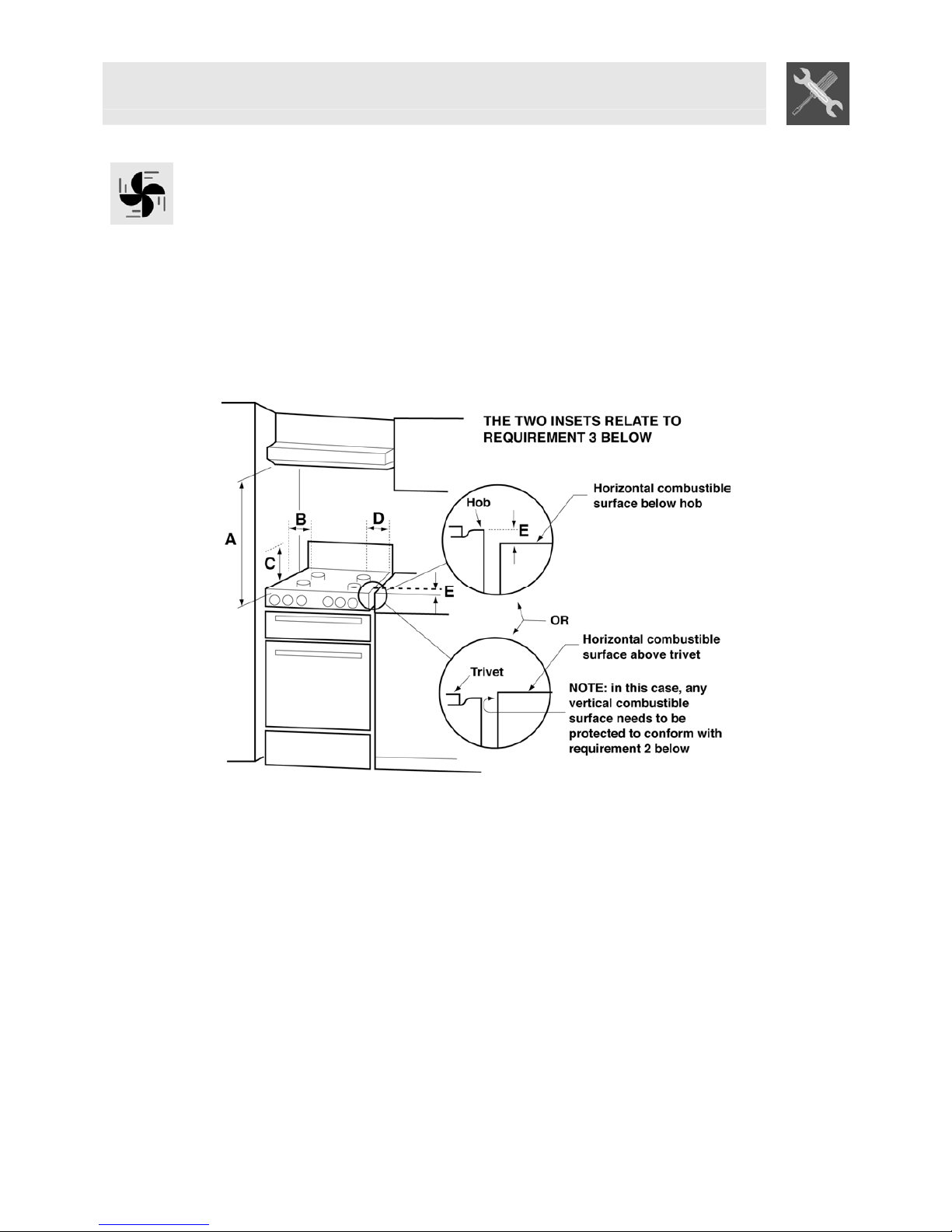
2.4 Clearance above and around domestic cookers
Extract from AS5601
REQUIREMENTS
1Overhead clearances – (Measurement A)
Range hoods and exhaust fans shall be installed in accordance with the manufacturer’s
instructions. However, in no case shall the clearance between the highest part of the hob of the
cooking appliance and a range hood be less than 600 mm or, for an overhead exhaust fan, 750
mm.
Any other downward facing combustible surface less than 600 mm above the highest part of the
hob shall be protected for the full width and depth of the cooking surface area in accordance with
Clause 5.12.1.2. However, in no case shall this clearance to any surface be less than 450 mm.
2Side clearances – (Measurements B& C)
Where B, measured from the periphery of the nearest burner to any vertical combustible surface, is
less than 200 mm, the surface shall be protected in accordance with Clause 5.12.1.2 to a height C
of not less than 150 mm above the hob for the full dimension (width or depth) of the cooking surface
area. Where the cooking appliance is fitted with a ‘splashback’, protection of the rear wall is not
required.
3Additional requirements for Freestanding and Elevated Cooking Appliaces – (Measurements D& E)
Where D, the distance from the periphery of the nearest burner to a horizontal combustible surface
is less than 200 mm, then Eshall be 10 mm or more, or the horizontal surface shall be above the
trivet. See insets above.

Instructions for the Installer
9
NOTES
1Requirement 3 does not apply to a freestanding or elevated cooking appliance which is
designed to prevent flames or the cooking vessels from extending beyond the periphery of
the appliance.
2The ‘cooking surface area’ is defined as that part of the appliance where cooking normally
takes place and does not include those parts of the appliance containing control knobs.
3For definition of hob, see Clause 1.4.64.
4For definition of trivet, see Clause 1.4.109.
5Consideration is to be given to window treatments when located near cooking appliances.
See Clause 5.3.4.
3ADAPTING TO DIFFERENT TYPES OF GAS
Before carrying out the operations described below, disconnect the appliance from the electricit
y
supply.
The hob of the cooker is adjusted for use with either natural gas at a pressure of 1.0kPa. If used with
other types of gas, you have to replace the nozzles, then adjust the minimum flame on the gas taps.
For nozzle replacement and burner adjustment operate as described in the following paragraph.
3.1 Changing the hob nozzles
1. Remove the pan stands, all the burner caps and the flame diffuser rings
2. Use a 7 mm socket wrench to unscrew the burner nozzles;
3. Replace the burner nozzles depending on the type of gas to be used (see point “3.2 Burner and
nozzle characteristics table").
4. Put the burners back into place correctly.

Instructions for the Installer
10
3.2 Burner and Nozzle Data Tables
Burner
Nominal
heat
capacity
(kW)
LPG (PROPANE)–2.75 KPa
Nozzle
diameter
1/100 mm
By-pass
mm
1/100
Reduced
heat capacity
(W)
Flow rate
g/h G30
Flow rate
g/h G31
Auxiliary 1 50 30 350 73 71
Semi-rapid 1.75 65 33 450 127 125
Rapid 3 85 45 800 218 214
Triple Flame 4.2 66/66/46 * 60/30 1600 305 300
Triple Flame -
internal auxiliary 0.9 46 30 350 73 71
Oven 3.2 87 48 850 233 229
Maxi oven 5.2 110 59 1200 378 371
Grill 2.9 87 // // 218 214
Maxi grill 4.0 100 // // 291 286
*= the identical nozzles are the external ones. The smallest diameter nozzle is the central one
Burner
Nominal
heat
capacity
(kW)
NG –2.0 KPa
Nozzle diameter
1/100 mm
Reduced heat capacity
(W)
Auxiliary 1 72 350
Semi-rapid 1.75 97 450
Rapid 3 115 800
Triple Flame 4.5 102/102/70 * 1600
Triple Flame -
internal auxiliary 1.0 70 350
Oven 3.2 130 850
Maxi oven 5.2 164 1200
Grill 2.9 130 //
Maxi grill 4.0 150 //
*= the identical nozzles are the external ones. The smallest diameter nozzle is the central one

Instructions for the Installer
11
3.3 Hob burner layout
BURNERS
1Auxiliary
2Semi-rapid
3Rapid
4Triple Flame
3.4 Adjusting the oven burner (for gas oven models only)
To adjust the oven burner, open the oven door and proceed as follows:
•Remove the oven tray and its shelf.
•Lift and extract the oven bottom.
3.4.1 Changing the oven + grill burner nozzle
•Undo the oven burner fixing screw A.
•Push the burner Bto the right until the nozzle is
accessible.
•Use a 13 socket wrench to change the nozzle, fitting
the one for the type of gas to be used (see point “3.2
Burner and nozzle characteristics table”).
3.4.2 Adjusting the oven + grill burner primary air flow
•Undo the adjuster screw "A" of the air regulator sleeve.;
•Turn the regulator sleeve "B" into the position for the type of gas to be used,
consulting the table below.
•Tighten the adjuster screw and restore the seals.
•When the operation is complete, reassemble the burner correctly.
NATURAL GAS (N) G30/G31 (LPG)
X = 5 mm 15 mm

Instructions for the Installer
12
4FINAL OPERATIONS
After changing the nozzles, put the pan stands, the burner caps and flame diffuser rings back in place.
After adjusting for use of a gas other than the gas used for testing the appliance, replace the ga
s
setting label on the appliance with the label for the new gas. The label is supplied in the bag with th
e
nozzles.
4.1 Adjusting the hob burner minimum for natural gas
Light the burner and turn it to the minimum setting . Remove the gas tap
knob and adjust the regulator screw beside the tap rod until an even minimum
flame is obtained.
Put the knob back in place and check the stability of the burner flame (the
flame must not go out when the knob is turned quickly from the maximum to
the minimum setting). Repeat the operation on all the gas taps.
4.2 Adjusting the central burner minimum for natural gas
Since this burner controls two burners simultaneously, it has two minimum
levels, which must both be adjusted as follows.
The two symbols in zone Aidentify the maximum and minimum flame
zones, respectively, for the inside burner. Conversely, the two symbols in
zone Bidentify the maximum and minimum flame zones, respectively,
when the entire burner is lit.
To adjust the minimum for the inside burner only, light it and turn it to the
minimum setting A. Remove the gas tap knob and adjust the regulato
r
screw on the LEFT of the tap rod until an even minimum flame is obtained.
Put the knob back in place and check the stability of the burner flame (the
flame must not go out when the knob is turned quickly from the maximum to
the minimum setting).
To adjust the minimum for the whole burner, light it and turn it to the
minimum setting B. When the minimum setting Ais reached, to continue
turning the knob keep pressing on it until it turns into sector B. The adjustment
can now be made as described above, this time turning the adjuster screw on
the RIGHT of the tap rod.
On models equipped with valves, keep the knob pressed down on the minimum setting for a fe
w
seconds to keep the flame alight and prime the safety device.
4.3 Adjusting the hob burner minimum for bottled gas
To adjust the minimum level when using bottled gas, the adjuster screw beside the tap rod must be
turned fully clockwise.
The diameters of the bypasses for each individual burner are stated in point "3.2 Burner and nozzle
characteristics table". When the adjustment is complete, re-seal the bypasses with paint or anothe
r
similar material.

Instructions for the Installer
13
4.4 Adjusting the oven burner minimum
The oven thermostat has a screw for regulating the minimum setting, accessed by removing the
thermostat knob.
When the type of gas used changes, the minimum setting must be adjusted as follows:
•Light the oven burner and keep it operating at the highest setting for 10/15 minutes with the doo
r
closed and without the hob. Now turn the knob to the minimum temperature setting, remove the
knob and use a straight-head screwdriver to adjust.
•When using bottled gas, the adjuster screw must be turned fully clockwise. The diameter of the
by-pass is stated in point “3.2 Burner and nozzle characteristics table”.
•When using town or natural gas, adjust the screw so that when the thermostat knob is turned from
the maximum to the minimum setting, the flame always remains stable and uniform. When the
adjustment is complete, re-seal the screw with paint or equivalents. Close the oven door and
check that the burner remains on at the minimum setting.
4.5 Fitting the rear splash-back (on some models only)
•Unscrew the nuts B.
•Place the splash-back on the hob, aligning the rods C
with the holes D.
•Fix the splash-back to the hob by tightening the screws
A.
4.6 Wall fixing
•Stretch out the chain attached to the cooker horizontally
so that the other end touches the wall.
•Mark the wall in the position where the hole is to be
drilled.
•Drill the hole, insert the finned dowels and attach the
chain.
•Move the cooker up against the wall.
4.7 Positioning and levelling the appliance
After making the electrical and gas connections, level the oven by means of its four adjustable feet.
For good cooking results, the appliance must be properly levelled.
Depending on the model you have purchased, the foot height adjustment range may vary from 70 to
95 mm and from 110 to 160 mm. These heights refer to the distance between the highest point of the
foot (fixed part) and the lowest point (movable part which rests on the floor).

Instructions for the user
14
5DESCRIPTION OF FRONT PANEL CONTROLS
All the cooker's control and monitoring devices are placed together on the front panel. The table below
provides the key to the symbols used.
FRONT RIGHT-HAND BURNER CENTRAL BURNER
REAR RIGHT-HAND BURNER CENTRAL BURNER
REAR LEFT-HAND BURNER
GAS OVEN THERMOSTAT
FRONT LEFT-HAND BURNER
OVEN LAMP / GRILL ROTISSERIE
SWITCH
REAR CENTRAL BURNER
ELECTRIC OVEN THERMOSTAT
FRONT CENTRAL BURNER
ELECTRIC OVEN FUNCTION KNOB
If the cooker is equipped with an electronic programmer, before using the oven check that the
symbol appears on the display; see point “8.1 Setting the time".
HOB BURNER CONTROL KNOB
To light the flame, press the knob and turn it anti-clockwise to the minimum flame
symbol . To adjust the flame, turn the knob to the zone between the maximum
() and the minimum ( ) settings. To turn off the burner, turn the knob to the
position.
HOB CENTRAL BURNER CONTROL KNOB
In this burner, either the central auxiliary burner only or both the burner rings can
be used. THE OUTER BURNER RING CANNOT BE OPERATED ON ITS OWN.
To light the inner ring or the whole burner, turn the knob to the minimum flame
symbol in zone A(for the inner ring) or zone B(for the whole burner) and keep it
pressed). To switch from zone Ato zone Band vice-versa, apply further gentle
pressure to the knob. To adjust the flame, turn the knob to the zone between the
maximum ( ) and the minimum ( ) settings. To turn off the burner, turn the
knob to the position.
GAS OVEN THERMOSTAT KNOB
(ON SOME MODELS ONLY)
This knob lights the gas burner inside the oven. The cooking temperature is set
by turning the knob anti-clockwise to the value required, between Min. and
275°C.
For instructions for lighting the gas oven, refer to point "7.3 Using the Gas Oven".

Instructions for the user
15
OVEN LAMP / GRILL ROTISSERIE SWITCH KNOB
(ON SOME MODELS ONLY)
This knob is used to turn on the Grill / Rotisserie function or to switch on the light
inside the oven to check how foods are cooking.
WARNING: THE GAS OVEN AND THE GRILL/ROTISSERIE CANNOT BE
USED SIMULTANEOUSLY.
ELECTRIC OVEN THERMOSTAT KNOB
(ON SOME MODELS ONLY)
The cooking temperature is selected by turning the knob clockwise to the
required setting, between 50° and 260°C.
The orange light comes on to indicate that the oven is heating up. This light goes
out when the set temperature is reached. When it flashes at regular intervals, the
temperature inside the oven is being kept constantly at the set level.
STATIC ELECTRIC OVEN FUNCTION KNOB
(ON SOME MODELS ONLY)
The electric oven's various functions are suitable for different cooking modes.
After selecting the function required, set the cooking temperature using the
thermostat knob.
OVEN LIGHT
WIDE GRILL FUNCTION
STATIC OVEN FUNCTION
GRILL FUNCTION
BOTTOM HEATING ELEMENT
FUNCTION
GRILL + ROTISSERIE FUNCTION (ON
MODELS WITH ROTISSERIE)
FAN ELECTRIC OVEN FUNCTION KNOB
(ON SOME MODELS ONLY)
The electric oven's various functions are suitable for different cooking modes.
After selecting the function required, set the cooking temperature using the
thermostat knob.
OVEN LIGHT
GRILL + FAN FUNCTION
STATIC OVEN FUNCTION
BOTTOM HEATING ELEMENT + FAN
FUNCTION
GRILL FUNCTION
FAN OVEN FUNCTION
TIMER KNOB
(ON SOME MODELS ONLY)
To use the timer, set the buzzer by turning the knob clockwise. The numbers
correspond to minutes (maximum 55 minutes). Setting is on a gradual scale and
intermediate positions between the numbers can be used. The end of cooking
buzzer does not turn off the oven.

Instructions for the user
16
6USING THE HOB
6.1 Lighting the hob burners
Before lighting the hob burners check that the flame diffuser rings are correctly in place with thei
r
respective burner caps, making sure that the holes Ain the flame diffusers are aligned with the plug
s
and thermocouples.
If the central burner has to be removed and reassembled, after cleaning for example, proceed a
s
follows.
Place the burner caps Gand Fon the burner D, ensuring that they fit snugly. Place the burner on th
e
base B, fitting it into the seat provided (taking care to use the pin Cas reference). Before lighting th
e
burners lift the glass lid; before closing it again, turn off all the burners and wait for them to cool.
The optional reducer His for use with woks.
The pan stand Isupplied is for use with small pans on the auxiliary burners.
The burner it controls is shown next to each knob.
The appliance is equipped with an electronic ignition device. Simply press the
knob and turn it anti-clockwise to the minimum flame symbol , until the burne
r
lights. If it does not light within the first 15 seconds, turn the knob to 0 and wait at
least 60 seconds before trying to light the burner again.
To light the central burner, refer to the instructions provided in section 5in the
“HOB CENTRAL BURNER CONTROL KNOB” point.
On models equipped with valves, once the burner has ignited, keep the knob
pressed down for a few seconds to allow the thermocouple to heat up. The
burner may go out when the knob is released: in this case, the thermocouple has
not heated up sufficiently.
Wait a few moments and repeat the operation, keeping the knob pressed down
for longer.
If the burners should go out accidentally a safety device will be tripped, cutting off the gas supply
even if the gas tap is open. In this case, turn the knob back to the off position and wait at least 60
seconds before trying to relight the burner.
6.2 Practical hints for using the hob burners
For better burner efficiency and to minimise gas consumption, use pans with lids of suitable size fo
r
the burner, so that flames do not reach up the sides of the pan (see point "6.3 Pan Diameters"). Once
the contents come to the boil, turn down the flame far enough to prevent the liquid from boiling over.
When cooking, to prevent burns or damage to the hob all pans or griddle plates must be placed inside
the perimeter of the hob. All pans must have smooth, flat bottoms. Take the greatest care when using
fats or oils since they may catch fire if overheated. If the flame accidentally goes out, turn off the
control knob and wait at least 1 minute before trying to re-light the burner.
6.3 Pan diameters
BURNERS
1. Auxiliary
2. Semi-rapid
3. Rapid
4. Triple Flame
Inside auxiliary
min. and max. Ø (in
cm.)
12 – 14
16 – 24
18 – 26
18 – 29
12 – 14

Instructions for the user
17
7USING THE OVEN
In models with electronic programmer, before using the oven, check that the display is showing the
symbol.
In models with analogue clock and timer knob, locate on the symbol.
7.1 Precautions and General Advice
When the oven and grill are used for the first time, they should be heated to the maximum temperature
(260°C for electric oven and 275°C for gas oven) for long enough to burn off any oily residues left by
the manufacturing process, which might contaminate foods with unpleasant smells. After an
interruption in the electricity supply, the programmer display flashes at regular intervals, showing
. For setting instructions, see point "8. ELECTRONIC PROGRAMMER”.
Oven accessories which may come into contact with foods are made from materials compliant with
directive 89/109/EEC of 21/12/88 and national relevant regulations.
WARNING: the gas oven's door must be open when lit. The oven is fitted
with a safety system which cuts out burner ignition if the door is closed. If
you mistakenly attempt to light the burner with the door closed, open the
door and wait a few moments before trying again.
To avoid unpleasant contact with any steam inside the oven, open the door in
two stages: hold it half-open (about 5 cm) for 4-5 seconds, then open it
completely. If you have to carry out any procedures on foods, leave the door
open for as short a time as possible to prevent a drop in the oven temperature
which will impair the cooking results.
7.2 Cooling fan system
The appliance is equipped with a cooling system which comes into operation a few minutes after the
oven is lit. Operation of the fan generates a normal air flow which comes out above the door and may
continue for a short time even after the oven is turned off.
7.3 Using the gas oven
7.3.1 Electronic spark ignition
Completely open the oven door and press the thermostat knob while turning it
anti-clockwise to the maximum temperature setting; this automatically activates
the electric spark ignition device. Once the burner has ignited, keep the knob
pressed down for a few seconds to allow the thermocouple to heat up.
If the burner has not lit after 15 seconds, stop trying, open the oven door
completely and wait 1 minute before trying again.
7.3.2 Lighting the burner by hand
Completely open the oven door and turn the thermostat knob anti-
clockwise. Place a lit match close to the end of the flame pipe Ain the
centre of the bottom of the oven and press the thermostat knob. Once
the burner has ignited, keep the knob pressed down for a few seconds
to allow the thermocouple to heat up and check that the burner has lit
properly through the inspection hole B. The cooking temperature is set
by turning the knob clockwise to the value required, between 50° and
275°C.
If the burner accidentally goes out, turn the knob to the off ( ) position and wait at least one minut
e
before trying to relight it.

Instructions for the user
18
7.4 Using the electric grill
7.4.1 Using the grill in cookers with electric oven
P For short cooking procedures, such as final browning of cooked meat, select the static grill function
and turn the thermostat knob to the maximum temperature setting. The fan grill function (on some
models only) allows real cooking processes to be carried out, thanks to the forced fan system that
ensures the heat penetrates inside the food. For this type of cooking operation, select the fan grill
function and use the function selector knob to set the ideal cooking temperature (in all cases no
more than 200°C).
7.4.2 Using the grill in cookers with gas oven
To activate this function, first turn off the oven burner by turning the knob back to
and then turn the switch to .
WARNING: THE GAS OVEN AND THE GRILL/ROTISSERIE CANNOT BE
USED SIMULTANEOUSLY.
7.4.3 Operation of the grill + rotisserie
Both the static and the fan grill functions allow cooking in combination with the rotisserie. Fit the spit
rod into the rotisserie bushing, select the or grill or grill function and turn the thermostat knob
to the temperature required. (never exceed 200 ° C).
7.4.4 Using the rotisserie in cookers with maxi oven
Place the rotisserie shelf on the second pair of
runners from the bottom so that the rod seat
projects outside the oven. Place the rod as
shown in figure (1) and push the shelf into the
oven until the end of the rod reaches the
rotisserie motor hole. Now lift the rotisserie rod
and push it to the left until it is positioned as
shown in figure (2). To activate this function, the
switch must be turned to .
These operations must be carried out with
the oven off and cold.
After cooking, use the tool provided to remove
the rod from the hole (3) and extract the shelf to
bring the rotisserie rod out of the oven.
12
34

Instructions for the user
19
7.4.5 Using the rotisserie in cookers with normal oven
Place the rotisserie shelf "B" on the second pai
r
of runners from the bottom and fit the rod "A"
into the hole in the back of the oven.
How to use the grill
When the oven has come on (the red light comes on to confirm this), leave it to heat up for 5 minutes
before placing foods inside.
Seasonings should be added to foods before cooking. Foods should also be coated with oil or melted
butter before cooking. Use the oven tray to collect juice.
The foods for cooking must be placed on the oven shelf, which is then placed on one of the runners
fitted in the various types of ovens, following the guidelines below:
FOODS SHELF ON RUNNER
Flat, thin pieces of meat 3
Rolled roasts 2 – 3
Poultry 2 – 3
ATTENTION
•Grilling processes must never last more than 60 minutes.
•In models with gas oven, the oven door must be half-open to the first catch during grill an
d
grill + rotisserie cooking operations.
•In models with electric oven, the oven door must be closed during grill and grill + rotisseri
e
cooking operations.
•To prevent hazardous overheating, the appliance's glass lid must always be raised whe
n
using the oven or grill.
•Accessible parts may be very hot during and after use of the grill; keep children well awa
y
from the appliance.
•During rotisserie cooking operations, one of the pans supplied with the cooker should b
e
placed on the bottom of the oven, on the bottom runners, to collect any grease and fa
t
produced.
•When using the oven, remove all unused pans and shelves from its interior.
•During cooking, do not cover the bottom of the oven with aluminium or tin foil, and do no
t
place pans or trays on it; this may damage the enamel coating. If you wish to us
e
greaseproof paper, position it so that it does not interfere with the hot air circulation insid
e
the oven.
If your cooker is equipped with knob guard bar, when
cooking using the grill or grill + rotisserie it must be
fitted as shown here, fitting the rods “B” into the slots
“A” in the top of the oven.

Instructions for the user
20
7.5 Using the gas grill
7.5.1 Lighting the gas grill burner by hand
7.5.2 Lighting the gas grill burner using the electric ignition system
After opening the oven door, press the knob and turn it clockwise to the grill setting .
Once the burner has ignited, keep the knob pressed down for about 10 seconds. If the burner has not
lit after this time, release the knob and wait at least 1 minute before trying to light it again. If the burne
r
accidentally goes out, turn the knob to the off ( ) position and wait at least 1 minute before trying to
relight it.
7.6 Storage compartment
The storage compartment is in the bottom of the cooker,
underneath the oven. To open it, pull on the top of the door.
Never use it to store flammable materials such as rags, paper,
etc.; it is intended to take the appliance's metal accessories
only.
Never open the storage compartment when the oven is on and still hot. The temperatures inside it ma
y
be very high.
7.7 Gas cylinder compartment (on some models only)
The gas cylinder compartment, accessed by opening the doo
r
in the side of the cooker, can also be used as a storage
compartment.
The 3 shelves shown here are not standard equipment but are
available as optional accessories from Authorised Service
Centres.

Instructions for the user
21
8ELECTRONIC PROGRAMMER (ON SOME MODELS ONLY)
LIST OF FUNCTIONS
TIMER BUTTON
COOKING DURATION BUTTON
END OF COOKING BUTTON
VALUE DECREASE BUTTON
VALUE INCREASE BUTTON
8.1 Setting the time
When the oven is used for the first time, or after an interruption in the electricity supply, the display
flashes at regular intervals, showing . Press the and keys together, and at the same time
press the value variation keys or : this will increase or decrease the setting by one minute fo
r
each pressure.
Press one of the two value modification keys until the current time appears.
Before each programmer setting, switch on the function and set the temperature required.
8.2 Semiautomatic cooking
This function only switches the oven off automatically at the end of the cooking time. Press the key
and the display will light up showing the figures ; keep it pressed, and at the same time use the
value modification keys or to set the cooking duration.
When the key is released, the count of the programmed cooking duration will start and the display
will show the current time together with the symbols A and .
8.3 Automatic cooking
This function switches the oven on and off in fully automatic mode.
Press the key and the display will light up showing the figures ; keep it pressed, and at the
same time use the value modification keys or to set the cooking duration.
Press the key and the display will show the sum of the current time plus the cooking duration: keep
it pressed, and at the same time use the value modification keys or to set the cooking end time.
When the key is released, the count of the programmed cooking duration will start and the display
will show the current time together with the symbols Aand .

Instructions for the user
22
After making the setting, press the key to view the cooking time remaining; press the key to vie
w
the cooking end time . The logic prevents the setting of incompatible values (e.g. the programme
r
will not accept a cooking end time with a duration which is too long for this value).
8.4 End of cooking
At the end of the cooking time the oven will switch off automatically and simultaneously a buzzer will
start to sound in on-off mode.
After the buzzer is stopped, the display will return to showing the current time together with the ,
symbol, indicating that the oven is again ready for use in manual mode.
8.5 Timer
The programmer can also be used as an ordinary timer. Press the b_193 key and the display will
show the figures ; keep it pressed and simultaneously press the value modification keys or
. When the key is released the programmed count will start and the display will show the current
time and the symbol.
After the setting, to display the time left press the .
In timer mode, the system will not cut out operation of the oven at the end of the set time.
8.6 Adjusting the buzzer volume
The acoustic alarm has 3 different volume settings.
To change the setting, press the key at the end of the minute counter function with the acoustic
alarm in operation.
8.7 Stopping the buzzer
The buzzer stops automatically after seven minutes. It can be stopped in manual mode by pressing
the and keys together. To switch off the oven, then return all the knobs to the 0 setting.
8.8 Deleting the data set
With the program set, keep the key of the function for deletion pressed, while at the same time setting
the value by pressing the value modification keys or . The timer will interpret deletion of the
duration as the end of cooking.
8.9 Modifying the data set
The cooking data set can be modified at any moment by keeping the key of the function for
modification pressed and at the same time pressing the value modification keys or .
This manual suits for next models
1
Table of contents
Other Smeg Range manuals