Smeg K9998 User manual

installation
and operating
instructions
K9998
rangehood
smeg
technology with style
���
�
�
�

ENGLISH
DESCRIPTION
The hood may be in the filtering or the ducting version.
Filtering version (Fig. 1): The hood aspirates the kitchen air saturated with fumes and odours, purifies it through
the grease filter/s and charcoal filter and returns clean air into the room. For constant efficiency, the charcoal filter must
be replaced periodically. The charcoal filter is not supplied.
Ducting version (Fig. 2): The hood aspirates the kitchen air saturated with fumes and odours, passes it through the
grease filter/s and expels it to the outside through an outlet pipe. With this version the charcoal filter is not required. Decide
from the outset on the type of installation (filtering or ducting). For greater efficiency, we recommend you install the hood
in the ducting version (if possible).
INSTALLATION
ATTENTION: Two persons are required for proper installation; the unit should be installed by a qualified operator.
INSTALLATION IN DUCTING VERSION:Before fixing, the outlet pipe for air evacuation to the outside must be installed.
Use an outlet pipe with: – minimum indispensable length; – minimum possible bends (maximum angle of bend: 90°); – certified
material (according to the State); – an as smooth as possible inside. It is also advisable to avoid any drastic changes
in pipe cross-section (recommended diameter: 150 mm). For air evacuation to the outside, follow all the other instructions
given on the “Warnings” sheet. Prepare the power supply within the telescopic chimney (for the electrical connection, follow
all the other instructions on the “Warnings” sheet).
1. Fixing to the wall: Draw a line on the wall in vertical line with your hob. Mark the first 2 holes to be drilled in the
wall, respecting the distances indicated in Fig. 3. Drill the 2 holes and fit the screw anchors provided.
Bear in mind that the distance between the lower edge of the hood and the hob must be min. 484 mm. Fix the metal bracket
(A) to the wall using the 2 holes just drilled (Fig. 4); the screws for fixing the bracket are provided. Use the 2 cut-out triangles
on the bracket to position it exactly along the vertical axis of the hood. Hang the hood on the bracket (Fig. 5). Adjust
the horizontal position moving the hood to the right or left so that it is aligned with the wall units. When adjustment has
been completed, without removing the hood, mark the other 4 holes to be drilled (C) in the wall. Remove the hood and
drill the holes marked (8 mm diameter). Then use the 4 screw anchors and the 4 screws provided for final fixing.
2. Mount the plate of the electrical system (depending on versions) fixing it with 2 screws (Fig. 6).
3. Install the flange in the device air outlet and press slightly (Fig.7).
4. Fixing the telescopic flues:
4a - Adjust the width of the support bracket (D) of the telescopic flue by means of the screws (E) as shown in Fig.8; then,
by means of the screw anchors and screws (F) provided, fix the bracket to the ceiling in such a way that it is positioned
along the axis with your hood.
4b - Connect the air outlet pipe to the air vent of the hood. - Use a flexible pipe and lock it to the air vent of the hood
with a metal hose clamp - Fig. 9 (pipe and clamp are not provided). - For exhaust hoods, turn the upper flue over so that
the air exhaust grid is in the lower section (Fig. 10).
4c - Plug in the hood. Insert the extension flues setting them on the hood; extend the upper flue to the ceiling and secure
with the 2 screws (H) - Fig. 11.
5. BE CAREFUL WITH THE CHARCOAL FILTER/S. In the ducting version, the charcoal filter/s do not have to
be used, therefore, if already installed in the hood, remove it/them as described in the paragraph “Removing the charcoal
filter”.
INSTALLATION IN FILTERING VERSION: Prepare the power supply within the telescopic flues (for the electrical
connection, follow all the other instructions on the “Warnings” sheet).
BE CAREFUL WITH THE CHARCOAL FILTER/S. In the filtering version, the charcoal filter/s have to be used, therefore,
if not yet installed in the hood, fit it/them as described below.
Fitting the charcoal filter: refer to Fig.12, Fig.13 or Fig.14 depending on the model purchased.
Fig.12: Remove the grease filters by pushing the catch towards the rear of the hood and turning the filters outwards.
Then fit the charcoal filter (Fig. 15) by inserting the two filter clips in the slots and turning the filter towards the inside
of the hood.
Fig. 13: grip the knob and push it towards the opposite side of the filter and turn the filter outwards (Fig. turn the filter
outwards. Proceed with the assembly of the charcoal filter by inserting the 2 flaps of the filter into the special slots
(Fig. 16) and turning the filter inwards (Fig. 17).
Fig.14: Turn the panel gripping it from the font part of the hood. Remove the grease filters by pushing the catch towards
the rear of the hood and turning the filter outwards.
Then fit the charcoal filter:
Fitting the rectangular charcoal filter (Fig. 15): Insert the 2 charcoal filter clips in the slots and turn the filter towards
the inside of the hood.
Fitting the panel charcoal filter (Fig. 18): remove the metal filter clips (M), insert the charcoal filter and reassemble
the filter clips.

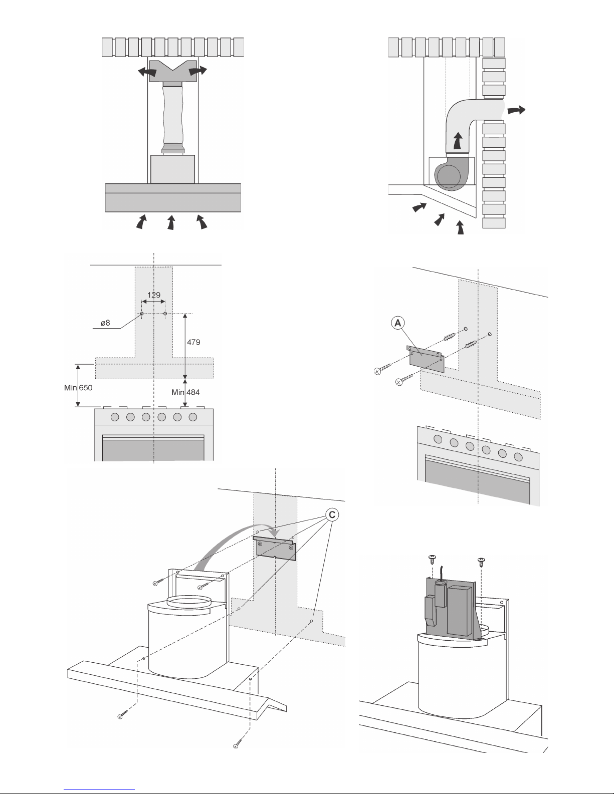
Fixing to the wall: for fixing to the wall refer to the instructions for the ducting version (see points 1, 2, 3), then continue
with the instructions below.
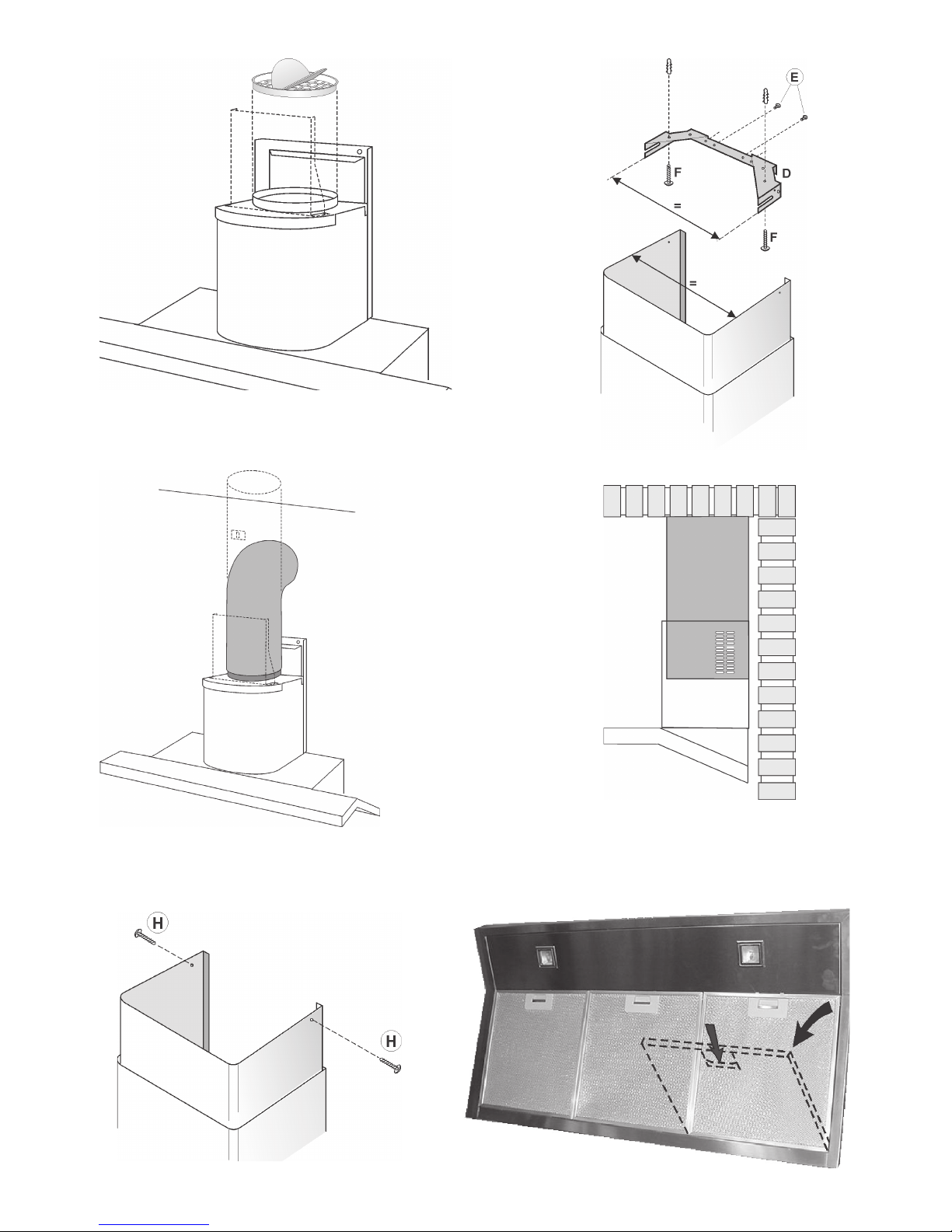
Fixing the telescopic flues: - Adjust the width of the support bracket (D) of the telescopic flue by means of the screws
(E) as shown in Fig. 8. - Then, by means of the screw anchors and screws (F) provided, fix the bracket to the ceiling in
such a way that it is positioned along the axis with your hood. - Mount the flange on the hood in correspondence to the
air outlet point (Fig. 19). - Take the air baffle and fit a flexible pipe to it (125 mm diameter) locking it with a metal hose
clamp (pipe and clamps are not provided). Fit the air baffle to the upper flue (Fig. 20) with 4 screws.
- Connect the flexible pipe to the flange on the air vent (Fig. 21). - Plug in the hood. - Insert the extension flues setting
them on the hood; extend the upper flue to the ceiling and secure with the 2 screws H (Fig. 11).
OPERATION
Depending on the model, the unit is equipped with the following controls:
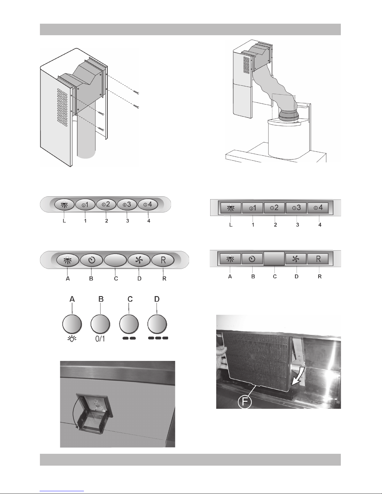
Controls shown in Fig. 22/23:
Key L: light switch. Key A : B = Motor ON/OFF switch - Speed I
Key 2: B = Motor ON/OFF switch - Speed I
Key 3: B = Motor ON/OFF switch - Speed I
Key 4: B = Motor ON/OFF switch - Speed I
Filter alarm: after about 30 hours of operation, with the motor off, the speed keys (keys 1, 2, 3 and 4) flash for 30
seconds to indicate the anti-grease filters need cleaning. After cleaning the anti-grease filters (and/or replacing the
charcoal filters), restart the hour counter (RESET) by pressing key C during filter alarm display.
Timer 5'; the timer can be started (switch-off delayed by 5 minutes) by pressing one of the speed keys for 2 seconds
(key 1, 2, 3 or 4) when the motor is running; the selected speed key starts flashing.
Controls shown in Fig. 24/25:
Button A = turns the lights on/off.
Button B = turns the TIMER on/off: press once to turn the timer on, therefore, after 5 minutes, the motor cuts out (at the
same time the selected speed blinks on the display); the timer remains on if the motor speed is changed.
Display C = - indicates the selected motor speed (from 1 to 4); - indicates Timer On when the number blinks; - indicates
Filter Alarm when the central segments is on or blinking.
Button D = makes the motor work (at the last speed selected); pushing the button again, the speeds of the motor are
sequentially selected from 1 to 4; keeping this button pressed for about 2 seconds shuts down the motor.
Button R = resets the grease filters or charcoal filters; when the filter alarm appears (i.e. when the central segment on
the display goes on), the grease filters must be cleaned (30 hours of operation); when the central segment starts blinking,
the grease filters must be cleaned and the charcoal filters replaced (120 hours of operation). Obviously, if the hood is
not a filtering model and does not have a charcoal filter , clean the grease filters both when the central segment goes
on and when it starts blinking. The filter alarm can be seen when the motor is off and for about 30 seconds. To reset the
hour counter, keep the button pressed for 2 seconds while the alarm can be seen.
Controls shown in Fig. 26:
Button A: light switch.
Button B: first speed motor ON/OFF switch.
Button C: second speed switch.
Button D: third speed switch.
Grease filters: pay special attention to the grease filters, that must be cleaned at regular intervals.
Wash the grease filter/s with neutral detergent.
Filter cleaning frequency:
If the model purchased by you has the controls represented in Fig. 22 and 23 : the grease filters must be cleaned
about every 30 hours of operation (when, with the motor off, the 4 speed keys flash). Once the clean filters have been
remounted, keep one of the 4 keys pressed for 2 seconds (during flashing) to start the hour count again.
If the model purchased by you has the controls represented in Fig. 24 and 25 : the grease filters must be cleaned
about every 30 hours of operation (when, with the motor off, the centre segment comes on or flashes on the display
screen). Once the clean filters have been fitted back on, keep the key R (Reset) pressed for 2 seconds to start the
count again.
If the model purchased by you has the controls represented in Fig. 26: the grease filter/s require particular care and
must periodically be cleaned in relation to use 2 .
Removing the grease filter/s : refer to Fig.12, Fig.13 or Fig.14 depending on the model purchased.
Fig. 12: Remove the grease filters by pushing the catch towards the rear of the hood and turning the filters outwards.
Fig. 13: grip the knob and push it towards the opposite side of the filter and turn the filter outwards (Fig. turn the filter
outwards.
Fig. 14: Turn the glass panel by gripping it from the front part of the hood. Remove the grease filters by pushing the
catch towards the rear of the hood and turning the filters outwards.
Charcoal filters: If the hood is used in the filtering version, the charcoal filter will periodically have to be
replaced in relation to use.

If the model purchased by you has the controls represented in Fig.22, Fig.23 and Fig.26 : Replace the charcoal filters
once every 6 months or at a different frequency depending on how often they are used.
If the model purchased by you has the controls represented in Fig. 24 and 25 : the hood indicates when the charcoal
filter has to be changed, meaning after about 120 hours of operation. The centre segment flashes on the display
screen (with motor off). Once the charcoal filter has been replaced, keep the R (Reset) key pressed for 2 seconds
to start the count again.
Removing the charcoal filter: refer to Fig.12, Fig.13 or Fig.14 depending on the model purchased.
Fig. 12: remove the grease filters by pushing the catch towards the rear of the hood and turning the filters outwards.
Then remove the charcoal filter (Fig. 15): push the catch towards the inside and turn the filter so that the 2 filter clips
slip out of their seats.
Fig. 13: grip the knob and push it towards the opposite side of the filter and turn the filter outwards; turn the filter
outwards. Dissasemble the charcoal filter: push the clip (F) inwards and turn the filter outwards (Fig. 27) removing the
2 flaps from their housing (Fig. 16).
Fig. 14: Turn the glass panel by gripping it from the front part of the hood. Remove the grease filter by pushing the
catch towards the rear of the hood and turning the filter outwards. Dissasemble the charcoal filter as follows,
depending on the models:
To remove the rectangular charcoal filter (Fig. 15): push clip inwards and turn the filter removing the 2 flaps from their
housing.
To remove the panel charcoal filter (Fig. 18): remove the metal filter clips (M) and remove the filter.
Replacing the lamps : open the halogen lamp door by pressing on one side (where it says PUSH) and release
(Fig. 28). Replace with lamps of the same type. WARNING: do not touch the new lamp with bare hands.
IMPORTANT Only for models with perimeter extraction (example the model shown in Fig.14 with opening panel):
in the event of strong vapour concentrations, condensation could form in the lower part of the hood; this is not a
defect, nor does it affect normal operation of the hood.

12
34
56

7
8
9
10
11 12

16
1413
15
17 18
19

04307891 - K9998-om
25
21
24
23
20
28
26
22
27
Table of contents
Other Smeg Ventilation Hood manuals
Popular Ventilation Hood manuals by other brands

NEFF
NEFF D39L49S0 instruction manual

Vallox
Vallox X-Line KTX manual

Convotherm
Convotherm ConvoVent 4+ Operating and installtion instructions

Monogram
Monogram ZV750 owner's manual

Wind Crest
Wind Crest WST300SBG Use, care and installation guide

Spagna Vetro
Spagna Vetro SV400 SERIES Installation guide and user's manual