Smeg KSEIV97X User manual

LibrettoIstruzioni
InstructionManual
Manueld’Instructions
Bedienungsanleitung
Gebruiksaanwijzing
ManualdeInstrucciones
NL 42
DE 32
FR 22
GB 12
IT 2
ES 52
KSEIV97X

12GB
CONTENTS
Dear Customer,
If you follow the recommendations
contained in this Instruction Manual,
your appliance will give you constant
high performance and will remain
efficient for many years to come.
RECOMMENDATIONSANDSUGGESTIONS 13
CHARACTERISTICS 14
INSTALLATION 16
USE 19
MAINTENANCE 20

13GB
RECOMMENDATIONS AND SUGGESTIONS
INSTALLATION
• The manufacturer will not be held liable for any damages resulting
from incorrect or improper installation.
• The minimum safety distance between the cooker top and the
extractor hood is 650 mm.
• Check that the mains voltage corresponds to that indicated on the
rating plate fixed to the inside of the hood.
• For Class I appliances, check that the domestic power supply
guarantees adequate earthing.
Connect the extractor to the exhaust flue through a pipe of
minimum diameter 120 mm. The route of the flue must be as short
as possible.
• Do not connect the extractor hood to exhaust ducts carrying
combustion fumes (boilers, fireplaces, etc.).
• Iftheextractorisused in conjunctionwith non-electrical appliances
(e.g. gas burning appliances), a sufficient degree of aeration must
be guaranteed in the room in order to prevent the backflow of
exhaust gas. The kitchen must have an opening communicating
directly with the open air in order to guarantee the entry of clean
air.
USE
• The extractor hood has been designed exclusively for domestic
use to eliminate kitchen smells.
• Never use the hood for purposes other than for which it has ben
designed.
• Never leave high naked flames under the hood when it is in
operation.
• Adjust the flame intensity to direct it onto the bottom of the pan
only, making sure that it does not engulf the sides.
• Deep fat fryers must be continuously monitored during use:
overheated oil can burst into flames.
• The hood should not be used by children or persons not instructed
in its correct use.
MAINTENANCE
• Switch off or unplug the appliance from the mains supply before
carrying out any maintenance work.
• Clean and/or replace the Filters after the specified time period.
• Clean the hood using a damp cloth and a neutral liquid detergent.
650 mm min.

14GB
CHARACTERISTICS
Dimensions
650 min.
680
470
290
898
68
565
90
132
433
150
350
740
740
940

15GB
7.1a
7.1
22
23
12h
7.1b
2
2.1
2.2
8b 8a
12c
11
21
12g
1
12f
25
24
12e
12c
12c
14.1
15
10
14
Components
Ref. Q.ty Product Components
11 Hood Body, complete with: Controls, Light,
Blower, Filters
21 Telescopic Chimney comprising:
2.1 1 Upper Section
2.2 1 Lower Section
7.1 1 Telescopic frame complete with extractor,
consisting of:
7.1a 1 Upper frame
7.1b 1 Lower frame
8a 1 Right Air Outlet Grill
8b 1 Left Air Outlet Grill
10 1 Damper
14 1 Hood BodyAir Outlet Extension Piece
consisting of two Half Shells
14.1 1 Air Outlet Connection Extension
15 1 Air Outlet Connection
24 1 Junction box
25 2 Pipe clamps
Ref. Q.ty Installation Components
11 4 Wall Plugs ø 10
12c 6 Screws 2,9 x 6,5
12e 2 Screws 2,9 x 9,5
12f 4 Screws M6 x 10
12g 4 Screws M6 x 80
12h 4 Screws 5,2 x 70
21 1 Drilling template
22 4 6.4 mm int. dia washers
23 4 M6 nuts
Q.ty Documentation
1 Instruction Manual

16GB
INSTALLATION
Drilling the Ceiling/shelf and fixing the frame
DRILLING THE CEILING/SHELF
• Use a plumb line to mark the centre of the hob on the ceiling/support shelf.
• Place the drilling template 21 provided on the ceiling/support shelf, making sure that the template
is in the correct position by lining up the axes of the template with those of the hob.
• Mark the centres of the holes in the template.
• Drill the holes at the points marked:
• For concrete ceilings, drill for plugs appropriate to the screw size.
• For hollow brick ceilings with wall thickness of 20 mm: drill ø 10 mm.
• For wooden beam ceilings, drill according to the wood screws used.
• For wooden shelf, drill ø 7 mm.
• For the power supply cable feed, drill ø 10 mm.
• For the air outlet (Ducted Version), drill according to the diameter of the external air exhaust
duct connection.
FIXING THE FRAME
Before fixing, separate the Upper Section 2.1 and
the Lower Section 2.2 from the Frame by
unscrewing the screws 12c, then separate the two
sections of the frame by unscrewing the 8 side
screws to obtain the Upper frame and Lower fra-
me.

17GB
14
15
14.1
10
ø 150
25
Upper frame
• Align the power supply cable feed hole
• Fix the upper frame to the ceiling or shelf using:
• For concrete ceilings, use the appropriate plugs for the screw size (not provided).
• For hollow brick ceilings of wall thickness of approximately 20 mm: use 4 plugs 11 and 4
screws 12h (5,2 x 70), provided.
• For wooden beam ceilings, use 4 wood screws (not provided).
• For wooden shelf, use 4 screws 12g (M6 x 80) with washers 22 and nuts 23, provided.
Lower frame
• Fix the lower frame using the 8 previously removed screws, adjusting the length according to the
installation height (hood body lower fixing surface must be at least 710 mm from the hob).
• For the recirculation version, turn the frame in the direction chosen for the recirculated air outlet.
• The frame mountings must be secure to withstand the weight of the hood and any stresses caused
by the occasional side thrust applied to the device. On completion, check that the base is stable,
even if the frame is subjected to bending.
• In all cases where the ceiling is not strong enough at the suspension point, the installer must
provide strengthening using suitable plates and backing pieces anchored to the structurally sound
parts.
Connections
DUCTED VERSION AIR EXHAUST SYSTEM
In order to install the ducted version, connect the hood to the chimney using either a flexible or rigid
pipe ø 150 mm, the choice of which is left to the installer.
• Push fit Damper 10 onto the air outlet.
• Fix the pipe using the pipe clamps 25 provided.
• Remove any activated charcoal filters.
RECIRCULATION VERSION AIR OUTLET
• Assemble the two halves of the hood body
extension piece 14.
• Push fit the assembled hood body extension
piece 14 onto the air outlet.
• Push fit connection 15 onto the hood body
extension piece 14.
• Insert the connection extension pieces laterally
14.1 in connection 15.

18GB
12f
8b 8a
12c
12c
24
12e
Cmd
12c
Lux
Flue assembly - Mounting the hood body
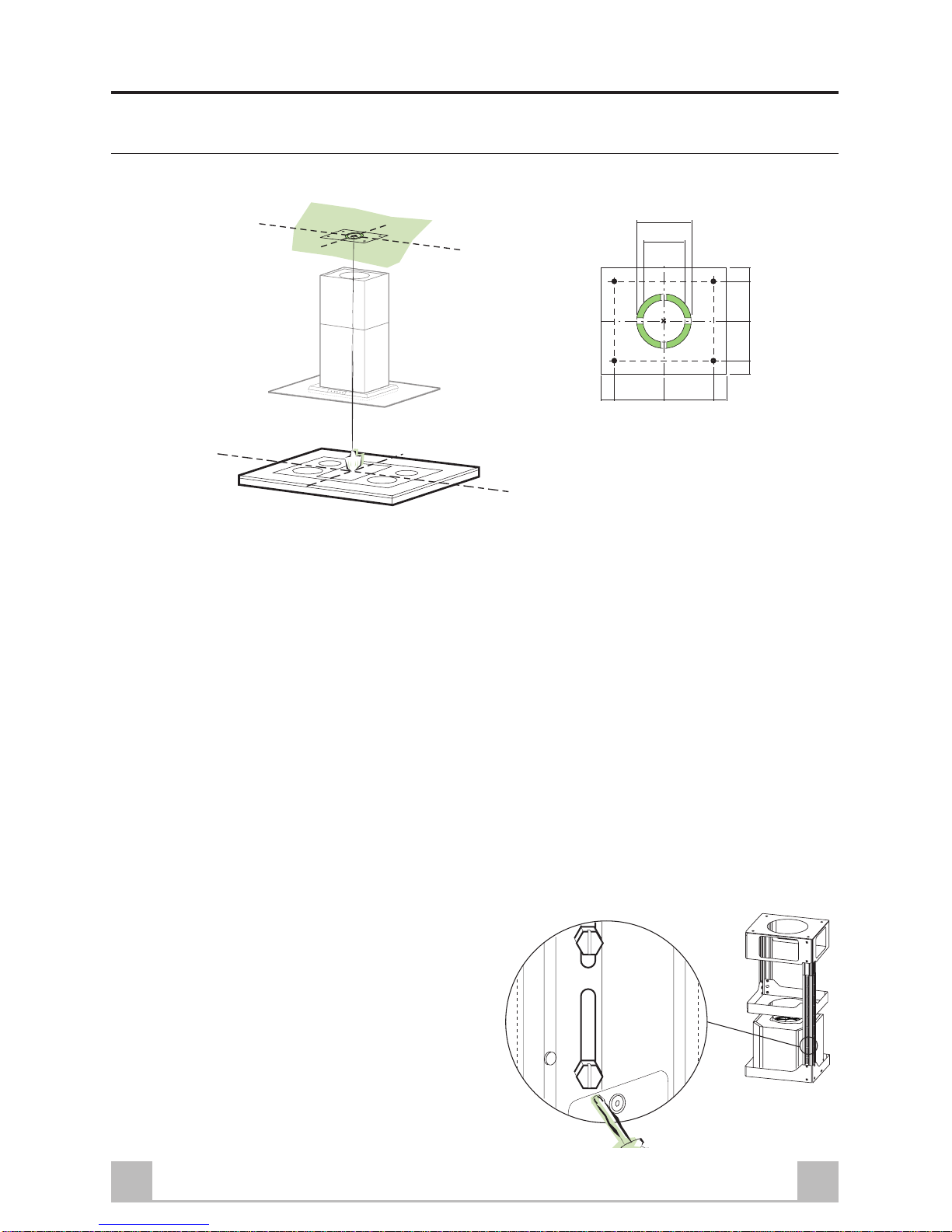
• Position the upper chimney section and fix the
upper part to the frame using the 2 screws 12c
(2,9 x 6,5) provided.
• Similarly, position the lower chimney section
and fix the lower part to the frame using the 2
screws 12c (2,9 x 6,5) provided.
Recirculation version
• Makesure that the outlet of the extension pieces
14.1 is horizontally and vertically aligned with
the chimney outlets.
• Ifthis is not the case, remove the lower chimney
section and adjust the position by either
reversing the connection extension pieces 14.1
or by cutting the hood body extension 14 along
one of the thinner section channels denoting the
pre-fixed lengths, then reassemble as described
previously.
• Fit the directional grids 8a-8b in their housings
making sure that the directional symbols are
towards the top. Also make sure that they are
correctly inserted in the connection extension
pieces 14.1.
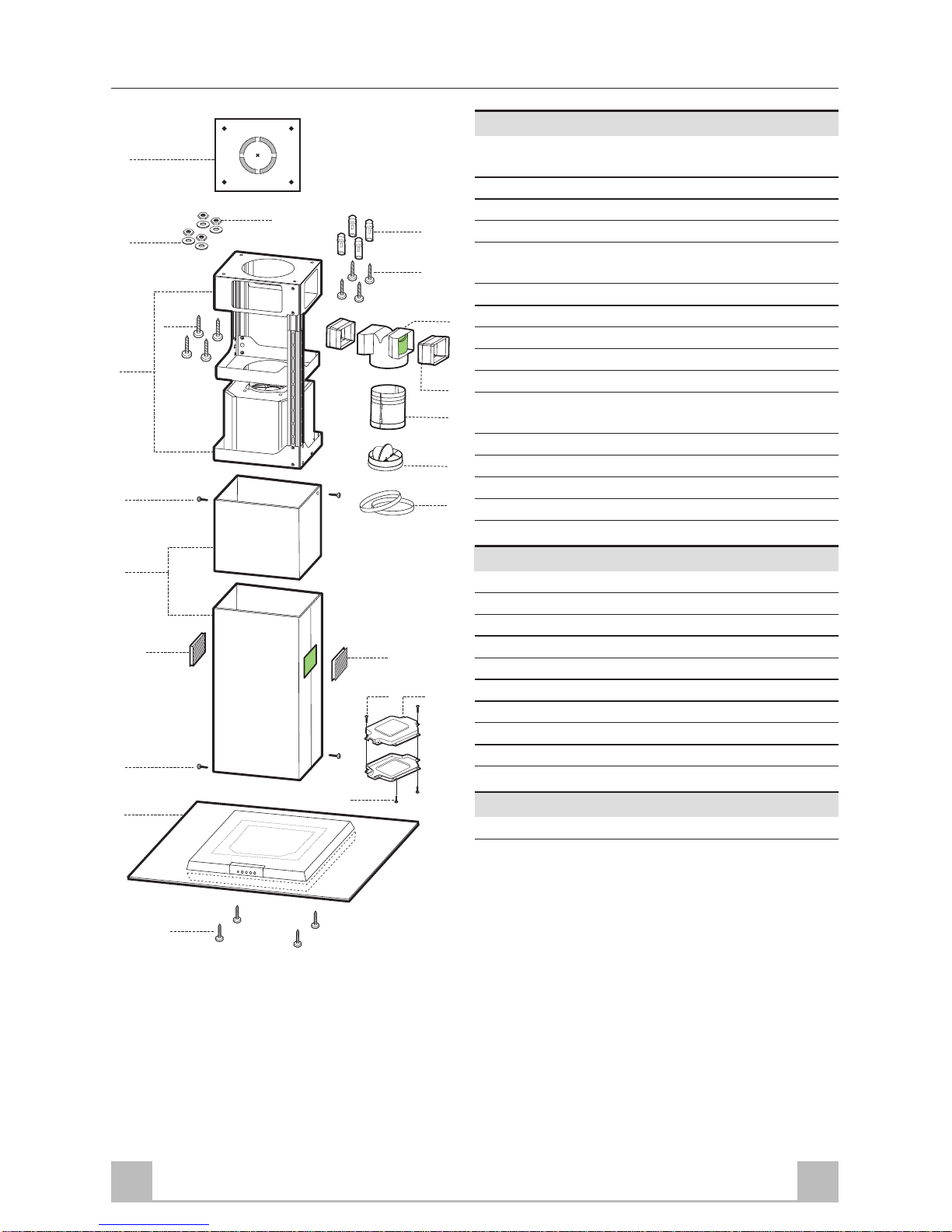
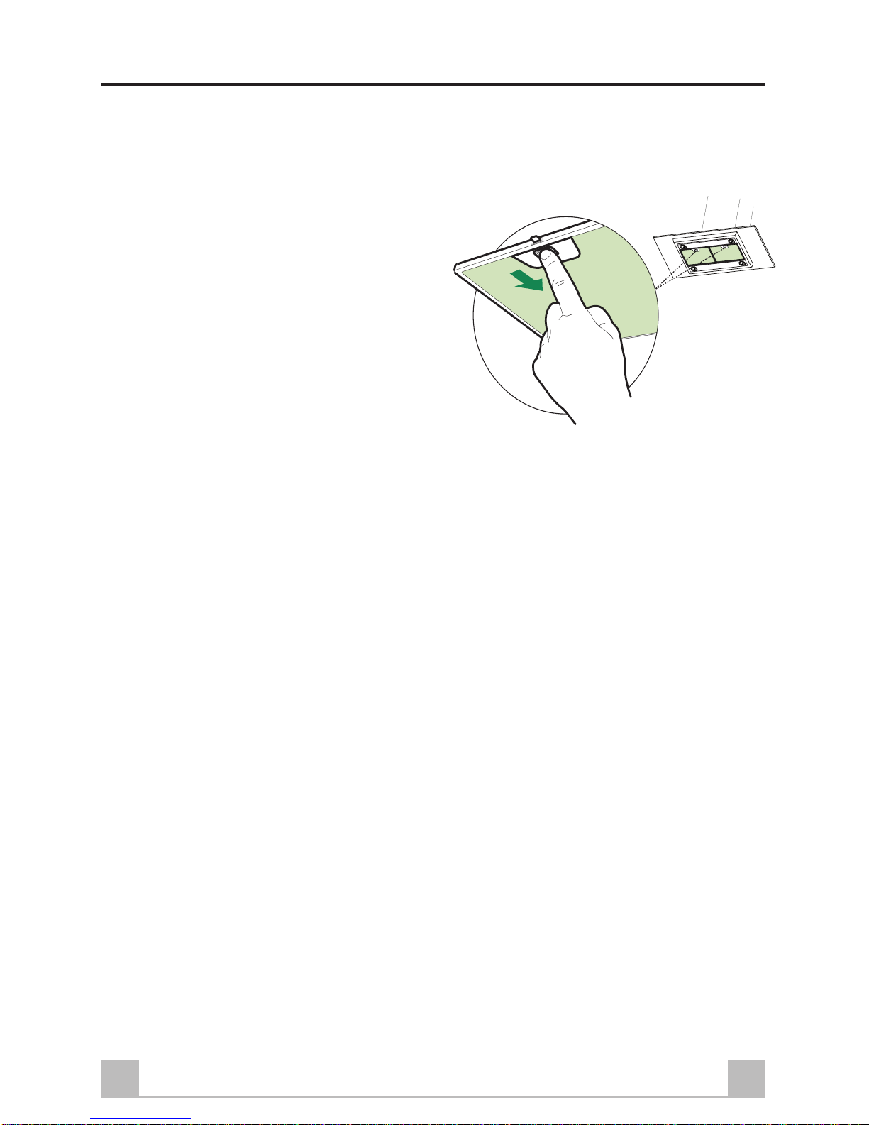
Before fixing the hood body to the frame:
• Remove the grease filters from the hood body.
• Remove any activated charcoal filters.
• From below, use the 4 screws 12f (M6 x 10)
provided to fix the hood body to the frame.
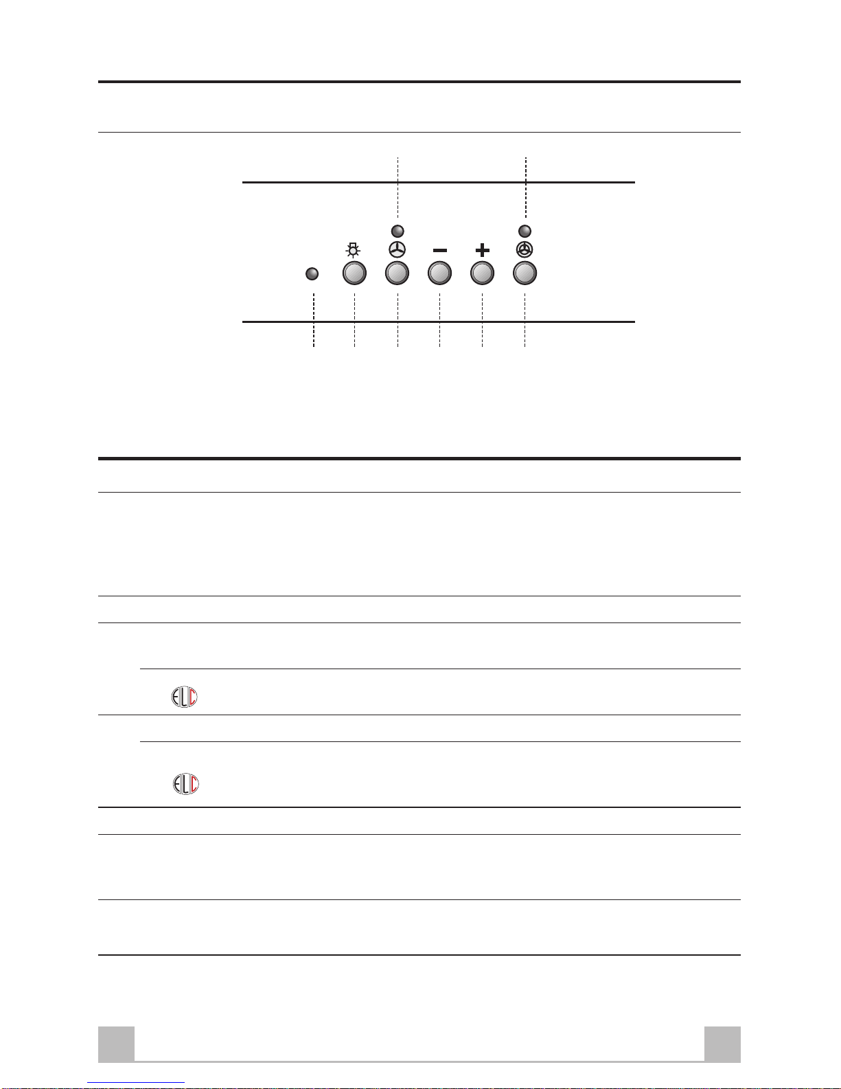
ELECTRICAL CONNECTION
• Connect the hood to the mains through a two-
pole switch having a contact gap of at least 3
mm.
• Connect the control connector Cmd.
• Connect the lights connector Lux.
• Place the connector in the junction box 24 and
close it using the 2 screws 12e (2,9 x 9,5)
provided.
• Fix the junction box to the hood body using the
2 screws 12c (2,9 x 6,5) provided.
• For the recirculation version, fit the activated
carbon odour filter.
• Replace the grease filters.

19GB
L
RV1 V2 V3
M
S1 S2
USE
Controlpanel
LLight Switches the lighting system on and off.
S1 Led Motor running led.
It flashes once after 100 working hours of the hood to indicate that the grease
filters need washing.
It flashes twice after 200 working hours to indicate that the grease filters need
washing and that the anti-odour charcoal filters, if any, need changing.
S2 Led Intensive speed led.
MMotor Switches the extractor motor on and off at low speed. Used to provide a
contin-uos and silent air change in the presence of light cooking vapours.
When the Hood is in ELC (Electronic Comfort) mode, the button will not only
turn the Ducting motor on, but will also disable this function.
V1 Speed Reduces the operating speed.
When the button is pressed with the Motor off, ELC (Electronic Comfort)
mode will be enabled again, giving a continuous, low noise flow of air. Press
the button and hold it until Led S1 flashes slowly.
V2 Speed Increases the operating speed.
V3 Intensive Maximum speed, used for eliminating the highest cooking vapour emission.
Speed Switches off automatically after 10 minutes operation. Can also be switched
off manually by pressing the button.
RReceiverfor Optional Remote Control.
Remote Control

20GB
MAINTENANCE
Greasefilters
CLEANING METAL SELF- SUPPORTING GREASE FILTERS
Alarm signal reset
• Switch off the lights and extractor motor.
• Press button V2 for at least 3 seconds, until the
leds start to flash.
Cleaning the filters
• The filters must be cleaned when led S1 flashes
or at least every 2 months of operation, or more
frequently for particularly heavy usage.
• Remove the filters one at a time by pushing
them towards the back of the group and pulling
down at the same time.
• Wash the filters, taking care not to bend them.
Allow them to dry before refitting.
• When refitting the filters, make sure that the
handle is visible on the outside.

21GB
Activatedcharcoalfilter(Recirculationversion)
REPLACING THE ACTIVATED CHARCOAL FILTER
• The filter is not washable and cannot be
regenerated. It must be replaced when led S1
flashes twice or at least every 4 months. The
alarmsignal willonly lightup whenthe extractor
motor is switched on.
Alarm signal reset
• Switch off the lights and extractor motor.
• Press button V2 for at least 3 seconds, until the
leds start to flash.
Replacing the Filter
• Remove the metal grease filters.
• Remove the saturated activated carbon filter by
releasingthe fixing hooks.
• Fit the new filter by hooking it into its seating
Replace the metal grease filters.
Alarm signal activation
• On the recirulcation version extractor hood, the
filter saturation alarm is activated during
installation or at a later date.
• Switch off the lights and extractor motor.
• Press button V2 for at least 10 seconds, until
the leds start to flash:
• 2 flashes of the activated carbon odour filter
saturation alarm led = filter ACTIVATED
• 1 flash of the activated carbon odour filter
saturation alarm led = filter DEACTIVATED
Lighting
LIGHT REPLACEMENT
20 W halogen light.
• Removethe2 screwsfixing theLightingsupport,
and pull it out of from the Hood.
• Extract the lamp from the Support.
• Replace with another of the same type, making
sure that the two pins are properly inserted in
the lamp holder socket holes.
• Replace the Support and fix it in place with the
two Screws removed as above.

Quest’apparecchio è conforme alla norma europea sulla bassa tensione C.E.E. 73/23 relativa alla sicurezza elettrica e alle norme
europee: C.E.E. 89/336 relativa alla compatibilità elettromagnetica e C.E.E. 93/68 relativa alla marcatura CE.
This appliance conforms to European Low Voltage Directive 73/23/CEE governing electrical safety, European Directive 89/
336/CEE on Electromagnetic Compatibility and Directive 93/68/CEE regarding CE Marking.
Cet appareil est conforme à la norme européenne en matière de basse tension C.E.E. 73/23 de sécurité électrique ainsi qu’aux
normes européennes : C.E.E. 89/336 en matière de compatibilité électromagnétique et C.E.E. 93/68 en matière de label CE.
Dieses Gerät entspricht folgenden EG-Richtlinien: Niederspannungsrichtlinie EWG 73/23 hinsichtlich elektrischer Sicherheit,
Richtlinie Elektromagnetische Verträglichkeit EWG 89/336 und Richtlinie EWG 93/68 hinsichtlich der CE-Kennzeichnung.
Dit apparaat voldoet aan de Europese laagspanningsnorm 73/23/EEG inzake de elektrische veiligheid en de Europese normen:
89/336/EEG inzake de elektromagnetische compatibiliteit en 93/68/EEG inzake de CE-markering.
Este aparato es conforme con la normativa europea sobre baja tensión C.E.E. 73/23 correspondiente a la seguridad eléctrica y
a las normativas europeas: C.E.E. 89/336 sobre la compatibilidad electromagnética e C.E.E. 93/68 respeitante à marcação CE.
43600163703 -021219
Other manuals for KSEIV97X
1
Table of contents
Other Smeg Ventilation Hood manuals

Smeg
Smeg K9998 User manual

Smeg
Smeg KSED97X Technical manual

Smeg
Smeg KSEG52 Technical manual

Smeg
Smeg KSEM90X Technical manual

Smeg
Smeg Universale KSCB120XE User manual

Smeg
Smeg KSED65X Technical manual

Smeg
Smeg KSEI62 User manual

Smeg
Smeg KSEV97X Quick start guide

Smeg
Smeg CK2000LED User manual

Smeg
Smeg KSET66 User manual