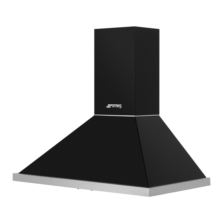
Smeg K24SLM90 User manual

INSTRUCTIONS FOR INSTALLATION AND USE
MONTAGE- UND GEBRAUCHSANWEISUNG
INSTRUCTIONS POUR L'INSTALLATION ET L’UTILISATION
ISTRUZIONI PER L'INSTALLAZIONE E L’USO
INSTRUCCIONES PARA INSTALACIÓN Y USO
INSTRUÇÕES DE INSTALAÇÃO Y UTILIZAÇÃO
AANWIJZING VOOR GEBRUIK EN INSTALLATIE


ENGLISH
DESCRIPTION
This appliance is equipped with a completely automatic system (Advanced Sensor Control) capable
to manage all the functions of your hood. Thanks to the ASC, the air in the kitchen is costantly clean
and odour free without any manual intervention. The advanced sensor catches all sort of vapours,
smokes and odours caused by the cooking process. The ASC also captures an abnormal presence of
GAS.
The hood may be installed in the filtering or the ducting version.
Filtering version (Fig. 1): The hood aspirates the kitchen air saturated with fumes and odours, purifies it through
the grease filters and charcoal filters and returns clean air into the room. For constant efficiency, the charcoal
filters must be replaced periodically. The charcoal filters are not supplied.
Ducting version (Fig. 2): The hood aspirates the kitchen air saturated with fumes and odours, passes it through
the grease filters and expels it to the outside through an outlet pipe. With this version the charcoal filters are
not required.
Decide from the outset on the type of installation (filtering or ducting). For greater efficiency, we recommend you
install the hood in the ducting version (if possible).
INSTALLATION
To facilitate installation, before starting remove the grease filters: press inward on the clamp at the handle
and pull the filter downward (Fig. 3).
Wall fitting (Fig. 4): making use of the appropriate drilling jig, apply the supplied blocks into the wall, and
remember the distance between the hood and the cooktop must be at least 65 cm. Insert two of the supplied
screws so that the apparatus can be hooked onto these ones by means of the holes provided on the appliance
(A). Once the apparatus is hooked, fix it definitively to the wall using the two other screws and the holes made
at its bottom (B). To avoid damage make exclusive use of the holes already prepared on the hood.
Securing the telescopic flue: Basic installation requirements: – Set the electrical power supply within the
space covered by the decorative flue. – If your unit is installed in an Exhaust hood, prepare the air exhaust hole.
Place bracket (W) 50 mm from the ceiling and position this on the vertical of your hood, with the aid of the notches
on the centre of the bracket (Fig. 5); using a pen, mark the 2 holes on the wall and then make the holes and
fit the screw anchors provided and proceed to secure the bracket using the 2 screws (provided).
Exhaust hoods: connect the disposal duct to the air evacuation pipe of the hood; use a flexible pipe and lock
it to the air evacuation pipe of the hood with a metal hose clamp (pipe and clamp are not provided). Make all
power connections to the hood by means of the power cable. Take 2 assembled flues and place these on the
upper surface of the hood. Raise the upper flue as far as the ceiling and secure it to the bracket using the 2
screws (Fig. 6).
Filtering hood: make all power connections to the hood using the power cable. Fasten the air baffle to the lower
flue as shown in Figure 7, using the 2 screws. Take 2 assembled flues and place these on the upper surface
of the hood. Raise the upper flue as far as the ceiling and secure it to the bracket using the 2 screws (Fig.
6).
Also remember that charcoal filters must be used in the case of the filtering version; check to see whether such
filters are already fitted; if necessary, proceed to fit as follows, depending on the model type purchased:
- if the hood features round charcoal filters (Fig. 8), fit the charcoal filter by turning anti-clockwise.
OPERATION
Depending on the model, the unit is equipped with the following controls:
Controls shown in Fig. 9:
P1- Lights ON/OFF; filter alarm RESET: if held pressed down for about 2 seconds when the filter alarm is
active, the hour counter is reset. Filter alarm: after 30 hours the light button LED comes on and stays on
for 30 seconds (Grease filters alarm); after 120 hours it is activated for 30 seconds but with the LED flashing
(Charcoal filters alarm). The RESET is highlighted ONLY when the motor is OFF, both in automatic and manual
mode.
Automatic function:
To activate the automatic function press P2, highlighted by the corresponding LED coming on; the flashing LED
indicates that the sensor is waiting for data.
To set the sensitivity: in manual mode and with the motor off press P2 and P3 simultaneously; the sensitivity already
set with the P3 or P4 or P5 LEDs is highlighted. To modify it, press P3 or P4 or P5 (MIN, MED, MAX), and again press
P2 to store it. At this point, the desired sensitivity has been stored; press P2 again to deactivate the automatic mode.
Manual function:
When the LED P2 is off, you are in manual mode. Press P3 when in manual mode to turn on the motor in 1st speed
with the relevant LED on. Holding it down for 2 seconds, the motor is turned off. Press P4 to go to 2nd speed with
the relevant LED on and P5 to go to 3rd speed with the relevant LED on.

Controls shown in Fig. 10:
P1) Lights OFF: If pressed, lights go off.
P2) Lights ON: If pressed, lights go on.
P3) OFF/- Motor: Speed drop until minimum speed is reached.
If pressed for 2", motor switches off.
If pressed for 2" with FILTER RESET on HOUR count reset.
P4) ON/+ Motor: Starts motor and increases motor speed until top speed is reached.
P5) ON/OFF: Switches Sensor off and on( AUTOMATIC or MANUAL mode).In Automatic mode, LED L2 is on and L1
shows operating speed In Manual mode, LED L2 is off.
L1) 4 LEDs 4 GREEN LEDs. Indicate set speed.
L2) LED GREEN indicates AUTOMATIC mode. OFF indicates MANUAL mode. RED indicates Filter Alarm.
FILTER ALARM: shown with Motor Off for 30": After 30h the LED L2 becomes steady RED (Grease filters alarm). After
120h LED L2 becomes flashing RED (Charcoal Filters alarm). Reset by means of P3.
SENSITIVITY: In manual mode, by pressing P5 and P4 together, sensitivity mode is entered. The set sensitivity is
indicated by the 4 green LEDs. By means of buttons P3(-) and P4(+) the desired sensitivity is set (fig. 10/A).
By pressing P5 the sensitivity can be stored, with return to manual mode.
Controls shown in Fig. 11:
A) Turns the LIGHTS on and off.
B) Turns the LUMINOUS STRIP on and off.
C) Reduces the motor speed until reaching zero. If pressed for 2" the motor is turned off.
D) Activates the motor (calling the last speed used) and increases the speed until reaching maximum..
E) FILTER ALARM/TIMER RESET: when pressing the key during display of the filter alarm (motor off) it resets the hour
counter.Whenpressingthekeywhenthemotorisrunning,theTIMERisactivatedandthehoodwillautomaticallybeswitched
off after 5 minutes.
L1) The 4 green LEDs indicate the running speed.
L2) When the LED is red (motor off) it indicates the FILTER ALARM. When the LED is green (flashing) it indicates that
the TIMER has been activated with the key E.
FILTERALARM:
After 30h of operation, the LED L2 turns RED. It indicates that the grease filters need to be cleaned.
After 120h of operation, the LED L2 turns RED and flashes; It indicates that the grease filters need to be cleaned and
the charcoal filters replaced.
After cleaning the grease filters (and/or replacing the charcoal filters), restart the hour counter (RESET) by pressing the
key E during display of the filter alarm.
Grease filters: special attention must be given to the grease filters which must be periodically cleaned, whenever
the grease filter alarm trips. For instructions of the filter Alarm, refer to the Controls paragraph. Remove the filters as
shown in para. 1 and wash with neutral detergent.
Charcoal filters: if the filtering version appliance is used, the charcoal filters will have to be periodically replaced
when the charcoal filter alarm trips. For instructions on the filter Alarm, refer to the Controls paragraph.
Lighting:
- If the halogen lamps shown in Fig. 12 need changing, slacken the ring nut in an anticlockwise direction and
remove the bulb itself. Replace with the same type of lamp. CAUTION: Do not handle glass bulb with bare hands.
- To change the halogen lamps shown in Fig. 13 open the cover levering from the proper slots. Replace with the
same type of lamp. CAUTION: Do not handle glass bulb with bare hands.
DEUTSCH
BESCHREIBUNG
Diese Abzugshaube ist mit einem vollkommen automatischen System (Advanced Sensor Control) zur
Verwaltung aller vorhandenen Funktionen ausgestattet. Das Raumklima in der Küche bleibt konstant angenehm
und frisch, ohne manuelle Steuerung! Die sensiblen Sensoren spüren jede Art von Dunst, Wrasen, Gerüchen
sowie GAS auf und passen die notwendige Gebläseleistung automatisch an.
Die Haube kann als Umluftversion oder als Abluftversion installiert werden.
Umluftversion (Abb. 1): die Haube saugt die mit Rauch und Gerüchen gesättigte Luft an und reinigt sie durch
die Fett- und den Kohlefilter. Danach wird die saubere Luft wieder in den Raum geleitet. Um die gleichmäßige
Wirksamkeit der Kohlefilter zu erhalten, müssen sie regelmäßig ausgetauscht werden. Die Kohlefilter werden nicht
mitgeliefert.
Abluftversion (Abb. 2): die Haube saugt die mit Rauch und Gerüchen gesättigte Luft an, leitet sie durch die Fettfilter
und gibt sie über ein Abführungsrohr nach außen ab. Diese Version benötigt keinen Kohlefilter.
Entscheiden Sie sich von Anfang an für einen Installationstyp (Umluft oder Abluft). Um eine größere Wirkung
zu erzielen, empfehlen wir die Installation einer Haube in Abluftversion (falls möglich).

MONTAGE DES GERÄTS
Vor den Montageoperationen muß/müssen zur leichteren Handhabung des Geräts die Fettfilter entfernt werden:
Den Festhalter in der Nähe des Griffs nach innen drücken und den Filter nach unten ziehen (Abb. 3).
Befestigung an der Wand (Abb. 4): Benutzen Sie die Bohrschablone, um die Dübel in der Wand anzubringen,
wobei der Abstand zwischen der Haube und dem Kochfeld mindestens 65 cm betragen muß. Nun kann das Gerät
mit den Schlüssellochöffnungen in der Geräterückwand in die Schrauben eingehängt werden (A). Zusätzlich wird
das Gerät durch die Sicherungslöcher fest mit der Wand verschraubt (B). Um das Gerät nicht zu beschädigen,
dürfen nur die vom Hersteller vorgesehenen Bohrungen benutzt werden.
Befestigung der Teleskoprohre: Mindestanforderungen für die Montage: – Stromversorgungsanschluß innerhalb
der Außenabmessungen des Teleksoprohres vornehmen. – Wenn Ihr Gerät als Abluftversion installiert wird, ist ein
Loch zur Abführung der Luft vorzusehen.
Positionieren Sie die Halterung (W) 50 mm von der Decke entfernt, vertikal oberhalb der Haube unter Zuhilfenahme
der Schlitze in der Mitte der Halterung (Abb. 5). Markieren Sie mit einem Filzstift die beiden Bohrlöcher an der
Wand. Führen Sie die Bohrungen aus und stecken Sie die mitgelieferten Dübel in die Bohrlöcher. Befestigen Sie
die Halterung mit den beiden mitgelieferten Schrauben.
Abluftversion: Das Luftabführungsrohr an die Austrittsöffnung der Haube anschließen; dazu einen Schlauch
verwenden und ihn an der Luftaustrittsöffnung der Haube mit einer Metallschelle befestigen (Schlauch und Schelle
werden nicht mitgeliefert). Schließen Sie die Haube mittels Stromkabel an die Stromversorgung an. Legen Sie die
beiden vormontierten Rohre auf den vorderen Teil der Haube. Heben Sie das obere Rohr bis zur Decke an und
bestigen Sie es mittels 2 Schrauben an der Halterung (Abb. 6).
Umluftversion: Schließen Sie die Haube mittels Stromkabel an die Stromversorgung an. Befestigen Sie das
Ableitblech an dem unteren Rohr wie in Abbildung 7 gezeigt. Benutzen Sie hierzu 2 Schrauben. Legen Sie die
beiden vormontierten Rohre auf den vorderen Teil der Haube. Heben Sie das obere Rohr bis zur Decke an und
bestigen Sie es mittels 2 Schrauben an der Halterung (Abb. 6).
Beachten Sie, dass bei der Umluftversion der Gebrauch von Kohlefiltern erforderlich ist; uberprüfen Sie, ob die
Filter bereits installiert sind; falls erforderlich, montieren Sie diese wie nachstehend beschrieben ist, entsprechend
dem von Ihnen erworbenen Modell:
- wenn die Haube mit runden Kohlefiltern ausgestattet ist (Abb. 8), hängen Sie den Kohlefilter durch Drehen
desselben im Gegenuhrzeigersinn ein.
FUNKTIONSWEISE
Je nach Version ist das Gerät mit folgenden Bedienung ausgestattet:.
Bedienung gemäß Abb. 9:
P1- ON/OFF Lichter; RESET Filteralarm: Durch circa 2" langes Gedrückthalten, wenn der Filteralarm aktiv ist,
wird die Stundenzählung rückgestellt. Filteralarm: Nach 30h leuchtet 30" lang die Anzeigelampe der Lichttaste
auf (Fettfilter Alarm); nach 120h Stunden blinkt diese LED 30" lang (Kohlefilter Alarm). Die Rückstellung wird
NUR bei STILLSTEHENDEM Motor bei automatischer sowie manueller Betriebsart angezeigt.
Automatischer Betrieb:
Zum Einschalten des automatischen Betriebs: P2 betätigen, zur Anzeige leuchtet die zutreffende LED auf.; blinkt die
LED, bedeutet dies, daß der Sensor auf die Dateneingabe wartet.
Zum Einstellen der Empfindlichkeit: Bei manueller Betriebsart und stillstehendem Motor gleichzeitig P2 und P3
betätigen, es wird die bereits eingestellte Empfindlichkeit durch die LEDs von P3 oder P4 oder P5 angezeigt. Dann
zum Ändern P3 oder P4 oder P5 (min, Med, MAX) betätigen und zum Speichern erneut auf P2 drücken.
Jetzt ist die gewünschte Geschwindigkeit gespeichert; bei erneuter Betätigung von P2 wird die automatische
Betriebsart ausgeschaltet.
Manueller Betrieb:
Wenn die LED P2 nicht leuchtet, besteht die manuelle Betriebsart. Wird bei manueller Betriebsart P3 betätigt, wird
der Motor mit 1. Geschwindigkeit gestartet und die zutreffende LED leuchtet. Durch 2" langes Gedrückthalten wird
der Motor abgeschaltet. Durch Betätigung von P4 wird auf die 2. Geschwindigkeit geschaltet und die zutreffende
LED leuchtet; durch Betätigung von P5 wird auf die 3. Geschwindigkeit geschaltet und die zutreffende LED
leuchtet.
BedienunggemäßAbb.10:
P1) Lampen AUS : Bei Betätigung der Taste schalten sich die Lampen aus.
P2) Lampen EIN: Bei Betätigung der Taste schalten sich Lampen ein.
P3) OFF/- Motor: Vermindert die Geschwindigkeit bis zur Mindestgeschwindigkeit. Bei Betätigung für 2" schaltet sich
der Motor aus. Bei Betätigung für 2" und Aktivierung von FILTER RESET wird der Stundenzähler auf null gestellt.
P4) ON/+ Motor: Schaltet den Motor ein und erhöht die Geschwindigkeit des Motors bis zur Höchstgeschwindigkeit.
P5) ON/OFF: Aktiviert/deaktiviert den Sensor( AUTOMATISCHER oder MANUELLER Betriebsmodus). Im automatischen
Betriebsmodus ist LED L2 eingeschaltet und LED L1 zeigt die jeweils laufende Geschwindigkeit an. Im manuellen
Betriebsmodus ist LED L2 ausgeschaltet.
L1) 4 Leds: 4 GRÜNE LEDs. Zeigen die eingestellte Geschwindigkeit an.
Table of contents
Languages:
Other Smeg Ventilation Hood manuals
Popular Ventilation Hood manuals by other brands

Gorenje
Gorenje S3 IHGC963S4X manual

KOBE
KOBE ISX2136SQB-1 Installation instructions and operation manual

U.S. Products
U.S. Products ADVANTAGE-100H Information & operating instructions

Kuppersberg
Kuppersberg DUDL 4 LX Technical Passport

Framtid
Framtid HW280 manual

Thermador
Thermador HGEW 36 FS installation manual