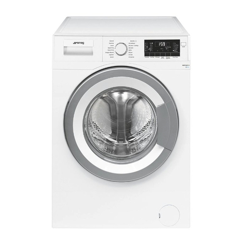
Smeg GW2045 Instruction Manual

www.labec.com.au
Laboratory Equipment Pty Ltd
email: sales@labec.com.au
Ph: 02 9560 2811 •Fax: 02 9560 6131
2014
INSTRUCTION MANUAL

GW2045
GW1060
GLASSWARE WASHER
OPERATING INSTRUCTIONS MANUAL

CAREFULLY READ THIS INSTRUCTION MANUAL
Failure to read or fully understand the instruction manual, or incorrect interpretation of the
instructions herein may cause damage to the appliance as well as being a source of
danger for the operator and lowering the performances provided by the machine to a
considerable extent.
The manufacturer declines all liability for uses differing from those listed below.
The machine must only be installed, serviced and repaired by
authorized personnel.
The warranty could become void if the machine is used in a way that
Fails to Conform to the instructions given by SMEG.
This manual is for informational purposes only. The contents of this manual and the
appliance described herein may be liable to modification without prior notice. In no case
may SMEG be held liable for any direct or accidental damages deriving from or concerning
the use of this manual.
19 390 1899 00 18/05/2010
Rev. Date

Information or Assistance for products from the
SMEG Instruments Division
Our Sales Office staff will give you all the info you require about prices and offers.
Our Technical Assistance Office staff can tell you how to operate your appliance in the
correct way or put you in contact with your nearest Authorized Assistance Centre if
necessary.
Fax +39 0522 821 593
Tel +39 0522 8211
You can examine our entire product range in our Internet web site:
www.smeg-instruments.com
International customers, please contact your local SMEG distributor.

Rev. 00 GW2045 – GW1060 Manual Pag. 4 di 43
TABLE OF CONTENTS
1.
INTRODUCTION .................................................................................................................................... 6
2.
KEY TO THE SYMBOLS USED IN THE MANUAL AND ON THE MACHINE ..................................... 7
3.
GENERAL RECOMMENDATIONS........................................................................................................ 8
4.
GENERAL SPECIFICATIONS ............................................................................................................... 9
4.1. TECHNICAL FEATURES ....................................................................................................................... 9
4.2.
LIFTING
AND
HANDLING..................................................................................................................... 11
4.3. DOOR-LOCKING SYSTEM .................................................................................................................. 11
4.4.
EMERGENCY
UNLOCKING
OF
DOOR ............................................................................................... 12
4.4.1. UNLOCKING GW2045 ................................................................................................................... 12
4.4.2. UNLOCKING GW1060 ................................................................................................................... 13
5.
INSTALLATION.................................................................................................................................... 14
5.1.
POSITIONING....................................................................................................................................... 14
5.2.
LEVELLING........................................................................................................................................... 14
5.3.
CONNECTION
TO
WATER
MAINS ...................................................................................................... 14
5.4.
NON
PRESSURIZED
DEMINERALIZED
WATER
CONNECTION....................................................... 16
5.5.
WATER
OUTLET
CONNECTION ......................................................................................................... 17
5.6.
ELECTRICAL
CONNECTION ............................................................................................................... 18
6.
DESCRIPTION OF CONTROLS .......................................................................................................... 19
6.1.
MAIN
PANEL......................................................................................................................................... 19
6.2.
SETUP
MODE
DESCRIPTION ............................................................................................................. 20
6.3.
WASHING
PROGRAMME
SETTINGS ................................................................................................. 22
6.4.
THERMAL
DISINFECTION
IN
ACCORDANCE
WITH
THE
PARAMETER
"A0"................................... 22
6.5.
PREPARATION
OF
LOAD
FOR
THE
WASHING
AND
DISINFECTING
PHASE.................................. 23
6.6.
PROGRAMMES
DESCRIPTION .......................................................................................................... 24
6.7.
CARRYING
OUT
THE
PROGRAMME .................................................................................................. 27
6.8.
RESIN
REGENERATION
AND
WASHING
PHASE .............................................................................. 27
6.9.
END
OF
CYCLE .................................................................................................................................... 27
6.10.
IN
PROGRESS
PROGRAMME
INTERRUPTION............................................................................... 28
6.11.
RESET
PROCEDURE ........................................................................................................................ 28
6.12.
DATE
AND
TIME
SETUP .................................................................................................................... 28
6.13.
COMMUNICATION
WITH
PRINTER .................................................................................................. 29
7.
OPERATING INSTRUCTIONS ............................................................................................................ 31
7.1.
USE
OF
THE
WATER
SOFTENER....................................................................................................... 31
7.2.
USE
OF
THE
DETERGENT
AND
NEUTRALIZING
AGENT ................................................................. 32
7.3.
USING
THE
DETERGENT
DISTRIBUTOR........................................................................................... 32
7.4.
LOADING
NEUTRALISER .................................................................................................................... 33
7.5.
OPTIONAL
ACCESSORIES ................................................................................................................. 34
7.5.1. PERISTALTIC PUMPS P1 AND P3 (ACCESSORY “SMEG ADU”) ..............................................34
7.5.2. DETERGENT CAN LEVEL SENSORS.......................................................................................... 35
7.6.
PRECAUTION
WHEN
USING
DETERGENTS. .................................................................................... 36
8.
ALARMS............................................................................................................................................... 37
9.
CLEANING AND MAINTENANCE....................................................................................................... 39
Rev. 00 GW2045 – GW1060 Manual Pag. 5 di 43
9.1.
RECOMMENDATIONS
AND
GENERAL
ADVICE ................................................................................ 39
9.2.
IF
THE
GLASSWARE
WASHER
IS
NOT
USED
FOR
A
LONG
PERIOD
OF
TIME .............................. 41
9.3.
REUSING
THE
GLASSWARE
WASHER
AFTER
A
LONG
STANDSTILL
PERIOD ............................. 41
9.4.
TROUBLESHOOTING .......................................................................................................................... 41
10.
INSTALLATION DIAGRAM GW2045 – GW1060................................................................................ 42

Rev. 00 GW2045 – GW1060 Manual Pag. 6 di 43
1. INTRODUCTION
This manual is an integral part of the machine
It must be kept in a good condition and ready to hand for the entire life cycle of the machine.
You are advised to carefully read this manual and all the instructions it contains before using the
appliance.
This appliance has been built for the following function:
!
Washing with Thermal Disinfection
1
or Thermodisinfection of laboratory glassware;
!
the appliance cannot be used to sterilize instruments or any other device.
All other use is considered improper.
The manufacturer declines all liability for uses differing from those indicated.
SMEG declines all responsibility for any possible damage caused by the washing of instruments
whose manufacturers have not authorized to be automatically decontaminated.
The glassware washers correspond to all the requisites set by the current safety laws in force
regarding electrical equipment.
The appliance is compliant with the applicable directives currently in force (2006/95/CEE low voltage
directive, 2004/108/CEE electromagnetic compatibility, 93/68/CEE EC labelling).
All technical controls must be carried out solely by specialised, authorised Smeg
staff.
In addition to being the cause of cancellation of any warranty cover, any repairs
carried out by non-authorised staff may be a source of danger for the user.
The machine must only be used by specifically trained persons. It is Smeg’s task to
train the designated users when the appliance is installed.
Smeg declines all liability for malfunctioning or accidents due to the appliance
having been used by untrained persons.
1 The machine carries out Thermal Disinfection at varying temperatures and exposure times depending on the programme selected (the
operator that selects the programme according to the current regulations and laws in force in the place of use).
The treatment can never be a substitute for sterilizing. Disinfection is carried out to reduce the risks sustained by the persons who
handle surgical instruments when preparing them for subsequent usage.

Rev. 00 GW2045 – GW1060 Manual Pag. 7 di 43
2. KEY TO THE SYMBOLS USED IN THE MANUAL AND ON THE
MACHINE
Carefully read the paragraph.
Warning, danger: consult the manual
Attention, hot surface.
~
Alternating current.
CE labelling.
At the end of life the product should be sent to disposal facilities for the recovery and
recycling.

Rev. 00 GW2045 – GW1060 Manual Pag. 8 di 43
3. GENERAL RECOMMENDATIONS
Never use solvents such as alcohol or turpentine in the appliance as they could
cause an explosion. Do not place materials dirtied with ash, wax or paint in the
appliance.
•Donotrestorsitontheopendooroftheglassware washer as this could cause the appliance to tip over
and endanger persons. The door’s primary functions is not to bear weights or loads. The maximum
weight loaded onto the open door, including the weight of the instrument trolley, must never exceed
25kg.
•Nevertouchtheheatingelementimmediatelyaftera wash programme has finished.
•Theheatingcoilmaydarkenslightly,evenonlyinplaces, while the glassware washer is in use. This is
normal as it depends on the operating mode and will in no way impair the way the appliance operates.
•Discardedappliancesmustberenderedunusable.Cut the power cable after removing the plug from the
electrical socket. After this, the appliance must be consigned to a differentiated waste collection center.
•Ifanyirregularitiesarenoted,detachthepowersupply and close the water tap. After having done this,
call the nearest authorized Assistance Center.
Open the door carefully ONLY when the washing cycle has finished.
Do not open the door while the washing cycle is in progress. If you open the door
while a programme is in progress, hot water, steam and other liquids will spill out
and may injure the user. Only authorized and well-informed personnel are allowed
to use the machine.

Rev. 00 GW2045 – GW1060 Manual Pag. 9 di 43
4. GENERAL SPECIFICATIONS
4.1. TECHNICAL FEATURES
ELECTRICAL
POWER
SUPPLY
GW2045
T
YPE OF
V
OLTAGE
[tolerated variation ±
±±±10%]
230V ~
F
REQUENCY
[H
Z
]
50
P
OWER
R
ATING
[
K
W]
3.3
ELECTRICAL
POWER
SUPPLY
GW1060
M
ODELS
GW1060 GW1060 GW1060-3 GW1060-1
V
ERSION
Triphase 400V
Triphase 230V
Monophase 230V
T
YPE OF
V
OLTAGE
[variaz. variation ±
±±±10%]
∼400V 3/N/E
∼230V 3/PE
∼230V 1/N/PE
F
REQUENCY
[H
Z
]
50
P
OWER
R
ATING
[
K
W]
7 kW
7 kW
2.8 kW
A
UTOMATIC SWITCH ON MACHINE
(I
CN IS THE NOMINAL SWITCH POWER DURING
SHORT CIRCUIT
)
In 16A 3P+N 400V Icn
4500 A
In 20A 3P 400V Icn
6000 A
In 16 A P+N 230V Icn
4500 A
DATA
CONNECTION
–
FOR
ALL
MODELS
COMMUNICATION
WITH
PRINTER
DOOR RS232
W
ATER
S
UPPLY
-
FOR ALL MODELS
T
YPE OF WATER
C
OLD
W
ATER
D
EMINERALISED
W
ATER
P
RESSURE
[B
AR
]
2 – 5
2 - 5
M
IN
-
MAX
C
APACITY
[
L
/
MIN
]
4-10 4-10
T
YPE OF
C
ONNECTION
3/4”
3/4”
MAX
H
ARDNESS
[°f]
/
C
ONDUCTIVITY
[µ
µµµS/
CM
]
42°f
Max 20µS
I
RON
[
PPM
]
F
E MAX
< 0.5
WATER
DRAINAGE
FROM FLOOR LEVEL (on which machine is placed)
H
EIGHT
[
MM
]
Min 400 - Max 800
D
IAMETER
[
MM
]
Min 40

Rev. 00 GW2045 – GW1060 Manual Pag. 10 di 43
GLASSWARE WASHER MEASUREMENTS
H
EIGHT
[
MM
]
850
D
EPTH
[
MM
]
GW2045: 620mm – GW1060: 670mm
W
IDTH
[
MM
]
GW2045: 450mm – GW1060: 600mm
NET WEIGHT [kg]
GW2045: 50kg – GW1060: 65kg
Material used
Washing tub AISI 316L
Outer coating AISI 304
ENVIRONMENTAL CONDITIONS
U
SE
Indoors
A
LTITUDE
Up to 1000 metres
T
EMPERATURE
From 5°C to 40°C
R
ELATIVE HUMIDITY
80% for temperatures up to 31°C with linear reducti on
Up to 50% to temperature of 40°C
I
NSTALLATION CATEGORY
II
P
OLLUTION DEGREE
2 (ref. 61010-1, par.3.6.6.2)
Maximum sound pressure (dB) 60

Rev. 00 GW2045 – GW1060 Manual Pag. 11 di 43
4.2. LIFTING AND HANDLING
Before it leaves the factory, the base of the machine is fixed to a pallet which is then
used to lift and transport the machine itself.
The machine must be handled with a fork-lift truck or transpallet.
Do not use appliances damaged by transport! Consult your dealer if in doubt.
The appliance must only be installed and connected by personnel authorized by the
manufacturer.
4.3. DOOR-LOCKING SYSTEM
After unpacking, pay attention to the following: the machine is equipped with an automatic door
locking/unlocking system. The door is locked.
Don’t force the door, but follow the procedure below.
•Connectthemachinetothemainssupply;
•pushtheON/OFF button (in order to switch on the machine)
•
Press the button that has the KEY symbol on it: The door will open automatically after a few
moments.
SIGNS ON THE FRONT OF THE MACHINE
Door unlocking ON / OFF
°C Temperature Salt Lack
►ll START / PAUSE HEATING ELEMENT ON
In order to open the door without connecting the machine to the mains, the manual unlocking procedure
must be executed (see section below).
fig. 1 – Front of the GW2045. To unlock the door it is necessary to: Turn on the machine (ON/OFF symbol), 2 – Press the button with
the KEY symbol (first button on left) and wait a few seconds.

Rev. 00 GW2045 – GW1060 Manual Pag. 12 di 43
4.4. EMERGENCY UNLOCKING OF DOOR
4.4.1. UNLOCKING GW2045
If any malfunction occurs, or in the event of a blackout, it is possible to open the appliance manually.
The appliance has a manual door opening device: a rubber ring with a cable that works directly on the
locking device hidden in the centre of the lower part of the door.
To open the door manually: pull the rubber ring downwards gently until the door clicks open.

Rev. 00 GW2045 – GW1060 Manual Pag. 13 di 43
4.4.2. UNLOCKING GW1060
If the event of malfunctions or of a blackout, it is possible to open the door manually, carefully using a slim
screwdriver on the opening mechanism, avoiding damage to the device. Warning Before opening the
appliance manually, disconnect from the mains.
fig. 2 – Front of the GW1060. To unlock the door manually, it is necessary to: 1 – push the opening handle to access the opening
mechanism, 2 – Force the opening mechanism, pushing upwards.
Insert a screwdriver into the slot behind the handle and press gently until the mechanism clicks. The area is
marked by the arrow in the picture below.

Rev. 00 GW2045 – GW1060 Manual Pag. 14 di 43
5. INSTALLATION
IMPORTANT: The machine must be positioned against the wall (minimum distance 10
mm) and must be installed by a technician authorized by Smeg.
The technician who installs the machine is responsible for the appliance operating
correctly after it has been installed. He is also obliged to provide the user with all
the information required to use the machine in the correct way.
During installation, the scratch protection film must be removed from the outer steel
surfaces.
The appliance MUST NOT be used by unauthorised or untrained staff.
The diagrams containing the machine’s measurements and the recommended positions for drainage can be
found at the back of the manual.
IT IS SEVERELY FORBIDDEN FOR UNAUTHORISED PERSONS TO USE THE APPLIANCE.
5.1. POSITIONING
The side panels of the machine can adhere to the adjacent furniture and care must be taken to leave space
at the rear: it is therefore advisable for the wall at the back to be made of brickwork or some other
impermeable material.
The machine has pipes to supply and drain off the water. These can be positioned towards the right or left,
depending on the installation requirements.
The machine can also be installed under a work top: This operation must be carried out by specialised staff.
5.2. LEVELLING
Once the machine has been set in position, it must be levelled until horizontal (2 degrees tolerance allowed)
by either screwing in the feet or unscrewing them.
Correct levelling will ensure that the machine operates in the right way.
5.3. CONNECTION TO WATER MAINS
See section "INSTALLATION DIAGRAM GW2045-GW1060” at the back of the manual.
Notes for preventing risks of blockage or damage: If the water pipes are new or have not been used for a
long time, check that the water is clear and clean before attaching to water mains.
A non-return device can be found inside the appliance, in agreement with the current regulations in forces,
EN 61770
2
.
The pipe is designed to be attached to a tap with a threaded ¾” gas bushing.
Use the filter supplied, “A” in the picture, to connect the end of the drainage pipe.
fig. 3 - insert the filters supplied when connecting the filling pipe.
2
Standard CEI EN 61770 “Electronic appliances connected to water mains. Avoidance of back siphonage and failure of hose sets”. (IEC
61770 "Electric appliances connected to the water mains - Avoidance of back siphonage and failure of hose-sets").

Rev. 00 GW2045 – GW1060 Manual Pag. 15 di 43
WARNING – MAKE SURE THAT:
•Thewatersupplypressureiswithintheworkinglimits:
See the machine’s technical features table.
•Thewatersupplytapsareinaneasilyaccessibleposition
Keep the water supply taps turned off when the machine is not being used
WARNING – Washing stainless steel instruments
Chemical characteristics of mains water which are not compatible with good
washing of materials:
If the supply water contains Fe2+/Fe3+ ions in a quantity greater than 0.5 ppm and/or the
supply water is harder than 42°f (French degrees), the water must be pre-treated by
installing a deferrization and/or water softening system to which the appliance must then
be connected.
In the event of instruments dirtied with blood: Make sure that the machine is supplied with water below the
temperature of 40°C.
IMPORTANT
If demineralised water is not available in the system, do not connect the relative
pipe to the hot and cold water inlets. Leave the “demineralised water” pipe
disconnected.
Read the instructions on “LOADING WITH DEMINERALISED WATER” to set the
parameters correctly.
KEY
!
D: DRAIN: Water drainage.
!
CW: COLD WATER: Inlet connection for cold water.
!
DW: DEMI WATER: Inlet connection for demineralised water.
GW2045
fig. 4 – rear of product GW2045, detail of rear cross-section with indication of water inlets and outlets. The appliance is standard equipped with 1
peristaltic pump for detergent dosage P2. P1 is an optional accessory.

Rev. 00 GW2045 – GW1060 Manual Pag. 16 di 43
GW1060
fig. 5 - rear of product GW1060, detail of rear cross-section with indication of water inlets and outlets The appliance is standard equipped with 1
peristaltic pump for detergent dosage: P2. P1 and P3 are optional accessories.
5.4. NON PRESSURIZED DEMINERALIZED WATER CONNECTION
The connection to a non-pressurized demineralized water supply (e.g. gravity tank) is possible only by
installing the special demineralized water pump, called "SMEG-PAD".
This pump makes sure that the demineralised water enters at sufficient pressure to make the appliance work
correctly. The PAD accessory can be fitted externally on any machine and must be mounted on the back of
the machine.
If the PAD pump is used, the water supply pressure must be less than 1 bar.
We advise having the PAD installed by a specialized SMEG technician.
WARNING – WHEN INSTALLING THE PAD, MAKE SURE THAT:
Make sure that the demineralized water pressure is less than 1bar. Smeg declines all
responsibility if the PAD is installed with the inlet water at a higher pressure.
Smeg will accept no responsibility for any possible damage to items or people
caused by an incorrect installation performed by an unauthorized technician.

Rev. 00 GW2045 – GW1060 Manual Pag. 17 di 43
5.5. WATER OUTLET CONNECTION
The machine is equipped with drainage pipe.
The internal diameter of the pipe is ½inch therefore it can be attached to any standard ½” rubber holder
General rules for installing outlet
A siphon drain is recommended. When installing it is necessary to follow the following advice:
•Astheoutletwaterisat95°C,theendoftheoutlet pipe must be fixed to the rubber holder, using the clips
provided.
•Theoutletpipemustnothaveanysharpbendsandconsequent narrowing.
•Theendoftheoutletpipemustbeataheightcomprised between 400 mm and 800 mm, compared to the
surface the appliance stands on.
•Theendofthepopemustnotbeimmergedinwater.
•Theinternaldiameteroftheoutletpipemustbeat least 40 mm.
•Ifpossible,installa50mmdiameteroutletpipe.
•Theoutletpipeprovidedwiththeappliancemustnot be extended. Any extensions may cause flow-back
problems into the vat.
fig. 6 - Outlet pipe connection. The height of the outlet hole "A", compared to the surface on which the appliance stands, must be:
Min 400 - Max 800
mm.
IMPORTANT
The outlet must comply with international legislation. Our company will accept no
liability for pollution caused by improper use of the machine.
Fig. 7 – adaptor with rubber holder for ½” pipe.

Rev. 00 GW2045 – GW1060 Manual Pag. 18 di 43
5.6. ELECTRICAL CONNECTION
Refer to the technical features diagram for electrical absorption in the section "GENERAL
SPECIFICATIONS
".
GW2045 - The machine is designed for connection to an electricity main with the following voltage rating:
•
~ 230V 1 / N / PE 50Hz
GW1060 The machine is designed for connection to an electricity main with the following voltage rating:
•
~ 400V 3 / N / PE 50Hz (GW1060)
GW1060 Family - There is also a single-phase and 230V three-phase "without neutral", with the following
electrical characteristics:
•
~ 230V 1 / N / PE 50Hz (GW1060-1)
•
~ 230V 3 / PE 50Hz (GW1060-3)
IMPORTANT
GW2045 – The machine has a power cable with a Schuko plug for connection to
electricity main: The plug comprises an appliance sectioning device, which must be
easily accessible for the user.
Wherever possible, prepare a dedicated power sectioning device in the system:
1. Il must be easily accessible for the user.
2. It shall be in close proximity to the equipment.
3. It shall be clearly marked as the sectioning device for the equipment, e.g.
GW2045 DISCONNECTING SWITCH.
Gw1060 – The machine has a power cable for fixed connection to an electrical panel. It is
necessary to prepare a power supply sectioning device (disconnecting switch) in the
system.
1. EASILY ACCESSIBLE
2. CLEARLY MARKED AT THE DISCONNECTING DEVICE FOR THE
APPLIANCE.
Look at the product technical features table at the start of the manual for the correct size
of the disconnecting switch.
fig. 7 - picture showing electrical connection on GW1060.
IMPORTANT
It is essential for the electricity mains to which the machine is connected to comply with
the current standards in force (CEI 64-8/7;V2 standards
3
).
In all cases, make sure that the
earth socket is effective.
SMEG declines all liability for damage caused by connection to a defective socket that
fails to ensure a perfect connection to the general earth conductor, or by a poorly efficient
grounding circuit.
3
CEI 64-8;V2: "Impianti elettrici utilizzatori a tensione nominale non superiore a 1000 V in corrente alternata e a 1500 V in corrente
continua." http://www.ceiweb.it/

Rev. 00 GW2045 – GW1060 Manual Pag. 19 di 43
6. DESCRIPTION OF CONTROLS
6.1. MAIN PANEL
All the controls and indicators of the glassware washer are positioned on the front panel.
ID
DESCRIPTION
1 WASHING PROGRAMME SELECTOR
2 RECESSED HANDLE TO OPEN the DOOR
3 ON/OFF KEY
4 START/PAUSE KEY
5 TEMPERATURE DISPLAY KEY
6 DOOR UNLOCKING KEY
7 DEMINERALISED WATER ATTACHMENT LIGHT (turned on if demineralised water attachment
active)
8 TEMPERATURE DISPLAY INDICATOR LIGHT
9 CYCLE INFORMATION DISPLAY (alternates programme/temperature, if light 8 is active, with
programme/phase, if light 8 is turned off)
10 “POWER ON” INDICATOR LIGHT
11 “LACK OF SALT” INDICATOR LIGHT
12 "HEATING ON" INDICATOR LIGHT
SIGNS ON THE FRONT OF THE MACHINE
Door unlocking ON / OFF
°C Temperature Salt Lack
►ll START / PAUSE Heating element on
This manual suits for next models
1
Table of contents
Other Smeg Washer manuals