Smipack FP6000CS User manual


Use and maintenance manual FP6000CS - FP8000CS
3
USE AND MAINTENANCE MANUAL
Automatic L-Sealer
FP6000CS - FP8000CS
MANUAL CODE:
CREATION DATE:
RELEASE:
RELEASE DATE:
DM210300
28.09.2007
1.0
12.11.2008
4
FOREWORD
In thanking you for the preference given us, SMIPACK S.p.A. is glad to welcome you to its wide
circle of Clients and hopes that the use of this machine completely satisfies you.
This manual can be used for model FP6000CS and FP8000CS was prepared with the aim
to allow you to operate on the various components, explain the various operations for
maintenance and operation.
Where not expressly indicated by the ,instructions refer to all the above mentioned
models..
In order to guarantee a satisfactory level of efficiency, life and performance of the machine, we
urge you to scrupulously observe the instructions contained in this manual.
SMIPACK S.p.A. is absolutely not responsible for any direct or not direct consequence due to
proper or not proper use of this issuing or of the system software and has got right to make
technical modification on his system and on his manual without advising the users.
SMIPACK S.p.A. - Viale Vittorio Veneto, 4 - 24016 San Pellegrino T. (BG) - Italy - Tel.
+39.0345.40400 - Fax +39.0345.40409
PLEASE READ THIS MANUAL CAREFULLY BEFORE INSTALLING THE
MACHINE.
THIS MANUAL IS AN INTEGRAL PART OF THE PRODUCT AND MUST
ALWAYS TAKE WITH THE SAME UP TO ITS DISMANTLING.

Dichiarazione di conformità CE
EC Declaration of conformity
Il fabbricante SMIPACK S.p.A., con insediamentiproduttivi in Via Tasso, 75 S.Pellegrino Terme
(BG) Italia e uffici amministrativi in Via Piazzalunga, 30 San Giovanni Bianco (BG) Italia.
The company SMIPACK S.p.A., with production site in San Pellegrino Terme (BG) - Italy, Via
Tasso, 75 and head-quarters in San Giovanni Bianco (BG) - Italy, Via Piazzalunga 30
dichiara che la macchina
declares that the machine
è conforme alle direttive comunitarie
complies with EC Directives
tipo: confezionatrice angolare automatica
type: automatic L-Sealer
serie: FP6000CS - FP8000CS
series:
modello:
model:
matricola n.:
serial nr.
anno di costruzione: 2008
year of construction:
98/37/CE
Concernente il riavvicinamento delle legislazioni degli Stati
membri relative alle macchine
On the approximation of the laws of the Member States relating to
machinery
89/336/CEE
92/31/CEE
Compatibilità elettromagnetica
Electromagnetic compatibility
73/23/CEE Bassa tensione
Low voltage

e alle norme armonizzate di buona pratica costruttiva, tra cui:
and with Harmonized Standards:
Il sottoscrittore per l'azienda
The company undersigner
EN 422
Macchine per gomma e materie plastiche - Sicurezza - Macchine per
soffiaggio per la produzione di corpi cavi - Requisiti per la
progettazione e costruzione.
Safety of rubber and plastics machines - Blow moulding machines intend-
ed for the production of hollow articles - Requirements for design and con-
struction
EN ISO 12100-1
Sicurezza del macchinario. Concetti fondamentali, principi generali
di progettazione. Terminologia di base.
Safety of machinery. Basic concepts, general principles for desig Basic
terminology.
EN ISO 12100-2
Sicurezza del macchinario. Concetti fondamentali, principi generali
di progettazione. Specifiche e principi tecnici.
Safety of machinery. Basic concepts, general principles for design. Tech-
nical principles and specifications.
EN 294
Sicurezza del macchinario. Distanze di sicurezza per impedire il
raggiungimento di zone pericolose con gli arti superiori.
Safety of machinery. Safety distances to prevent danger zones from being
reached by the upper limbs.
EN 349
Sicurezza del macchinario. Spazi minimi per evitare lo
schiacciamento del corpo.
Safety of machinery. Minimum gaps to avoid crushing of parts of the hu-
man body.
EN 60204-1
Sicurezza del macchinario. Equipaggiamento elettrico delle
macchine. Parte 1: regole generali.
Safety of machinery. Electrical Equipment of Machines. Part 1: General
rules.
EN 60439-1 Apparecchiature assiemate di protezione e manovra per bassa
tensione (quadri B. T.)
Low voltage switchgear and controlgear assemblies (Low voltage panels)
Nome: Giuseppe
Name:
Cognome: Nava
Surname:
Funzione Legale Rappresentante
Charge: Legal Representative
San Pellegrino Terme, ..........................................................
Data\date Firma\signature
COPY

Use and maintenance manual FP6000CS - FP8000CS
7
EC Declaration of conformity ..........................................................................................................................................5
1. REGULATIONS AND GENERAL INSTRUCTIONS ....................................9
1.1. HOW TO CONSULT AND USE THIS MANUAL .................................................................................................9
1.2. WARRANTY CONDITIONS ................................................................................................................................9
1.3. LEGAL REFERENCES .......................................................................................................................................9
1.4. REMARKS ON GENERAL SAFETY .................................................................................................................10
1.5. LEGEND ...........................................................................................................................................................11
2. MACHINE INSTALLATION ........................................................................13
2.1. DESCRIPTION OF THE MACHINE ...............................................................................................................13
2.2. SAFETY SYSTEM ........................................................................................................................................13
2.3. CONTROL SYSTEMS .......................................................................................................................14
2.4. WEIGHT AND DIMENSIONS OF THE PACKED MACHINE ...........................................................................16
2.5. WEIGHT AND DIMENSIONS OF THE MACHINE .........................................................................................16
2.6. TRANSPORT AND UNPACKING .....................................................................................................................17
2.7. POSITIONING AND LEVELLING .....................................................................................................................17
2.8. FP6000CS AND FP8000CS L-SEALER AND T450 TUNNEL POSITIONING .................................................18
2.9. ASSEMBLING THE ACCUMULATION PHOTOELECTRIC CELLS (OPTIONAL) ...........................................18
2.10. DEMOLITION AND DISPOSAL ........................................................................................................................18
2.11. ELECTRICAL CONNECTIONS ........................................................................................................................18
2.12. TECHNICAL DATA FOR THE ELECTRIC CONNECTION ..............................................................................19
2.13. CONDITIONS OF USE .....................................................................................................................................19
3. INFORMATION ON THE MACHINE ..........................................................21
3.1. OPERATING FEATURES OF THE MACHINE .................................................................................................21
3.2. MACHINE IDENTIFICATION ............................................................................................................................21
3.3. TECHNICAL SPECIFICATIONS OF THE PRODUCT ...........................................................................21
3.4. DATA FOR THE PNEUMATIC INSTALLATION ...............................................................................................22
3.5. DETERMINING THE REEL'S EXACT WIDTH .................................................................................................22
3.6. FILM REEL’S MAX. SIZE LIMITS ...................................................................................................................22
4. PREPARATION TO THE USE OF THE MACHINE ...................................23
4.1. ADJUSTING THE BELT TO THE PRODUCT'S WIDTH ...................................................................................23
4.2. ADJUSTING THE PACKAGE HEIGHT ............................................................................................................23
4.3. POSITIONING OF THE FILM REEL .................................................................................................................24
4.4. ADJUSTING THE FILM WINDING ROLLER'S HEIGHT .................................................................................25
4.5. ARRANGING THE FILM COURSE ..................................................................................................................25
4.6. ADJUSTING THE MICROPERFORATORS .....................................................................................................26
4.7. ADJUSTING THE FILM SEPARATING RODS ................................................................................................26
4.8. FILM POSITIONING ........................................................................................................................................26
4.9. FIRST FILM SEALING ......................................................................................................................................27
4.10. SCRAP FILM GUIDE DEVICE .......................................................................................................................27
4.11. SCRAP FILM WINDER .................................................................................................................................28
4.12. REGULATION FOR THE PACKAGING OF LOW PACKS ...............................................................................29
5. ELECTRONIC BOARD ..............................................................................31
5.1. ELECTRONIC BOARD KEYS DESCRIPTION .......................................................................................31
5.2. STARTING UP THE MACHINE .....................................................................................................................32
5.3. MANUAL OPERATION MODE .........................................................................................................................33
5.4. AUTOMATIC OPERATING MODE ...................................................................................................................34
5.5. FORMAT PARAMETERS .................................................................................................................................35
5.6. OPERATOR MENU ..........................................................................................................................................42
5.7. DATA DISPLAY ................................................................................................................................................43
5.8. SYSTEM SETUP ..............................................................................................................................................46
5.9. UTILITY .............................................................................................................................................................47
5.10. SYSTEM PARAMETERS ..................................................................................................................................49
5.11. PARTICULAR COMBINATION OF THE KEYS ................................................................................................51
5.12. EMERGENCY PUSH-BUTTON ........................................................................................................................51
5.13. MACHINE STATES ...........................................................................................................................................52
6. MACHINE USE ...........................................................................................55
6.1. INTENTED USE ................................................................................................................................................55
6.2. OPERATING PRINCIPLES ...............................................................................................................................55
SUMMARY

8
6.3. SETUP ..............................................................................................................................................................55
6.4. CHECKING FOR GOOD OPERATING CONDITIONS .....................................................................................56
6.5. DANGEROUS AREAS ......................................................................................................................................56
6.6. FORMAT CHANGE INSTRUCTIONS ...............................................................................................................56
7. MAINTENANCE AND REPAIRS ................................................................57
7.1. TYPE OF CHECKING FREQUENCY AND MAINTENANCE OPERATIONS ..........................57
7.2. REPLACING THE SEALING BLADE ................................................................................................................59
7.3. REPLACING THE BRAKE SHOES ..................................................................................................................60
7.4. ADJUSTMENT OF THE SEALING ROD PLANARITY ..................................................................................60
7.5. ADJUSTING THE SEALING BAR’S SENSORS ...............................................................................................61
7.6. CORRECT BELTS TENSIONING .....................................................................................................................61
7.7. LIST OF SPARE PARTS ..................................................................................................................................61
1. UNIT MY440003 - MY440005 .......................................................................................................................62
2. UNIT MH440029 ...........................................................................................................................................63
3. UNIT MH440024 ...........................................................................................................................................64
4. UNIT MH440030 ...........................................................................................................................................65
5. UNIT MY320011 - MY320009 .......................................................................................................................66
6. UNIT MH320010 - MH320022 ......................................................................................................................67
7. UNIT MH320014 - MH320021 ......................................................................................................................68
8. UNIT MY340043 - MY340067 .......................................................................................................................69
9. UNIT MY340063 (FP6000CS) ......................................................................................................................70
10. UNIT MY340049 (FP8000CS) ....................................................................................................................71
11. UNIT MH340068 (FP6000CS) ....................................................................................................................72
12. UNIT MH340041 (FP8000CS) ....................................................................................................................73
12a UNIT MH340042 (FP8000CS) ...................................................................................................................73
13. UNIT MY370029 - MY370025 .....................................................................................................................74
14. UNIT MH370012 - MH370008 ....................................................................................................................75
15. UNIT MY380011 - MY380008 .....................................................................................................................76
16. UNIT MH380043 - MH380042 ....................................................................................................................77
17. UNIT MH380009 - MH380034 ....................................................................................................................78
18. UNIT MH200007 .........................................................................................................................................79
19. UNIT MH430005 .........................................................................................................................................80
20. UNIT MH310008 - MH310002 ....................................................................................................................81
21. UNIT MH340000 (FP6000CS) ....................................................................................................................82
UNIT. UNIT MH340075 (FP8000CS OPTIONAL) ...........................................................................................82
22. UNIT MH400006 FP6000CS - FP8000CS ..................................................................................................83
23. UNIT TIMING UNIT - FIXED BELT .............................................................................................................84
24. UNIT TIMING UNIT - MOBILE BELT .........................................................................................................85
25. UNIT MH400016 - MH400045 ....................................................................................................................86
26. UNIT MH350009 .........................................................................................................................................87
7.8. OPTIONAL ......................................................................................................................................................102
7.9. WEAR AND TEAR MECHANICAL PARTS ...................................................................................................102
8. ANOMALIES AND FAILURES – HOW TO REMEDY ..............................103
8.1. PROBLEMS AND SOLUTIONS ......................................................................................................................103
8.2. ERROR DISPLAY ...........................................................................................................................................105
INDEX ...............................................................................................................111

Use and maintenance manual FP6000CS - FP8000CS
9
1.1 HOW TO CONSULT AND USE THIS MANUAL
Keeping of this manual
• This manual costitutes integral part of the machine andthus must be kept for as long as the
machine is in the user’s possession or, if that be the case, handed over to any other user
or subsequent owner.
• Use this manual in a way that will not damage all or part of its contents.
• Do not remove, tear or rewrite parts of this manual for any reason.
• Ensure that any amendment to this manual sent to you is incorporated in the manual itself.
Consultation of the manual
The consultation of this manual is made easy be the insertion,in the first pages, of a summary,
which allows those consulting it to immediately locate the topic required and, in the last pages,
of an analytical index. The chapters are ordered following such a structure to facilitate the
research of the required information.
Method of updating the manual in case of modifications to the machine
The descriptions and drawings contained in the present manual are intended as non refutative.
SMIPACK S.p.A. reserves the right at any moment to apport modifications to its machines
(while keeping their essential characteristics), for the purpose of improving their functionality
and commercial and aestethic value, with no obligation to update manuals and previous
production except in exceptional cases.
Any updating or integration of the manual are to be considered as integral parts of the manual.
We would like to thank you in advance for all the suggestions that you may want to forward to
us in order to bring about further improvements to the machine.
SMIPACK S.p.A. - Viale Vittorio Veneto, 4 - 24016 San Pellegrino T. (BG) - Italy - Tel.
+39.0345.40400 - Fax +39.0345.40409
1.2 WARRANTY CONDITIONS
The machine is sent to the Client ready to be installed, and having passed, at our factory, all
expected tests and trials, in compliance with the current regulations. Within the guarantee
period SMIPACK S.p.A. undertakes to remove any eventual flaws and defects, onthe condition
that the machine has been correctly used, and that the indications found in its manuals have
been respected. The warranty has a validity of 365 days from the date of purchase and covers
all the materials and manufacturing defects found by the builder. The warranty is valid only for
the original buyer and subject to the condition that the warranty certificate is duly filled in all its
sections and posted within 20 days from the date of purchase. The warranty is no longer valid
if the machine has been damaged through accident, misuse, breakdowns due to atmospheric
agents, maintenance operations or modifications carried out by unauthorised personnel or not
belonging to the servicing department of SMIPACK S.p.A. Consumption materials, parts
subject to normal wear and tear, transport from the user to the servicing centre or vice-versa
as well as labour are excluded from the warranty and therefore are to be paid by the Buyer.
1.3 LEGAL REFERENCES
The machine "Automatic L-Sealer" complies to the Legislative Provisions of the law that
regulates the following Directives:
European Directives on machinery and/or assemblies
• 98/37/CE - On the approximation of the laws of the Member States relating to machinery.
• 73/23/EEC and 93/68/EEC - Low voltage directive.
• 89/336/EEC and 92/31/EEC - Electromagnetic compatibility.
Technical standards applied on machinery and assemblies
CHAPTER 1 - REGULATIONS AND GENERAL INSTRUCTIONS

Chapter 1 - Regulations and general instructions
10
• EN 422 - Safety of rubber and plastics machines - Blow moulding machines intended for
the production of hollow articles - Requirements for design and construction.
• EN ISO 12100-1 - Safety of machinery - basic concepts, general principles for design:
terminology and methods.
• EN ISO 12100-2 - Safety of machinery - basic concepts, general principles for design:
technical principles and specifications.
• EN 294 - Safety of machinery - Safety distances to prevent danger zones from being
reached by the upper limbs.
• EN 60204-1 - Electrical Equipment of Machines.
• EN 418 - Emergency stop.
• EN 349 - Safety of machinery - Minimum gaps toavoid crushing of parts of thehuman body.
• EN 1050 - Safety of machinery - Risk assessment.
• EN 811 - Safety of machinery - Safety distances to prevent danger zones from being
reached by the lower limbs.
• EN 894 -1 - Safety of machinery - Ergonomic requirements for the design of displays and
control actuators - part 1: human interaction with displays and control actuators.
• EN 894-2 - Safety of machinery - Ergonomic requirements for the design of displays and
control actuators - part 2: displays.
• EN 894-3 - Safety of machinery - Ergonomic requirements for the design of displays and
control actuators - part 3: control actuators.
• EN 953 - Safety of machinery - General requirements for the design and construction of
fixed and movable guards.
• EN 50099-1 - Safety of machinery - Signalling and marking principles - part 1: visual,
audible and tactile signals.
1.4 REMARKS ON GENERAL SAFETY
The operator, before starting to work withthis machine, must have acquired enough knowledge
on the location, function of the controls, characteristics of the machine, and must have read
this manual in all its entirety..
The employer must see to it that its personnel is informed on the following topics relative to the
safe usage of the machine:
• Accidents risks.
• Devices meant for the safety of the operator.
• General accidents prevention rules as provided by international directives and by the laws
of the country of destination of the machines.
It is necessary to comply to the following general precautions:
• Do not install the machine in areas posing a risk of explosion or fire.
• Do not temper with, remove or modify the safety devices; in such cases SMIPACK S.p.A.
declines any responsibility on the safety of its machines.
• Do not modify parts of the machine to install other devices without prior authorization by
SMIPACK S.p.A.; in case of unauthorized modifications the former will not be held
responsible for any possible consequences.
• Do not operate the machine in automatic mode with the fixed or mobile protections
removed.
• Do not open the fuse blocks with the mains on.
• Do not intervene on switches, valves and sensors without authorization.
• Do not intervene on the moving parts even without the aid of objects or tools.
• Do not manually oil or grease any moving part.
Use and maintenance manual FP6000CS - FP8000CS
11
• Before carrying out any work on the electrical installation, ensure that the voltage has been
disconnected.
• After an adjustment or security operation, restore the state of the machine with active
protections.
ATTENTION!
The operator, the maintenance and cleaning personnel must scrupulously adhere to both the
regulations for the prevention of accidents and the safety regulations of the Country of
destination of the machine and the plant, besides the instructions, warnings and general rules
concerning the safety included in this manual.
During maintenance or repair work on the machine, the latter has to be shut down, and the special
signals (MACHINE OFF FOR MAINTENANCE, DO NOT START,etc...) have to be used. Make sure
that the switches are not re-inserted by unauthorized personne
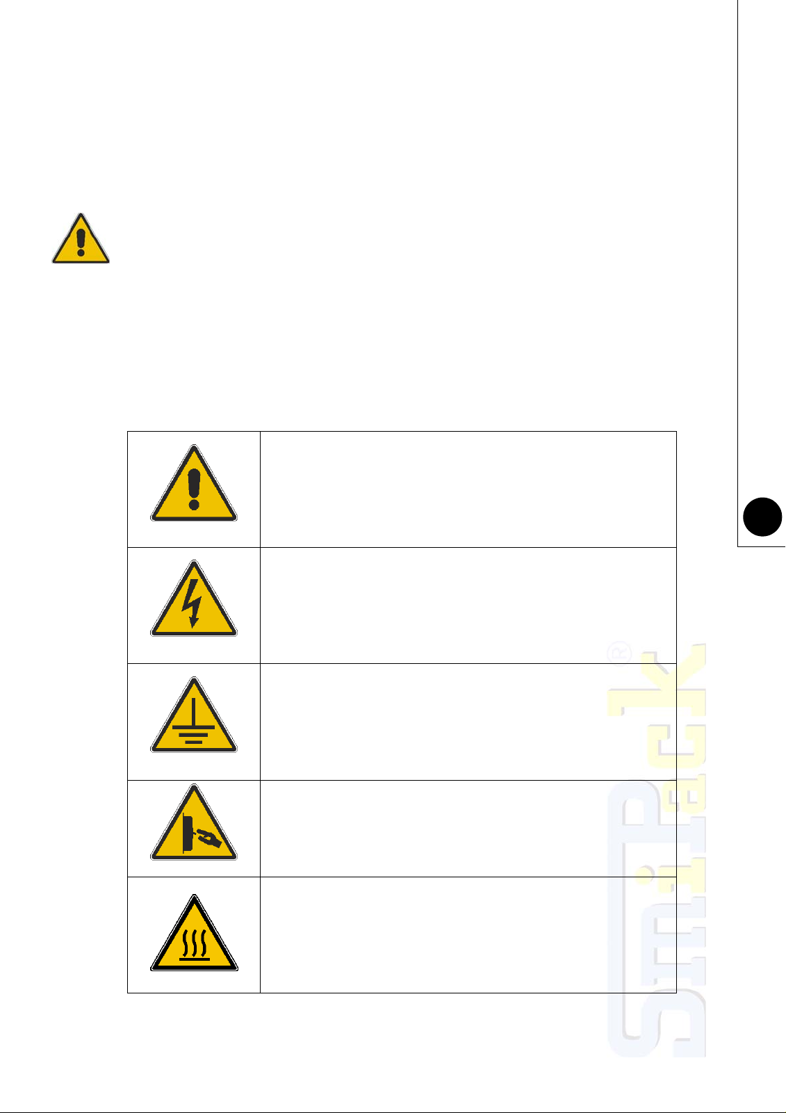
1.5 LEGEND
All instructions and notes contained in this manual are graphically represented in the following
way:
ATTENTION: READ CAREFULLY BEFORE OPERATING.
DANGER OF ELECTROCUTION: HIGH VOLTAGE ZONE.
DANGER OF ELECTROCUTION: EARTHING IS
COMPULSORY.
DANGER OF ELECTROCUTION: EARTHING IS
COMPULSORY.
DANGER OF BURNING DUE TO HIGH TEMPERATURE
SURFACES.

Chapter 1 - Regulations and general instructions
12
WARNING! DON’T TOUCH.
DANGER OF TRAPPING BETWEEN MECHANICAL
MEMBERS.
DANGER OF SHEARING.
DANGER OF INJURY
WARNING! BEFORE OPERATING, CHECK THAT THE
MACHINE TYPE IS THE ONE THAT HAS BEEN BOUGHT.

Use and maintenance manual FP6000CS - FP8000CS
13
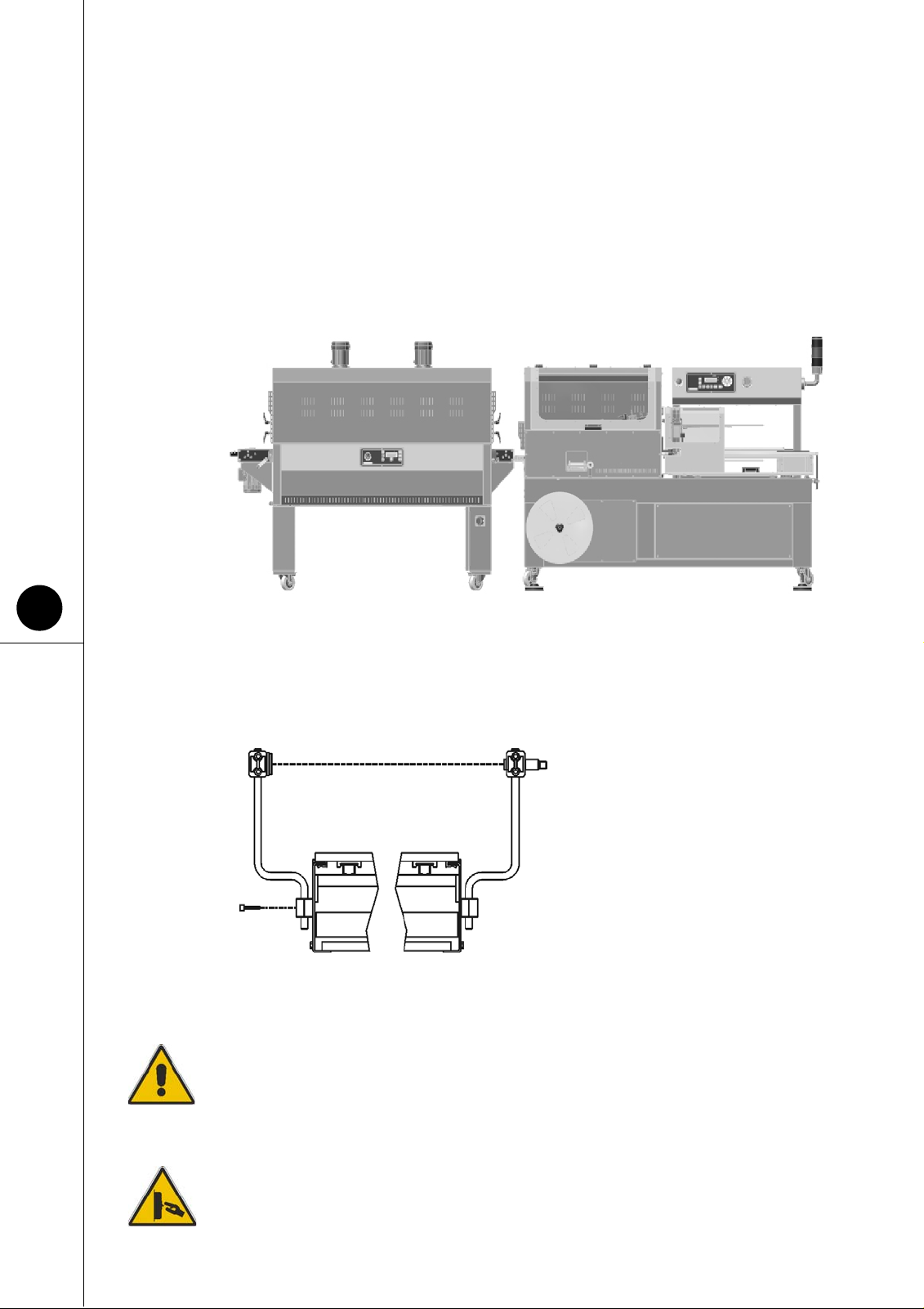
2.1 DESCRIPTION OF THE MACHINE
2.2 SAFETY SYSTEM
CHAPTER 2 - MACHINE INSTALLATION
Fig. 2.1.1
GLOSSARY
1Infeed conveyor belt
2Reel-holder
3Electronic card
4Upper square
5Lower square
6Product guide
7Connecting belt
8Sealing unit
9Film drive unit
10 Scrap winder
11 Belt turnbuckles
12 Electric panel
13 Lifting group
POS. DESCRIPTION
1Plexiglas and sheet movable
protections.
2Fixed protections made of
plexiglas and sheet that
require special equipment to
be removed.
3Safety sensors mounted on
the sealing bar.
4Safety limit switches placed
on the machine frame and
intended to stop the machine
if the movable protections
open unexpectedly.
5Emergency push-button.
Fig. 2.2.1

Chapter 2 - Machine installation
14
2.3 CONTROL SYSTEMS
Pos. Code Description Function
1KZ010166 Flextron-Master
It enables you to set up the machine for the functions it is
expected to perform.
2KZ010160 Flextron-Bell
3KZ010159 Flextron-Power
Base
4KZ010153 Flextron-I/O
5EP010198
EP010200 Emergency push-
button It stops the machine in case of an emergency
6EP010139 Main switch It can turn the machine on and off
7EP300021 Lighting column
The GREEN light signals that the machine is on START.
The RED light signals that the machine is on ALARM. The
BLUE light signals that the machine is on STOP. The
INTERMITTENT GREEN light signals that the machine is
on PAUSE. The INTERMITTENT BLUE light signals that
the sealing bar is heating up
8EF100084 Vertical detection
photoelectric cell It detects and monitors very low packages
9EF100084 Horizontal detection
photoelectric ce It detects and monitors very narrow packages
10 EF100086 Film unwinding
sensor It activates the reel-holder motor when the film is being
dragged.
11 EF100022 Movable belt
detecting sensor
(Only for FP6000CS)
It detects the movable belt group position and prevents the
sealing when the group hinders the sealing bar. If the
sensor is disconnected and the parameter "movable belt" is
activated, the machine will not work.
12 EF100022 The sensor to
activates the
sealing bar safety It detects the presence of an object during the sealing bar's
downstroke
13 EF110006 Position transducer
It allows the card to know the sealing bar position, by
detecting the position of the sealing bar cylinder rod. This
allows the machine to calculate the sealing time, to
deactivate the sealing bar safety sensor during the sealing,
etc…
14 EF100150 Photocell of full
scrap reel Once the scrap reel has reached its full capacity, the
photocell sends the signal to the board. The display will
then show the warning "REEL-SCRAP-FULL"
15 EF010049 High/low package
micro-switch It checks the position of the height adjusting system and
stops
it as soon as the maximum or minimum height is reached.
16 EP010191
EP010199 Upstroke/
downstroke push-
button contacts
It adjusts the machine according to the package, by
modifying the height of the squares, of the dragging roller
and of the sealing bar.
17 EP010193
EP010199 Film pressing
cylinder selector It separates the 2 wheels of the film dragging device, when
the film is positioned.
18 EF100022 Sealing bar position
sensor It determines the opening position of the sealing bar.
19 EF100022 Reel-holder roller
sensor It allows to verify the position of the reel-holder roller. If the
roller is open during the machine operation, the error
“REEL-MOTOR-OPEN“ will be displayed on the board.

Use and maintenance manual FP6000CS - FP8000CS
15
Fig. 2.3.1
Fig. 2.3.3
Fig. 2.3.2
ELECTRICAL
CABINET
Chapter 2 - Machine installation
16
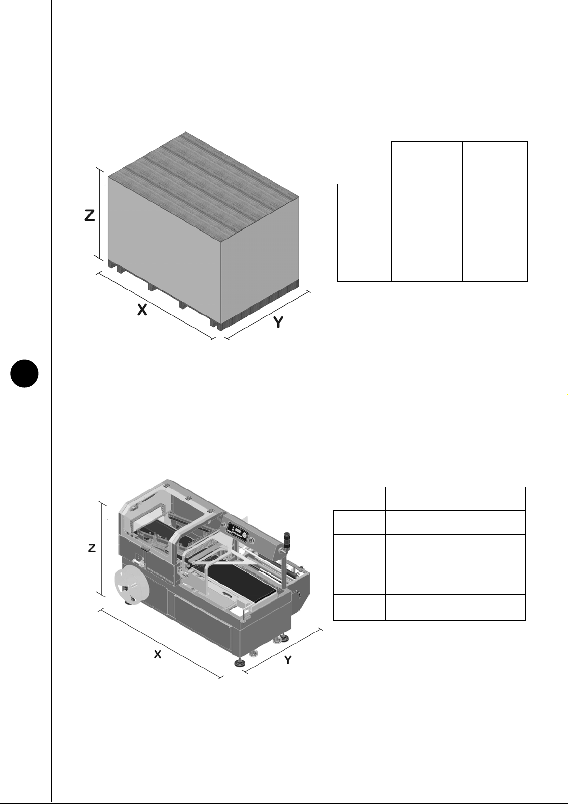
2.4 WEIGHT AND DIMENSIONS OF THE PACKED MACHINE
2.5 WEIGHT AND DIMENSIONS OF THE MACHINE
Fig. 2.4.1
FP6000CS
cardboard case
packaging
FP8000CS
case
packaging
X2200 mm 2650 mm
Y1520 mm 1740 mm
Z1550 mm 1760 mm
WEIGHT Kg660 Kg 810
Fig. 2.5.1
FP6000CS FP8000CS
X2090 mm 2537 mm
Y1433 mm 1633 mm
Z1565-1675
mm 1666-1776
mm
WEIGHT Kg 550 Kg 720
Use and maintenance manual FP6000CS - FP8000CS
17
2.6 TRANSPORT AND UNPACKING
ATTENTION!
Before handling make sure that the hoisting equipment are suitable to lift the load that
has to be handled.
In the case of long storing, place the machine in a sheltered environment with a
temperature between -15°C and +55°C degree of humidity, variable between 30% and
90% without condensation.
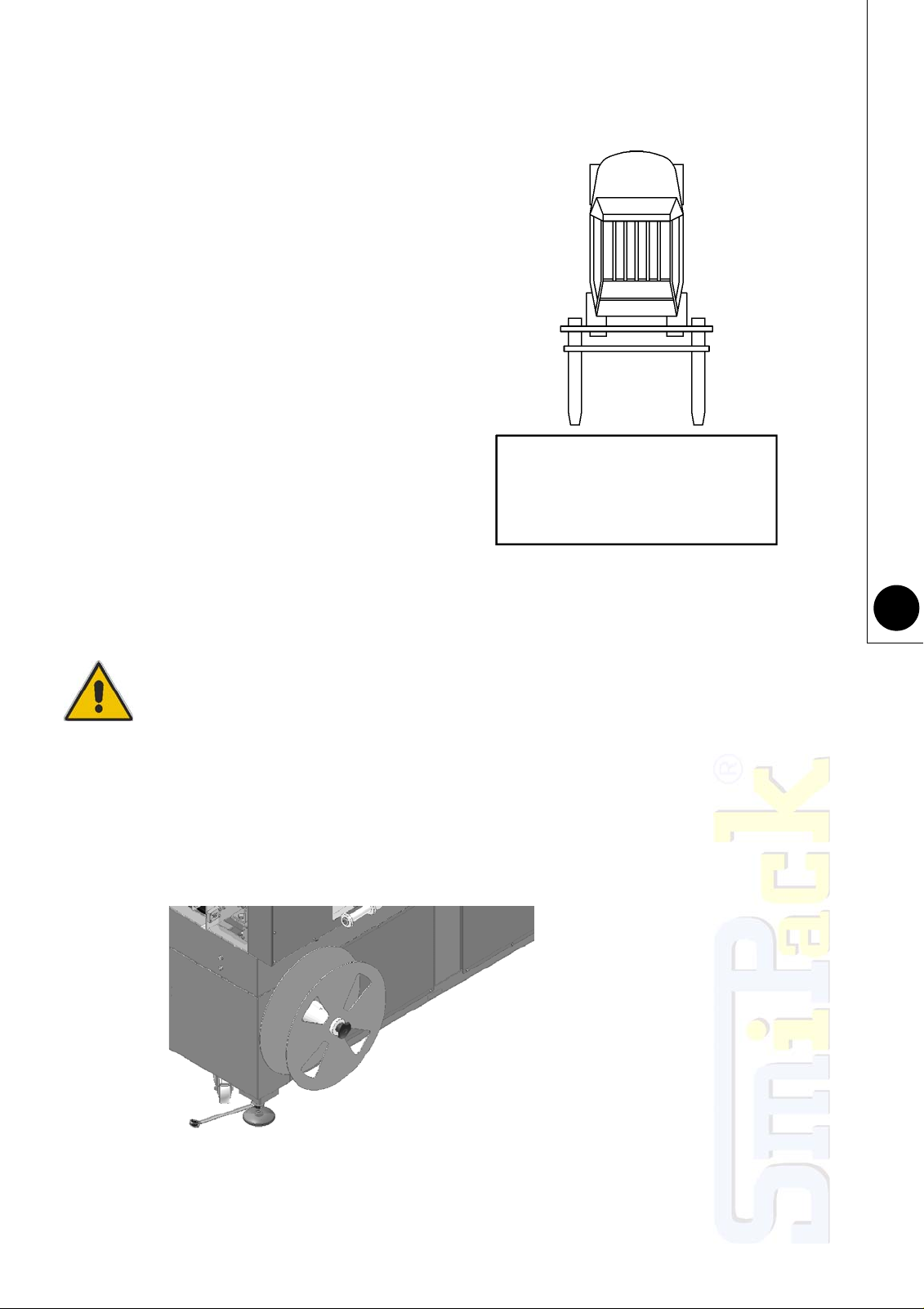
2.7 POSITIONING AND LEVELLING
SMIPACK S.p.A. in function of the means of
transport and of the type of products to be
shipped utilizes packagings adequate to
guarantee the integrity and preservation during
transportation. It is recommended to handle
with great care the machine during transport
and positioning. The forwarder is responsible
for every damage that may occur during
transport. Unpack the unit making sure not to
damage any exposed parts.
The lifting of the machine module must be
carried out by means of hoisting systems
operating from below; due to the packaging
modalities, it is not possible to use hoisting
systems operating from above.
Lift the machinefrom the longer side andadjust
the forks of the forklift at themaximum distance
from each other.
Fig. 2.7.1
Make sure that the floor, in the
installation area, does not
present irregularities that may
prevent the normal and correct
positioning of the machine. Place
a spirit level on the belt's upper
side and then level the machine
using the adjustable support feet
then lock them by tightening the
locknuts
Fig. 2.6.1
Chapter 2 - Machine installation
18
2.8 FP6000CS AND FP8000CS L-SEALER AND T450 TUNNEL
POSITIONING
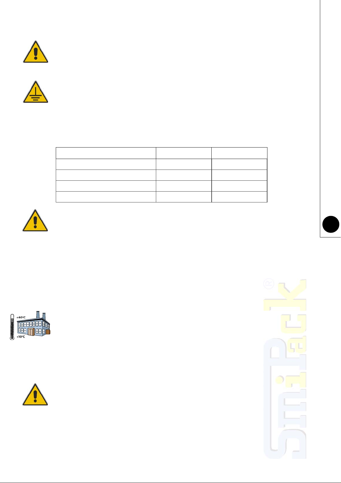
2.9 ASSEMBLING THE ACCUMULATION PHOTOELECTRIC CELLS
(OPTIONAL)
2.10 DEMOLITION AND DISPOSAL
ATTENTION!
The machine does not contain dangerous components or substances that require
particular removal procedures. Regarding the elimination of the various materials, it is
necessary to follow the regulations of the Country in which the tunnel will be
dismantled.
2.11 ELECTRICAL CONNECTIONS
All operations for the connection to the mains must be carried out with no voltage
applied to the machine.
Once the machine has been levelled, place the machine's connecting belt as close as possible
to the tunnel's.
Make sure that the tunnel's belt is kept approximately 1 mm higher than the sealer's, so as to
prevent the falling over of packages at the tunnel inlet zone. Adjust the height by acting on the
adjustable support feet. Position the tunnel in such a way as to have the wrapped package
perfectly centred on the tunnel's belt
Fig. 2.8.1
Fig. 2.9.1
Two groups of photoelectric cells are
supplied along with the machine. One
group is to be placed two meters ahead of
the machine inlet and is intended to detect
any possible end of flux. The other group
is to be placed two meters after the tunnel
and is meant to detect any possible
product accumulation. After placing a level
on the upper part of the frame, level the
machine using the adjustable support feet
then lock them by tightening the locknuts.
Use and maintenance manual FP6000CS - FP8000CS
19
ATTENTION!
In the case which someone wants access to the electrical system, remember to turn off
the power supply and wait at least 5 minutes before operating.
Earthening is compulsory!
The machine's connection to the mains must be carried out in thorough compliance
with the regulations of the user's country.
Make sure that the frequency and voltage of the machine's power supply (as indicated
on the nameplate to be found on the rear of the machine) correspond to the mains'.
2.12 TECHNICAL DATA FOR THE ELECTRIC CONNECTION
ATTENTION!
The machine's supply line must be equipped with a thermal magnetic circuit breaker
capable of withstanding the rated values stated in table 2.12.1
2.13 CONDITIONS OF USE
Make sure that there is enough space for easy application and maintenance.
THE MACHINE NEEDS AN INSTALLATION IN A CLOSED AND WELL AIRED
SURROUNDING, WHERE THERE ARE NOT ANY EXPLOSION OR FIRE DANGEROUS.
THE MINIMUM LIGHTING MUST BE 300 LUX.
Make sure that there is enough space for easy application and maintenance. Position the
machine in the planned space with no humidity, flammable materials, gas, and explosives and
making sure that it is level on the floor.
We suggest operating temperatures varying from +10°C to +40°C with a relative humidity from
30% to 80% with no condensation.
The airborne noise is lower than 70 dB.
FP6000CS and FP8000CS L-Sealer's IP class rating = IP54
ATTENTION!
The pressure and the plate acoustical power of the machine can change depending on
the material of containers to be packaged. Therefore, the user must perform an
assessment on the noise exposure of his personnel in accordance with the types of
packages worked, so as to equip his operators with suitable personal protection
equipment.
Tab. 2.12.1
FP6000CS FP8000CS
RATED VOLTAGE 230 V 230 V
RATED FREQUENCY 50 Hz 50 Hz
RATED POWER 3250 W 3850 W
RATED CURRENT 13,5 A 16 A

White page
This manual suits for next models
1
Table of contents
Other Smipack Industrial Equipment manuals


Popular Industrial Equipment manuals by other brands

SpinTouch
SpinTouch RapidScreen Wall Mount Assembly instructions

Grundfos
Grundfos UPE 2000 FZ Series Installation and operating instructions

ICC
ICC RONER R PLUS Operating and maintenance manual

RenewAire
RenewAire BR Series quick start guide

Reflex
Reflex Refix DD Series Instructions for use

SCHUNK
SCHUNK PGH 30 Repair instructions


MB
MB 700 Series Operation manual

Bühler technologies
Bühler technologies GAS 222.11 Ex2 Installation & operation instructions

Siemens
Siemens SINUMERIK Equipment manual

WAMGROUP
WAMGROUP EXTRAC RBB Installation operation & maintenance

General Measure
General Measure Checkweigher user manual

STEPCRAFT
STEPCRAFT D Series manual