Newport FMS Series User manual

Linear
Metrology Stages
FMS Series
USER’SMANUAL
G
U
A
R
A
N
T
E
E
D
S
P
E
C
I
F
I
C
A
T
I
O
N
S

EDH0267En1041 — 12/18 ii
FMS Series Linear Metrology Stages
Warranty
Newpor Corpora ion warran s his produc o be free from defec s in
ma erial and workmanship for a period of 1 year from he da e of
shipmen . If found o be defec ive during he warran y period, he produc
will ei her be repaired or replaced a Newpor ’s discre ion.
To exercise his warran y, wri e or call your local Newpor represen a ive,
or con ac Newpor headquar ers in Irvine, California. You will be given
promp assis ance and re urn ins ruc ions. Send he ins rumen ,
ranspor a ion prepaid, o he indica ed service facili y. Repairs will be
made and he ins rumen re urned, ranspor a ion prepaid. Repaired
produc s are warran ed for he balance of he original warran y period, or
a leas 90 days.
Limitation of Warranty
This warran y does no apply o defec s resul ing from modifica ion or
misuse of any produc or par .
This warrant is in lieu of all other warranties, expressed or implied,
including an implied warrant of merchantabilit or fitness for a
particular use. Newport Corporation shall not be liable for an indirect,
special, or consequential damages.
b Newport Corporation, Irvine, CA. All rights reserved.
Original instructions.
No part of this document ma be reproduced or copied without the prior
written approval of Newport Corporation. This document is provided for
information onl , and product specifications are subject to change without
notice. An change will be reflected in future publishings.
CAUTION
Warran y does no apply o damages resul ing from:
• Incorrec usage:
– Load on he s age grea er han maximum specified load.
– Carriage speed higher han specified speed.
–Improper grounding.
¬ Connec ors mus be properly secured.
¬ When he load on he s age represen s an elec rical risk, i mus
be connec ed o ground.
– Excessive or improper can ilever loads.
• Modifica ion of he s age or any par hereof.
CAUTION
Please ret rn eq ipment in
the original (or eq ivalent)
packing.
Yo will be responsible for
damage inc rred from
inadeq ate packaging if the
original packaging is not
sed.
© 2018

iii EDH0267En1041 — 12/18
FMS Series Linear Metrology Stages
Table of Contents
Warranty .................................................................................................................ii
EC Declaration of Conformity...............................................................................v
Definitions and Symbols.......................................................................................vi
Warnings ...............................................................................................................vii
Caution .................................................................................................................viii
1.0 — Introduction.................................................................................1
2.0 — Description ...................................................................................2
2.1 Design Details ............................................................................................2
3.0 — Characteristics............................................................................3
3.1 Definitions..................................................................................................3
3.2 Mechanical Specifications .......................................................................4
3.3 Load Specification Definitions.................................................................4
3.4 Load Characteristics and Stiffness .........................................................5
3.5 Stage Weights ............................................................................................5
4.0 — Drives and Motors ....................................................................6
4.1 Stepper Drive Versions ............................................................................6
4.2 DC-Servo Drive Version............................................................................6
4.3 Sensor Position..........................................................................................7
4.4 Feedback Signal Position .........................................................................7
4.5 Pinouts........................................................................................................8
4.6 MCAB-3 Cable ............................................................................................9
4.7 MSCABLE-3 Cable......................................................................................9
4.8 MSCABLE-10 Cable....................................................................................9
5.0 — Connection to Newport Controllers..............................10
5.1 Warnings on Controllers ........................................................................10
5.2 Connection...............................................................................................11
5.3 Cables .......................................................................................................11
5.4 MSCABLE-3 Cable....................................................................................12
5.5 MCAB-3 Cable ..........................................................................................12
6.0 — Connection to Non-Newport Electronics ....................13
6.1 Connections.............................................................................................13
7.0 — Dimensions.................................................................................14

EDH0267En1041 — 12/18 iv
FMS Series Linear Metrology Stages
8.0 — Maintenance ..............................................................................15
8.1 Maintenance ............................................................................................15
8.2 Repair .......................................................................................................15
8.3 Calibration ...............................................................................................15
Service Form .........................................................................................................17

v EDH0267En1041 — 12/18
FMS Series Linear Metrology Stages
FMS Series
EU Declaration of Conformity
following Annex II-1A
of Directive 2006/42/EC on machinery
The manufacturer:
MICRO-CONTROLE Spectra-Physics,
9, rue du Bois Sauvage
91055 Évry CEDEX, FRANCE
Hereby declares that the machinery:
yDescription: " FMS"
yFunction: PRECISION LINEAR STAGES
yModels: FMS100/200/300/CC/PP/PPHA.
– the technical file of which was compiled by:
Mr Hervé LE COINTE , Quality Director,
MICRO-CONTROLE Spectra-Physics, Zone Industrielle - B.P.29
F-45340 Beaune La Rolande France
– complies with all the relevant provisions of the Directive 2006/42/EC on machinery.
– complies with all the relevant provisions of the Directive 2014/30/EU relating to electro-
magnetic compatibility.
– complies with all the relevant provisions of the Directive 2011/65/EU relating to RoHS2.
– was designed and built in accordance with the following harmonised standards:
yNF EN 61326-1:2013 « Electrical equipment for measurement, control and
laboratory use – EMC requirements – Part 1: General requirements »
yNF EN 55011:2010/A1:2011 Class A
– was designed and built in accordance with the following other standards:
yNF EN 61000-4-2
yNF EN 61000-4-3
yNF EN 61000-4-4
yNF EN 61000-4-5
yNF EN 61000-4-6
ORIGINAL DECLARATION
Done in Beaune La Rolande on 16 May 2017
Hervé LE COINTE
Quality Director
DC1-EN rev:A
EC Declaration of Conformity

EDH0267En1041 — 12/18 vi
FMS Series Linear Metrology Stages
Definitions and ymbols
The following erms and symbols are used in his documen a ion and also
appear on he produc where safe y-rela ed issues occur.
General Warning or Caution
The exclama ion symbol may appear in warning and cau ion ables in his
documen . This symbol designa es an area where personal injury or
damage o he equipmen is possible.
The following are defini ions of he Warnings, Cau ions and No es ha may
be used in his manual o call a en ion o impor an informa ion regarding
personal safe y, safe y and preserva ion of he equipmen , or impor an
ips.
WAR N IN G
Warning indicate a potentially dangerou ituation which can re ult in
bodily harm or death.
CAUTION
Caution indicate a potentially hazardou ituation which can re ult in
damage to product or equipment.
NOTE
Note indicate additional information that mu t be con idered by the
u er or operator.
European Union CE Mark
The presence of he CE Mark on Newpor Corpora ion equipmen means
ha i has been designed, es ed and cer ified as complying wi h all
applicable European Union (CE) regula ions and recommenda ions.
Warning and Caution
ATTENTION
Thi tage i a Cla A device. In a re idential environment, thi device
can cau e electromagnetic interference. In thi ca e, uitable mea ure
mu t be taken by the u er.

vii EDH0267En1041 — 12/18
FMS Series Linear Metrology Stages
Warnings
WARNING
The motion of objects of all types carries potential risks for operators.
Ensure the protection of operators by prohibiting access to the dangerous
area and by informing the personnel of the potential risks involved.
WAR N IN G
D n t use this stage when its m t r is emitting sm ke r is unusually
h t t the t uch r is emitting any unusual d r r n ise r is in any
ther abn rmal state.
St p using the stage immediately, switch ff the m t r p wer and then
disc nnect the electr nics p wer supply.
After checking that sm ke is n l nger being emitted c ntact y ur
Newp rt service facility and request repairs. Never attempt t repair the
stage y urself as this can be danger us.
WAR N IN G
Make sure that this stage is n t exp sed t m isture and that liquid d es
n t get int the stage.
Nevertheless, if any liquid has entered the stage, switch ff the m t r
p wer and then disc nnect the electr nics fr m p wer supply.
C ntact y ur Newp rt service facility and request repairs.
WAR N IN G
D n t insert r dr p bjects int this stage, this may cause an electric
sh ck, r l ck the drive.
D n t use this stage if any f reign bjects have entered the stage.
Switch ff the m t r p wer and then disc nnect the electr nics p wer
supply.
C ntact y ur Newp rt service facility f r repairs.
WAR N IN G
D n t place this stage in unstable l cati ns such as n a w bbly table r
sl ping surface, where it may fall r tip ver and cause injury.
If this stage has been dr pped r the case has been damaged, switch ff
the m t r p wer and then disc nnect the electr nics p wer supply.
C ntact y ur Newp rt service facility and request repairs.
WAR N IN G
D n t attempt t m dify this stage; this may cause an electric sh ck r
d wngrade its perf rmance.
WAR N IN G
D n t exceed the usable depth indicated n the m unting h les (see
secti n “Dimensi ns”). L nger screws can damage the mechanics r
cause a sh rt-circuit.

EDH0267En1041 — 12/18 viii
FMS Series Linear Metrology Stages
Caution
CAUTION
Do not place this stage in a hostile environment such as X-Rays, har
UV,… or in any vacuum environment.
CAUTION
Do not place this stage in a location affecte by ust, oil fumes, steam or
high humi ity. This may cause an electric shock.
CAUTION
Do not leave this stage in places subject to extremely high temperatures
or low temperatures. This may cause an electric shock.
• Operating temperature: +10 to +35 °C
• Storage temperature: -10 to +40 °C (in its original packaging)
CAUTION
Do not move this stage if its motor power is on.
Make sure that the cable to the electronics is isconnecte before
moving the stage. Failure to o so may amage the cable an cause an
electrical shock.
CAUTION
Be careful that the stage is not bumpe when it is being carrie . This
may cause it to malfunction.
CAUTION
When han ling this stage, always unplug the equipment from the power
source for safety.
CAUTION
When the carriage is in its en -of-run position, it is strongly recommen e
not to go beyon this point as this may amage the stage mechanism.
CAUTION
Contact your Newport service facility to request cleaning an
specification control every year.
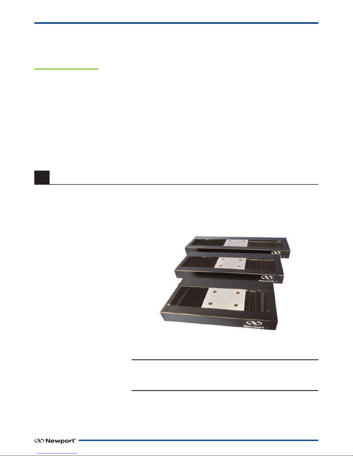
1 EDH0267En1041 — 12/18
FMS Series Linear Metrology Stages
Linear Metrology Stages
FMS Series
1.0 —Introduction
This manual provides operating instructions for the stage that you have
purchased in the FMS Series:
3 travel ranges of FMS stages.
RECOMMENDATION
We recommend you read carefully the chapter “Connection to
electronics” before using the FM stage.
• FMS-PP
• FMS-PPHA
• FMS-CC

EDH0267En1041 — 12/18 2
FMS Series Linear Metrology Stages
2.0 —Description
The FMS series of precision linear stages is ewport’s latest innovation in
high precision motion control technology. It addresses the unique needs
of surface metrology applications for smooth motion, low noise, high
straightness and flatness. The FMS linear stages run highly flat and
straight and combined with steel construction, enable higher accuracy
performance. Travel options include 100 mm, 200 mm and 300 mm and can
be ordered with either a DC or stepper motor. As with all ewport
motorized stages, there is a wide choice of integrated controller/driver
products, ranging from the single axis SMC100, to the 3-axis ESP301 and
high-performance 8-axis XPS Universal Controller.
Featuring steel construction, the FMS linear stages have a very distinct
advantage over other stages made with aluminum. It is well known that
steel expands less than aluminum when subjected to temperature
fluctuations in the operating environment. In addition, a combination of
steel and aluminum in the construction of a stage introduces a
phenomenon called bi-metallic bending, caused by the different thermal
expansion coefficients of metals. Both these reasons led to the use of steel
exclusively in the base and other components of the FMS stages. Since all
FMS components are made from steel, all these components are expected
to expand at the same rate when the operating temperature fluctuates,
thereby eliminating bi-metallic bending and the associated inaccuracies
and non-flat behavior.
The cross roller bearings in the FMS come standard with an anti-creep
feature that ensures high reliability by eliminating bearing cage migration
and the need for re-centering the bearings. Moreover, this enables
optimum bearing contact that results in superior repeatability of
straightness, flatness, pitch and yaw over the life of the FMS.
The FMS stages have a nominal speed of up to 100 mm/s, easily improving
throughput compared to other products in the market. Controlling with
ewport integrated motion controllers and drivers like the SMC100 and
ESP301 (CC and PP versions) or the XPS (all versions), adds more
flexibility in gathering metrology data.
The FMS linear stages are exceptional solutions for applications in surface
metrology, surface profilometry and tribology.
2.1 Design Details
Base Material Stainless Steel
Bearings Crossed Roller Bearings
Drive Mechanism 8 mm, precision ground ball screw
Drive Screw Pitch (mm) 2
Feedback DC: Screw mounted rotary encoder, 4000 cts/rev, index pulse
PP: No feedback
PPHA: Steel scale, 50 nm
Origin PP: optical, located ~9.5 mm from negative software limit
CC & PPHA: Optical, located ~10.5 mm from negative software limit
Drive Type DC Servo
Stepper
Cable (m) 3 (included)

3 EDH0267En1041 — 12/18
FMS Series Linear Metrology Stages
3.0 —Characteristics
3.1 Definitions
Specificatio s of our products are established i refere ce to ISO 230
sta dard part II “Determi atio of accuracy a d repeatability of
positio i g umerically co trolled axes”.
This sta dard gives the defi itio of positio u certai ty which depe ds
o the 3 followi g parameters:
Absolute Accuracy
Differe ce betwee ideal positio a d real positio .
Accuracy
Differe ce betwee ideal positio a d real positio after the compe satio
of li ear errors.
Li ear errors i clude: cosi e errors, i accuracy of screw or li ear scale
pitch, a gular deviatio at the measuri g poi t (Abbe error) a d thermal
expa sio effects. All Newport motio electro ics ca compe sate for
li ear errors.
The relatio betwee absolute accuracy a d o -axis accuracy is as follows:
Absolute Accuracy = Accuracy + Correction Factor xTravel
Repeatability
Ability of a system to achieve a comma ded positio over ma y attempts.
Reversal Value (Hysteresis)
Differe ce betwee actual positio values obtai ed for a give target
positio whe approached from opposite directio s.
Minimum Incremental Motion (MIM or Sensitivity)
The smallest i creme t of motio a device is capable of deliveri g
co siste tly a d reliably.
Resolution
The smallest i creme t that a motio device ca theoretically move
a d/or detect. Resolutio is ot achievable, whereas MIM, is the real
output of a motio system.
Yaw, Pitch
Rotation of carriage around the Z axis (Yaw) or Y axis (Pitch), when it
moves.
The testing of accuracy, repeatability, and reversal error are made
systematically with test e uipment in controlled environment (20 ±1 °C).
A linear cycle with 21 data points on the travel and 4 cycles in each
direction gives a total of 168 points.
Guaranteed and Typical Specifications
Guaranteed maximum performance values are verified per Newport's A167
metrology test procedure. For more information, please consult the
metrology tutorial section in the Newport catalog or at www.newport.com

EDH0267En1041 — 12/18 4
FMS Series Linear Metrology Stages
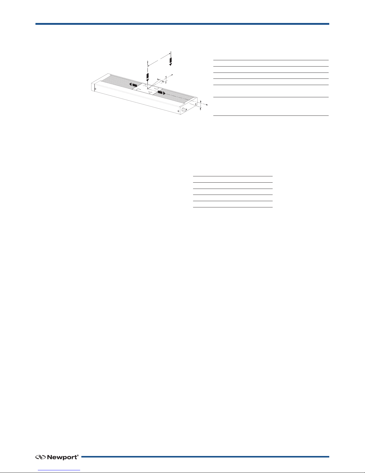
3.2 Mechanical pecifications
CAUTION
To reach the specifications stated, stages must be fixed on a plane with
a flatness better than the stage flatness guaranteed value or fixed using
the 4 washers (Ø 16 mm and thickness 0.1 mm) delivered with the
stage. The M6 screws torque to fix the stage must be 5 Nm.
3.3 Load pecification Definitions
Normal Load Capacity (Cz)
Maximum load a stage can move while maintaining specifications.
This value is given with speed and acceleration specified for each stage,
and with a load perpendicular to bearings.
Axial Load Capacity (±Cx)
Maximum load along the direction of the drive train.
Off-Centered Load (Q)
Maximum cantilever-load a stage can move.
FMC-CC FMC-PP FMC-PPHA
Travel Range (mm) 100; 200; 300
Minimum ncremental Motion (µm) 0.5 0.1 (1) 0.1
Uni-directional Repeatability,
Typical (Guaranteed) (µm) ±0.40 (±0.75) ±0.35 (±0.75) ±0.06 (±0.10)
Bi-directional Repeatability (2),
Typical (Guaranteed) (µm) ±0.8 (±1.5) ±1.3 (±2.25) ±0.15 (±0.25)
Maximum Speed (mm/s) 100 20 50
FMS100 FMS200 FMS300
Accuracy (2), -CC and -PP ±1.5 (±3.0) ±2.0 (±5.0) ±2.5 (±6.5)
Typical (Guaranteed) (µm) -PPHA ±0.2 (±0.5) ±0.4 (±1.0) ±0.5 (±1.5)
Straightness, Flatness (2),
Typical (Guaranteed) (µm) ±0.25 (±0.75) ±0.5 (±1.5) ±1.0 (±3.0)
Pitch (2) (3), Typical (Guaranteed) (µrad) ±15 (±40) ±20 (±50) ±30 (±60)
Yaw (2) (3), Typical (Guaranteed) (µrad) ±4.0 (±10) ±5.0 (±15) ±6.0 (±20)
1)0.1 µm with XPS; 0.5 µm with SMC100PP and ESP301.
2)For the definition of Typica and Guaranteed specifications see “Motion Basics Termino ogy & Standards” Tutoria
at www.newport.com
3)To obtain arcsec units, divide µrad va ue by 4.8.
G
U
A
R
A
N
T
E
E
D
S
P
E
C
I
F
I
C
A
T
I
O
N
S
FMS-PP PPHA FMS-CC
Specified Speed (mm/s) 20 50 100
Specified Acceleration (mm/s2) 80 200 400
5 EDH0267En1041 — 12/18
FMS Series Linear Metrology Stages
3.4 Load Characteristics and tiffness
3.5 tage Weights
Weights indicated into the below table are average values for stages with a
typical drive unit installed.
The stage weight below does not include the cable.
The weight difference between drive units is not significant.
Weight [lb (kg)]
FMS100 14.3 (6.5)
FMS200 17.0 (7.7)
FMS300 19.6 (8.9)
3-meter MSCABLE-3 Cable 0.66 (0.3)
3-meter MCAB-3 Cable 1.32 (0.6)
Cz, Normal center load capacity on bearings 150 N
±Cx, Axial load capacity <30 N (1)
kax, Compliance in roll 3 µrad/Nm
kay, Compliance in pitch 2 µrad/Nm
kaz, Compliance in yaw 2 µrad/Nm
Q, Off-center load Q ≤Cz ÷ (1 + D/80)
with D = Cantilever distance (mm)
1) Note
Reversible drive c ain: Not recommended for vertical use
unless counterweig ed.
kαy
Q
D
kαz
X
Z
Cz
kαx
Y
+Cx
–Cx
EDH0267En1041 — 12/18 6
FMS Series Linear Metrology Stages
4.0 —Drives and Motors
4.1 tepper Drive Versions
FMS-PP: This version is not equipped with an encoder.
The micro-step is equivalent to 1/100 of the full-step.
FMS-PPHA: This version is equipped with a steel scale encoder.
For these stages, the micro-step is equivalent to 1/200 of the
full-step.
tepper Motor Performance pecifications and Characteristics
Command ignals for the tepper Motors
4.2 DC- ervo Drive Version
One DC-motor configurations is available: FMS-CC.
This version is equipped with a 4000 cts/rev. rotary encoder located
directly on the screw.
DC-Motor Performance pecifications and Characteristics
Command ignals for the DC-Motors
In the above drawings, + Motor signal is referred to – Motor signal.
➀When the stage moves in + Direction, the + Motor voltage is higher than
– Motor voltage.
➁When the stage moves in – Direction, the + Motor voltage is lower than
– Motor voltage.
0 2
-1
1
10.5 1.5
Step 1 2 3 4 5 8 7 8
+Phase 1 + + – – + + – –
–Phase 1 – – + + – – + +
+Phase 2 – + + – – + + –
–Phase 2 + – – + + – – +
Direction –MOTION +
+ Phase 1
– Phase 1
+ Phase 2
– Phase 2
Direction +
Resolution Speed Nomin l M x RMS M x. Pe k Resist nce Induct nce T chometer
(µm) (mm/s) Volt ge (V) Current (A) Current (A) (Ω) (mH) Const. (V/krpm)
FMS-CC 0.5 100 48 0.9 1.6 2.52 0.51 –
Direction +
+V
+ Motor
– Motor –V
MOTION Direction +
MOTIONDirection –
Resolution Speed Angle by Step RMS Current Resist nce Induct nce
(µm) (mm/s) (°) per Ph se (A) (Ω) (mH)
FMS-PP 0.1 20 1.8 0.71 1.7 2.8
FMS-PPHA 0.05 50 1.8 0.71 1.7 2.8

7 EDH0267En1041 — 12/18
FMS Series Linear Metrology Stages
4.3 ensor Position
NOTE
• End-of-Run and Mechanical Zero are 5 V open collector type.
• Use of the Index Pulse provides a repeatable Home Position at ±1 step.
• There is no index pulse on the FM -PP.
• On the FM -CC, there is one index pulse every 2 mm and homing will
use the first pulse to the right of the Mechanical Zero. It is adjusted to
about 1 mm.
• There is one index pulse every 25 mm on FM -PPHA. Homing will use
the first pulse to the right of the Mechanical Zero and is adjusted to
about 1 mm.
CAUTION
“End-of-Run” and “Mechanical Zero” are active signals and should not
be connected to any other source.
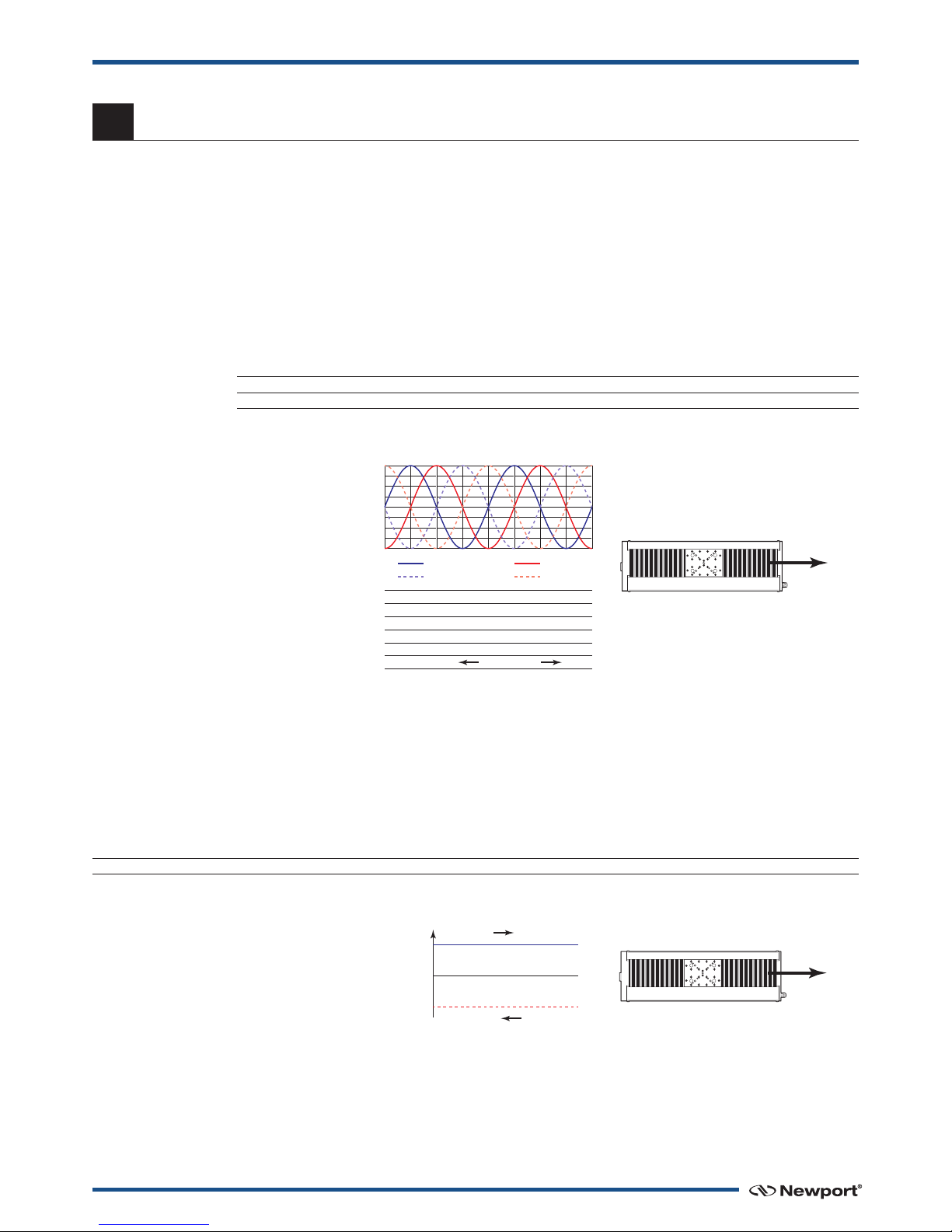
4.4 Feedback ignal Position
On FMS-CC stages, the incremental sensor operates following the
photoelectric measurement principle, with a disk including slides.
Stage Travel Range
Negative Software Limit Positive Software Limit
Home Position (Origin)
near the – end-of-run
Motion Direction +
–EOR Limit
Mechanical
Zero
Index Pulse
Index Pulse
+ EOR Limit
1mm
0.5 mm 0.5 mm
FMSCC: 2 mm
FMSPPHA: 25 mm
Direction +
0
1
Encoder
Phase A
0
1
Encoder
Phase A
1234
0
1
Encoder
Phase B
0
1
Encoder
Phase B
Direction – MOTION Direction +

EDH0267En1041 — 12/18 8
FMS Series Linear Metrology Stages
When the sensor shaft turns, the sensor generates square signals in
quadrature, sent to pins #19, #20, #23 and #24 of the 25-pin Sub-D connector.
“Encoder” and “Index Pulse” are “differential pair” (type RS-422) type
output signals. Using these signals permits a high immunity to noise.
Emission circuits generally used by ewport are 26LS31 or MC3487.
Reception circuits to use are 26LS32 or MC3486.
4.5 Pinouts
The pinout diagrams for the FMS stages SUB-D connector are shown below.
SUD-D25 OR SUB-D15
Encoder Phase A 19 13
Encoder Phase A 23 6
Encoder Phase B 20 14
Encoder Phase B 24 7
Index Pulse Phase I 15 15
Index Pulse Phase I 25 8
21 12
22 5
NEWPORT
STAGE USER
CONNECTOR PIN #
Output Signals
Encoders
& Sensors
Power Supply
+5 V 5%
150 mA max.
0 V
}
13
25
14 1
FMS-PPHA
1 + Ph se 1
2 + Ph se 1
3 – Ph se 1
4 – Ph se 1
5 + Ph se 2
6 + Ph se 2
7 – Ph se 2
8 – Ph se 2
9 N.C.
10 N.C.
11 N.C.
12 N.C.
13 Mech nic l Zero
14 Ground
15 Index Pulse I
16 0 V
17 + End-of-Run
18 – End-of-Run
19 Encoder Ph se A
20 Encoder Ph se B
21 +5 V
22 0 V
23 Encoder Ph se /A
24 Encoder Ph se /B
25 Index Pulse /I
FMS-CC
1 N.C.
2 + Motor
3 Mech nic l Zero
4 – End-of-Run
5 0 V
6 Encoder Ph se /A
7 Encoder Ph se /B
8 Index Pulse /I
9 N.C.
10 – Motor
11 + End-of-Run
12 +5 V
13 Encoder Ph se A
14 Encoder Ph se B
15 Index Pulse I
FMS-PP
1 + Ph se 1
2 + Ph se 2
3 Mech nic l Zero
4 – End-of-Run
5 0 V
6 N.C.
7 N.C.
8 N.C.
9 – Ph se 1
10 – Ph se 2
11 + End-of-Run
12 +5 V
13 N.C.
14 N.C.
15 N.C.
8
15
91
9 EDH0267En1041 — 12/18
FMS Series Linear Metrology Stages
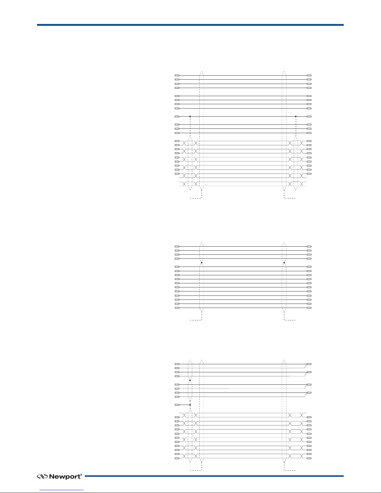
4.6 MCAB-3 Cable
This cable is supplied with each FMS-PPHA stages.
4.7 M CABLE-3 Cable
This cable is supplied with each FMS-PP and FMS-CC stage.
4.8 M CABLE-10 Cable
Optional 10-meter cable for FMS-PP or FMS-CC stages.
CONNECTED
TO THE CAP
CONNECTED
TO THE CAP
SUB-D25M
CONNECTOR
1
2
3
4
5
6
7
8
14
22
21
16
19
23
20
24
15
25
17
18
13
SUB-D25F
CONNECTOR
1
2
3
4
5
6
7
8
14
22
21
16
19
23
20
24
15
25
17
18
13
(0.6 MM2) WHITE 1
(0.6 MM2)WHITE 2
(0.6 MM2) WHITE 3
(0.6 MM2) WHITE 4
(0.6 MM2) WHITE 6
(0.6 MM2)WHITE 7
(0.6 MM2) WHITE 8
(0.6 MM2) WHITE 9
(0.6 MM2) WHITE 5
(0.6 MM2) WHITE 10
(0.6 MM2) WHITE 11
(0.6 MM2)WHITE 12
(0.09 MM2) WHITE
(0.09 MM2) BROWN
(0.09 MM2) GREEN
(0.09 MM2)YELLOW
(0.09 MM2) GREY
(0.09 MM2) PINK
(0.09 MM2) BLUE
(0.09 MM2) RED
(0.09 MM2)BLACK
(0.09 MM2) PURPLE
(0.09 MM2) ORANGE
(0.09 MM2) BLUE
(AWG20) WHITE 1
(AWG20) WHITE 2
(AWG20) WHITE 3
(AWG20) WHITE 4
(AWG20) WHITE 6
(AWG20) WHITE 7
(AWG20) WHITE 8
(AWG20) WHITE 9
(AWG20) WHITE 5
(AWG20) WHITE 10
(AWG20) WHITE 11
(AWG20) WHITE 12
(AWG28) WHITE
(AWG28) BROWN
(AWG28) GREEN
(AWG28) YELLOW
(AWG28) GREY
(AWG28) PINK
(AWG28) BLUE
(AWG28) RED
(AWG28) BLACK
(AWG28) PURPLE
(AWG28) ORANGE
(AWG28) BLUE
SUB-D25M
CONNECTOR
1
3
5
7
21
22
13
17
18
19
23
20
24
15
25
SUB-D15F
CONNECTOR
1
9
2
10
12
5
3
11
4
13
6
14
7
15
8
(0.25 MM2)WHITE
(0.25 MM2) BROWN
(0.25 MM2) YELLOW
(0.25 MM2) GREEN
(0.14 MM2)PINK
(0.14 MM2) GRAY
(0.05 MM2) BROWN
(0.05 MM2) YELLOW
(0.05 MM2) GREEN
(0.05 MM2)RED
(0.05 MM2) BLUE
(0.05 MM2) PINK
(0.05 MM2) GRAY
(0.05 MM2) BLACK
(0.05 MM2) WHITE
(AWG23) WHITE
(AWG23) BROWN
(AWG23) YELLOW
(AWG23) GREEN
(AWG26) PINK
(AWG26) GRAY
(AWG30) BROWN
(AWG30) YELLOW
(AWG30) GREEN
(AWG30) RED
(AWG30) BLUE
(AWG30) PINK
(AWG30) GRAY
(AWG30) BLACK
(AWG30) WHITE
CONNECTED
TO THE CAP
CONNECTED
TO THE CAP
CONNECTED
TO THE CAP
CONNECTED
TO THE CAP
SUB-D25M
CONNECTOR
1
2
3
4
5
6
7
8
14
13
21
22
17
18
19
23
20
24
15
25
SUB-D15F
CONNECTOR
1
9
2
10
3
12
5
11
4
13
6
14
7
15
8
(0.34 MM2) WHITE
(0.34 MM2) BROWN
(0.34 MM2) GREEN
(0.34 MM2) YELLOW
(0.34 MM2) WHITE
(0.34 MM2) BROWN
(0.34 MM2) GREEN
(0.34 MM2) YELLOW
(0.14 MM2) WHITE
(0.14 MM2) GREEN
(0.14 MM2) ORANGE
(0.14 MM2) WHITE/BLACK
(0.14 MM2) YELLOW
(0.14 MM2) PURPLE
(0.14 MM2) BLUE
(0.14 MM2) GRAY
(0.14 MM2) BROWN
(0.14 MM2) NATURAL
(0.14 MM2) RED
(0.14 MM2) BLACK
(AWG22) WHITE
(AWG22) BROWN
(AWG22) GREEN
(AWG22) YELLOW
(AWG22) WHITE
(AWG22) BROWN
(AWG22) GREEN
(AWG22) YELLOW
(AWG26) WHITE
(AWG26) GREEN
(AWG26) ORANGE
(AWG26) WHITE/BLACK
(AWG26) YELLOW
(AWG26) PURPLE
(AWG26) BLUE
(AWG26) GRAY
(AWG26) BROWN
(AWG26) NATURAL
(AWG26) RED
(AWG26) BLACK
EDH0267En1041 — 12/18 10
FMS Series Linear Metrology Stages
5.0 —Connection to Newport Controllers
NOTE
Visit www.newport.com for compatible Newport controllers.
5.1 Warnings on Controllers
Controllers are intended for use by qualified personnel who recognize
shock hazards and are familiar with safety precautions required to avoid
possible injury. Read the controller user’s manual carefully before
operating the instrument and pay attention to all written warnings and
cautions.
WAR N IN G
Disconnect t e power plug under t e following circumstances:
• If t e power cord or any attac ed cables are frayed or damaged in
any way.
• If t e power plug is damaged in any way.
• If t e unit is exposed to rain, excessive moisture, or liquids are spilled
on t e unit.
• If t e unit as been dropped or t e case is damaged.
• If you suspect service or repair is required.
• W enever you clean t e electronics unit.
CAUTION
To protect t e unit from damage, be sure to:
• Keep all air vents free of dirt and dust.
• Keep all liquids away from t e unit.
• Do not expose t e unit to excessive moisture (85% umidity).
• Read t is manual before using t e unit for t e first time.
WAR N IN G
All attac ment plug receptacles in t e vicinity of t is unit are to be of
t e grounding type and properly polarized.
Contact your electrician to c eck your receptacles.
WAR N IN G
T is product is equipped wit a 3-wire grounding type plug.
Any interruption of t e grounding connection can create an electric
s ock azard.
If you are unable to insert t e plug into your wall plug receptacle,
contact your electrician to perform t e necessary alterations to ensure
t at t e green (green-yellow) wire is attac ed to eart ground.
W

11 EDH0267En1041 — 12/18
FMS Series Linear Metrology Stages
5.2 Connection
There is a label on every stage indicating its part and serial numbers.
WARNING
Always turn the controller's power OFF before connecting to a stage.
NOTE
These stages are E P compatible. Enhanced ystem Performance is
Newport's exclusive technology that enables Newport E P motion
controllers to recognize the connected Newport E P stage and upload
the stage parameters. This ensures that the user can operate the motion
system quickly and safely.
5.3 Cables
All FMS stages are delivered with 3-meter cables with a SUB-D25M
connector for direct connection to ewport Controllers.
• FMS-PP and FMS-CC: M CABLE-3 cable.
• FMS-PPHA: MCAB-3 cable.
WAR N IN G
T is product operates wit voltages t at can be let al.
Pus ing objects of any kind into cabinet slots or oles, or spilling any
liquid on t e product, may touc azardous voltage points or s ort out
parts.
EDH0267En1041 — 12/18 12
FMS Series Linear Metrology Stages
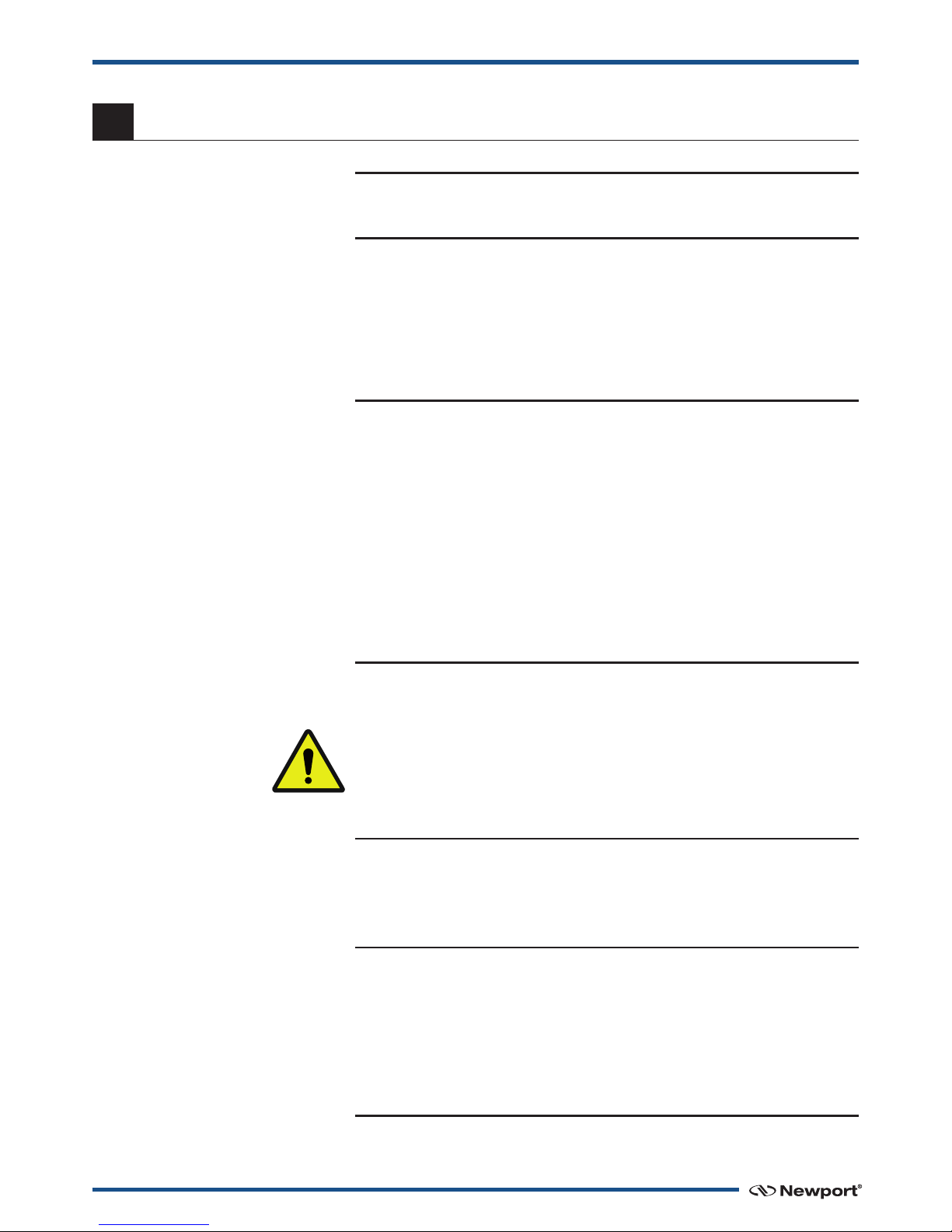
5.4 M CABLE-3 Cable
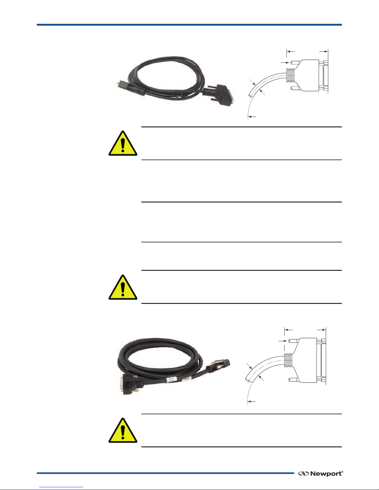
5.5 MCAB-3 Cable
CABLE
CONNECTOR STAGE
BENDING
STATIC CABLE: ≥.94 (24)
CABLE IN MOTION: ≥2.76 (70)
LOCKING
KNOBS
2.24 (57)
DISCONNECTED
ø.24
(6)
SUB-D15 CONNECTOR SHOWN
DIMENSIONS IN INCHES (AND MILLIMETERS)
WAR N IN G
Th s cable s sh elded correctly. For a correct operat on, make sure to
lock connectors (ground cont nu ty prov ded by the cable).
For a lications where the standard 3-meter cable (MSCABLE-3) included
with your stage is not adequate, New ort offers a 10-m longer length cable
(MSCABLE-10) designed to ensure the integrity of your ositioning
a lication.
REMARK
The cross sect on of the MSCAB-10 cable s d fferent from the one of the
MSCABLE-3 cable to allow a longer length. The MSCAB-10 cable has the
same mechan cal propert es as the MCAB-10 cable.
These cables are s ecially shielded and terminated with New ort’s
standard SUB-D15 and SUB-D25 connectors.
WAR N IN G
Keep the motor cables at a safe d stance from other electr cal cables n
your env ronment to avo d potent al cross talk.
CABLE
CONNECTOR STAGE
LOCKING
KNOBS
BENDING
STATIC CABLE: ≥1.50 (38)
CABLE IN MOTION: ≥3.78 (96)
2.28 (58)
DISCONNECTED
ø.39
(10)
SUB-D25 CONNECTOR SHOWN
DIMENSIONS IN INCHES (AND MILLIMETERS)
WAR N IN G
This cable is shielded correctly. For a correct operation, ma e sure to
loc connectors (ground continuity provided by the cable).
F
Table of contents
Other Newport Industrial Equipment manuals

Newport
Newport TSP Series User manual

Newport
Newport GTS-V Series User manual

Newport
Newport UTM Series User manual

Newport
Newport GTS30V User manual

Newport
Newport RV User manual

Newport
Newport PM 500 Installation manual

Newport
Newport ORIEL Instruments Cornerstone 260 User manual

Newport
Newport New Focus 8892 User manual

Newport
Newport IDL165-LM Series User manual
Popular Industrial Equipment manuals by other brands

PR electronics
PR electronics 6185 product manual

Reflex
Reflex longtherm Montage, installation

Emerson
Emerson Fisher ENVIRO-SEAL instruction manual

ALFRA
ALFRA AMTE250 Operation manual

Labelmate
Labelmate PM-300-CS-STEP Original user manual

Siemens
Siemens Flender KMP Series Assembly and operating instructions


