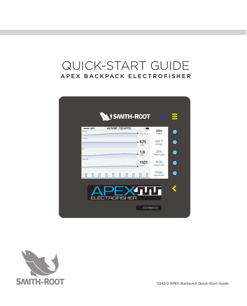
Smith-Root APEX BACKPACK User manual

11808.00 MANUAL APEX BACKPACK USER GUIDE
USER'S GUIDE
APEX BACKPACK

Items manufactured by companies other than Smith-Root carry the original manufacturer’s warranty.
Please contact product manufacturer for return instructions.
All Smith-Root, Inc. manufactured products are covered by a one year warranty.
Credit & Refund Policy: Customers returning equipment, in new condition, will be given credit five days
from the date of the return. A return authorization must accompany returns. Valid equipment returns
include, but are not limited to, ordering incorrect equipment, funding deficits, and defective equipment
returned for reimbursement. All returns are subject to a restocking fee and applicable shipping charges.
The restocking fee is figured at 10% of the purchase price but not less than $20.00. Customers receiving
equipment in damaged condition will be referred to the shipping company for insurance reimbursement.
11808.00 MANUAL APEX BACKPACK USER GUIDE - ©2021 Smith-Root, Inc.
CONTENTS
INTRODUCTION ........................................................................ 4
OVERVIEW ..................................................................................5
• APEX CONTROLS AND FEATURES .......................................................... 5
• USER INTERFACE OVERVIEW................................................................... 6
• GRAPHICAL USER INTERFACE (GUI) ...................................................... 6
• MAIN DISPLAY ............................................................................................... 7
• MENU PAGE (1/2) .......................................................................................... 8
• MENU PAGE (2/2) ......................................................................................... 9
BATTERY COMPARTMENT ....................................................10
• BATTERY CONNECTOR ............................................................................. 10
• ANODE AND CATHODE CONNECTORS................................................ 10
• CONTROL CONNECTOR..............................................................................11
SAFETY FEATURES..................................................................11
• EMERGENCY SHUTDOWN SWITCH .........................................................11
• QUICK RELEASE PACK FRAME .................................................................11
• FLASHING RED LIGHT ................................................................................12
• AUDIO ALARM..............................................................................................12
• ANODE SWITCH ...........................................................................................13
• TILT SWITCH..................................................................................................13
• IMMERSION SENSOR ..................................................................................13
• ANODE OUT OF WATER ............................................................................13
• ELECTRONIC CIRCUIT BREAKER ............................................................13
BATTERY COMPARTMENT INTERLOCK SWITCHES .......14
FUSIBLE LINKS.........................................................................14
TEMPERATURE SENSORS .....................................................14
FAULT CONDITIONS ............................................................... 15
• PEAK CURRENT OVERLOAD ....................................................................15
• OUTPUT IGBT FAILURE ..............................................................................15
• AVERAGE CURRENT OVERLOAD ............................................................15
• INVERTER OVERLOAD ...............................................................................15
• LOW BATTERY FAULT.................................................................................15
• BATTERY CURRENT TOO LOW ................................................................15
SETUP AND OPERATION.......................................................16
• BASIC SETUP ................................................................................................16
• RECOMMENDED ADJUSTMENTS .............................................................18
• USING RECALLED WAVEFORMS FOR SETUP ......................................19

3
APEX BACKPACK
www.smith-root.com
WARNING: LIVE ELECTRICAL EQUIPMENT WHEN ENERGIZED. DIRECT
CONTACT WITH EQUIPMENT MAY CAUSE ELECTRIC SHOCK OR BURN.
Appropriate personal protective equipment is required at all times. Using
this equipment in a manner not advised in the instruction manual could result
in injury, death, or damage to the unit. Users should notify bystanders of the
equipment’s use and function before and during operation. If conditions become
unsafe, cease using the equipment immediately.
CUSTOM SETUP PROCEDURE.............................................20
• USER-SELECTED SETTINGS.................................................................... 20
• TIMER SETTINGS........................................................................................ 20
• VOLTAGE ADJUSTMENT........................................................................... 20
• DUTY CYCLE ADJUSTMENT......................................................................21
• FREQUENCY ADJUSTMENT ......................................................................21
• WAVEFORM SETTING ................................................................................22
• DUAL WAVEFORM......................................................................................22
USB FEATURES ....................................................................... 23
• DATA LOGGING ...........................................................................................23
• DOWNLOADING DATA...............................................................................23
• SOFTWARE UPDATES................................................................................23
SPECIFICATIONS .................................................................... 24
BATTERY CARE, MAINTENANCE ....................................... 28
• BATTERY MAINTENANCE.........................................................................26
• HOW TO CHARGE BATTERIES ................................................................26
• LED INDICATORS ........................................................................................26
• BATTERY TYPES..........................................................................................27
• BATTERY STORAGE ...................................................................................28
• BATTERY RATINGS AND LIFE..................................................................29
ELECTROFISHING SAFETY .................................................. 28
• PROPER EQUIPMENT.................................................................................32
• PROTECTIVE EQUIPMENT ........................................................................33
• PREVENTING ELECTRICAL SHOCK .......................................................34
• ELECTROFISHING OPERATION...............................................................35
• PACKFRAME QUICK RELEASE ................................................................36
APPENDIX ................................................................................ 37
• SUSPENSION SYSTEM................................................................................39
• SUSPENSION SYSTEM ADJUSTMENTS................................................. 40
• ELECTRODE RING MAINTENANCE .........................................................41
• ELECTRODE POLE TESTER......................................................................42
• CATHODE TESTER......................................................................................42
• BASIC ELECTROFISHING ILLUSTRATION.............................................43
• CARRY CASE................................................................................................43
• GLOSSARY OF ELECTROFISHING TERMS........................................... 44

4
USER’S GUIDE
2021
INTRODUCTION
THE APEX BACKPACK ELECTROFISHER
The Apex Backpack Electrofisher is an upgraded version of the LR-24
with many new features and improvements. Its design incorporates
many safety features to help protect both operating personnel and fish.
The user interface has been designed to make the Apex backpack easy
to use. Many new graphical features such as the intuitive history charts
of the voltage, current, and power, allow the user to assess the condition
of the backpack as well as the environment easily and efficiently.
An immersion sensor automatically turns the output off if the bottom of
the pack frame comes into contact with water.
The anode-out-of-water detector automatically turns off the output if
the anode ring is raised out of the water while the output is on.
Taking the time to familiarize yourself with these features will go a long
way towards learning how to use the Apex Backpack Electrofisher in the
most efficient manner.
Attention! Before getting started electrofishing, make sure you become
acquainted with the safety features of the Apex backpack as shown on
page 11 and the section on safe electrofishing practices and techniques
starting on page (31), as well as information on emergency quick release
on page (36).

5
APEX BACKPACK
www.smith-root.com
OVERVIEW
APEX CONTROLS AND FEATURES
Take the time to familiarize yourself with
the APEX’s features before beginning
electrofishing.
1. Emergency Shutdown Switch: The main
on/off switch. The switch must be rotated
90 degrees clockwise to turn on the unit.
Pushing down will turn it off.
2. Keypad/Display: The control pad and
display, showing settings and status
of the Apex and allows setting of the
parameters.
3. GPS Antenna: Allows the Apex to receive
GPS information.
4. Flashing Red Light: Flashes to indicate
that the output is on or to indicate a fault.
5. Battery Compartment Cover: Covers
battery and connectors. Must be in place
and its 3 latches fastened for unit to
function.
6. Audio Alarms: Sounds to indicate that the
unit is on and to indicate modes or faults.
7. Audio Alarms: indicate modes or faults.
8. USB Port: For downloading data and
updating software via thumb drive.
9. Pack Frame: Main connecting point for
the harness system. All components are
mounted on the pack frame.
10. Cathode Connector: A clamp-on strain
relief allows the cathode cable/rattail to
pass through slots on either side of the
battery cover.
11. Battery Connector: Connects Apex to a
lithium or lead acid battery.
12. Control Connector: Allows control of
output to electrode pole.
13. Anode Connector: A molded strain relief
allows the anode cable to pass through
slots on either side of the battery cover.
14. Immersion Sensor: This sensor will
shut the unit down should the Apex be
immersed in water.
1
2
4
5
6
7
8
9
10 11 12 13
14
3
Figure 1Figure 1
Figure 2
Figure 3

6
USER’S GUIDE
2021
USER INTERFACE OVERVIEW
The panel has seven keys that perform a variety of functions. The function of each key
is determined based on the page that is visible on the display.
GRAPHICAL USER INTERFACE (GUI)
The Apex Keypad (Fig. 4) is comprised of 7 buttons which are described as follow:
1. Menu Button. Pressing this button will take the user to the setting menu.
2.-6. Generic buttons used for various functions. The function of the button is dis-
played on the left side of the buttons on the display (see Figure 4).
7. Back button is used to traverse back to the main display.
0016603
ELECTROFISHER
1
7
2
3
4
5
6
Figure 4

7
APEX BACKPACK
www.smith-root.com
1. GPS Signal Strength- This icon indi-
cates the strength of the GPS signal
which is used for time synchronization
and location tracking for the data log-
ging application.
2. Battery Level Indicator- shows the
battery level.
3. % Load- Indicates how much output
power is being utilized compared to
the maximum.
4. Peak Voltage- Peak voltage while the
unit is running.
5. Peak Amps-Peak current amplitude.
Note that this is the peak current and
not the average current.
6. Peak Watts- The peak output power
when the unit is running. This value
may be much higher than the 400W
continuous level since it is the peak
power.
7. Timer- Elapsed time in seconds. This
value is incremented only when the
output is active.
8. Voltage- Voltage setpoint of the out-
put. To change this value, see Voltage
Adjustment on page 22.
9. Duty Cycle-Duty cycle setpoint of
the output waveform. To change this
value, see Duty Cycle Adjustment on
page 22.
10. Frequency- Setpoint for frequency of
the waveform. To change this value,
see Frequency Adjustment on page
23.
11. Waveform-Indicates the current wave-
form type. To make modification to the
waveform type, see Waveform Setting
on page 23.
12. A three-minute history of the param-
eters described in 3-6. This chart also
includes any alarms or faults that have
occurred during that time.
MAIN DISPLAY
Main display provides the user with an intuitive way to monitor Apex conditions.
1 2
37
8
9
10
11
4
5
6
Figure 5
12

8
USER’S GUIDE
2021
MENU PAGE (1/2)
Menu Page is accessed by pressing the MENU button from the main screen.
A. Quick Setup- To use this feature please see page 18.
B. Electrode Out of Water Alarm- Enable or disable the alarm for when the electrode
out of water is detected. See Anode Out of Water on page 14 for more detail.
C. Power Limit- this setting enables the user to select whether to sound an alarm
when average power setpoint is reached or to go into a foldback mode by reduc-
ing the output voltage.
D. Dual Channels- This setting enables/disables the dual waveform capability of Apex.
For more information, see Dual Waveform on page 24.
Figure 6

9
APEX BACKPACK
www.smith-root.com
MENU PAGE (2/2)
A. High Temperature Response- This setting allows the unit to either sound an alarm
or to go into foldback mode by reducing output voltage. See page 14, Tempera-
ture Settings, for more information.
B. Display Mode- Display can be either in Dark mode or Light mode.
C. Device Information – Selecting this option will display general information of the
unit.
Figure 7

10
USER’S GUIDE
2021
BATTERY COMPARTMENT
Opening the battery compartment allows
the user to install or change the battery, or
connect the anode, cathode, and control
circuit connectors (Figure 8). Remove the
battery compartment cover by flipping
the handles on the three cam-lock latches
out and turning them counterclockwise.
Make sure the latch on the bottom of the
cover is free, then pull out on the two side
latches and lift the battery compartment
cover away from the Apex.
When replacing the battery compartment
cover, adjust it so that it is on the inside of
the molded guides of the pack frame. The
cover must be correctly placed before the
Apex will operate.
Close the cover latches.
BATTERY CONNECTOR
The battery connector, located inside the
battery compartment, is a rectangular red
and black plastic connector on the end of
the input power cable (Figure 9). It mates
with an identical connector on the Apex
battery packs. This connector is color
coded and polarized to prevent accidental
reverse connections of the battery.
ANODE AND CATHODE CONNECTORS
The anode and cathode connectors are
black plastic circular 2-pin connectors
located on the bulkhead between the
battery compartment and the electronics
compartment (Figure 10). Access to
these connectors is gained by removing
the battery compartment cover. The
connectors are identical and allow the use
of a trailing cathode cable or a cathode
pole for greater control over placement
of the output electric field. Both pins in
these connectors are live when the Apex
is on. These connectors are polarized, 1/4
turn, locking connectors
CONTROL CONNECTOR
The control connector is a smaller
4-pin version of the anode and cathode
connectors (Figure 10). It is also polarized,
and the smaller size prevents incorrect
connections. The Apex utilizes a low
voltage control circuit for added safety.
BATTERY COMPARTMENT AND CONNECTIONS
Figure 8
Use Only Smith-Root, Inc. Batteries With T his Unit.
Install Batteries As Sh own Below.
Battery
Heavy-Duty Standard
#6682 #6681
Lithium Iron
Phosphate
#10765
Figure 9
Figure 10

11
APEX BACKPACK
www.smith-root.com
EMERGENCY SHUTDOWN SWITCH
The large red mushroom switch located on the
top of the APEX is the Emergency Shutdown
Switch (Figure 11). To turn the power on, the
user must rotate the switch 90 degrees in the
direction of the arrows (clockwise). Since the
switch knob must be rotated, it helps to prevent
accidentally powering up the APEX. Pushing the
red mushroom knob down until it latches will
immediately turn the unit off.
QUICK RELEASE PACK FRAME
The APEX has an integrated quick release pack
frame (Figure 12). Just press the latch tabs
on the waist belt and shoulder straps and the
entire APEX falls away. See page 36 for more
information. Figure 11
Figure 12
A
B
B
B
A. Chest strap: remove
before entering water.
B. Quick release buckles
CAUTION: Always unlatch the chest strap
of the pack before entering or crossing water.
If left latched, this strap may prevent the user
from quickly removing the APEX in the event of
an emergency, such as falling into deep water.
ATTENTION! Use of the Apex Electrofisher outside the recommended operating
conditions specified by the manufacturer may result in impairment of the safety
features; hence creating unsafe conditions.
SAFETY FEATURES
Safety Dos and Don’ts
Dos:
• Always be sure that all personnel are clear of
the electrodes before turning on the power.
• Know how to administer first aid treatment
for electrical shock.
• Wear flotation devices
• Have electrical circuits checked only by
qualified technicians.
• Disconnect the power supply when the
electrofisher is not in use.
Don’ts:
• Do not electrofish alone.
• Do not continue to electrofish if boots or
gloves get wet inside.
• Do not operate an electrofisher with any
prior heart ailments.
• Do not electrofish when tired.

12
USER’S GUIDE
2021
FLASHING RED LIGHT
Bright long life LED lamps flash whenever
the APEX is turned on and output is active
(Figure 13).
AUDIO ALARM
The audio output alarm indicates four
different APEX operating conditions and is
composed of two tone-emitting units: one
high pitched and the other low pitched.
1. Presence of high voltage in the water:
Whenever the anode and cathode are
in the water and the output is active,
there will be an audible tone emitted
by the alarm.
2. Average Power Output Level: The
Audio Alarms emit pulsed tones to
indicate average power output level:
Average Power Output Level
Watts Audio Tone in Secs.
0 to 99.9 1 pulse per second
100 to 199.9 2 pulses per second
200 to 299.9 3 pulses per second
300 to 400 4 pulses per second
3. Power Limit Mode: When the APEX
output power reaches the user set
power limit, the audio tone alternates
between the high and low pitch at the
rates specified above.
4. Dual Output Mode: In this mode, the
APEX can operate with a primary or
secondary user-specified voltage/
waveform combination. The selection
between the two combinations is
accomplished by rapidly double
pressing the anode pole switch.
The primary voltage/waveform is
assigned to the high-pitched tone and
the secondary voltage/waveform is
assigned to the low-pitched tone.
ANODE SWITCH
A magnetic reed switch is used for the
anode pole switch. This switch has direct
shutdown control of the high voltage
output safety relay inside the APEX.
Releasing the flapper for the switch turns
the switch off (Figure 14).
TILT SWITCH
The tilt switch automatically turns off the
output of the APEX if the LR-24 is tipped
too far from vertical in any direction. The
maximum forward tilt is 50˚, backward tilt
is 40˚, and side tilt is 45˚, all from vertical
(see Figure 15). If tilted beyond these
limits, an error message is displayed. This
condition is reset by moving to a more
vertical position and releasing and pressing
the anode pole switch.
Figure 13
ON
OFF
Figure 14

13
APEX BACKPACK
www.smith-root.com
IMMERSION SENSOR
If the lower end of the APEX comes
into contact with the water, the output
is automatically shut off and an error
message is displayed. This condition is
reset by moving the APEX case out of
contact with the water and releasing pole
switch and pressing it again. Note that if
the battery compartment has filled with
water, it must be drained and completely
dried before resetting the unit.
Figure 16: Detail showing immersion sensor
ANODE OUT OF WATER
This feature disables the output of the
APEX and displays an error message
whenever the anode pole switch is
depressed and less than 30 milliamps
(mA) of current is flowing between the
anode and cathode. To restart the unit,
place the electrode in the water and press
the anode pole switch. For working in
very shallow water, this feature can be
turned off using the System Menu (see
Figure 17).
4040°°
5050°°
Figure 15
Figure 17
NOTE: This function is NOT reactivated
automatically when power is turned off
and back on.

14
USER’S GUIDE
2021
BATTERY COMPARTMENT INTERLOCK
SWITCHES
The cover of the battery compartment
contains an interlock mechanism (Fig.
18, A) that automatically turns off power
to the unit if the cover is opened. When
replacing the battery compartment cover,
adjust it so that it is on the inside of the
molded guides (Fig. 19, B) of the pack
frame. The cover must be correctly placed
before the APEX can operate.
FUSIBLE LINKS
The battery pack of the APEX incorporates
a fusible link to protect the batteries from
excessively high currents. In the event this
fusible link blows out, it must be replaced
with the same size and type as the original
link to provide protection for the battery
pack and the wiring.
If your APEX is working hard on hot
days, it may overheat and shut down.
If the air temperature in the box reaches
160F, or if the heat sink reaches 200F,
an over-temperature error message will
be displayed, and the output will be
disabled until the unit cools down.
When using any of the pulsed outputs,
the unit can reduce the output voltage
automatically based on its internal
temperature when using Thermal Power
Foldback Mode. This has the effect of
reducing the power level of the unit
and therefore the heat being produced
inside the system.
This can allow the unit to continue to
work instead of waiting for it to cool
down again. This power reduction
does not begin until the Apex is near
the point of thermal overload, so under
most conditions it does not affect the
output at all.
When enabled and the temperature
of the unit reaches the trip point,
both audio alarms will begin to beep
simultaneously, and the Thermal Limit
display will show applied voltage based
on the internal temperature of the unit.
Figure 18 Detail showing relative locations of interlock
switch inside control box and magnet inside of lid.
Figure 19 Detail showing molded guides on pack
frame. Lid must be aligned correctly and latched for
unit to operate.
A
B
WARNING: Replacement of this link
by anyone other than Smith-Root, Inc.
will void the warranty of the entire
electrofishing system.
TEMPERATURE SENSORS
There are internal temperature
sensors which can shut the APEX
down if excessive temperatures are
detected. If the unit is shut down due
to high temperature, an error message is
displayed for as long as the temperature
is above safe limits. After the APEX has
cooled, the error message is cleared, and
full operation is automatically restored.
The Thermal Foldback Mode can help
decrease the chance of shutdown due
to excessive temperature. Thermal
Foldback can be enabled from the Menu
screen (See Page 9, High Temperature
Response).

15
APEX BACKPACK
www.smith-root.com
FAULT CONDITIONS
PEAK CURRENT OVERLOAD
If the peak output current exceeds 40
amps, the output is disabled, and an
error message is displayed. This is usually
caused by a short circuit between the
anode and the cathode. The unit can be
reset by releasing the switch on the anode
pole and pressing it again.
OUTPUT IGBT FAILURE
If there is an output switch (IGBT) Failure,
the unit’s output is shut off and an error
message is displayed.
The criteria for an Output Switch Fault is
that output voltage has been detected
when there should be none. For example,
if the anode pole switch is not activated,
there should be no output from the unit.
If, however, output is detected, then an
Output Switch Fault exists, and the Apex’s
output will be disabled.
Note: The Apex must then be sent back to
Smith-Root for repair. Do not attempt to
use the unit if this message appears, as a
safety hazard may exist, and further use
may cause more damage to the Apex.
AVERAGE CURRENT OVERLOAD
The input and output current of the Apex
are constantly monitored while in use. If
these currents become excessive, the
unit will shut down its output to prevent
damage to its circuits. Releasing the
pole switch and selecting a lower output
voltage or lower duty cycle waveform
should clear this fault.
INVERTER OVERLOAD
If the Output Voltage is set too high for
the water conductivity and the electrode
spacing, the Apex will turn off its output
and display and error message. The error
message will suggest a more appropriate
voltage for the present conditions. If this
error is caused by a mistake, for example,
temporarily having the Anode and
Cathode too close together, acknowledge
the error message by releasing the pole
switch.
If the error message shows up again in a
short time, acknowledge the message and
reduce settings to the suggested voltage
before proceeding. This message occurs
when the output voltage drops more
than 30% below the voltage the user has
set on the Apex. This occurs when the
water conductivity or electrode spacing
(or both) are such that more power is
being required from the unit than it can
supply. Note the average and peak power
readings on the display. While the average
power may be quite low, the peak power
will be far above the 400 watts the unit
can supply on a continuous basis.
LOW BATTERY FAULT
When the battery is less than 20V, the
Apex will shut down its output and display
the Low Battery message. Turn off the
power and replace the battery with one
fully charged to clear this fault.
BATTERY CURRENT TOO LOW
If the input current measuring circuit
does not measure any current, this error
message will appear and the power to the
unit will have to be turned off and back on
to clear the message. This test is included
to detect problems in the input current
sensing circuit. If this error message
appears again, the unit will have to be sent
to Smith-Root for repairs.
NOTE: Make sure the electrode ring is
clean and shiny. A cloudy dull-gray
electrode ring will reduce catch-
per-unit effort and will increase the
fish injury rate (see Electrode Ring
Maintenance, page 42). Initial setup
of voltage, frequency, duty cycle, and
waveform should be done outside of
the sample area.

16
USER’S GUIDE
2021
SETUP AND OPERATION
BASIC SETUP OF THE APEX:
1. Make sure the power switch on the
top of the Apex is in the OFF position
(pressed DOWN).
2. Attach the anode and cathode to their
output connectors. Attach the smaller
connector on the anode cable to the
control connector of the Apex.
3. Put the Apex on. Be sure to know the
location of the quick release buckles
for the backpack and unlatch the
chest strap before entering or crossing
the water (refer to Appendix E: Pack
Adjustments for further instructions).
4. Check with each crew member to be
sure they know you are ready to turn
on the power.
5. Turn on the power. Do not press the
anode switch. Check the operation
of the tilt switch by bending forward
until the tilt switch activates, (about 55
degrees) and the tilt message appears
on the display. Straighten up and the
status display should return. If the
tilt message does not appear, do not
use the unit. Send it to Smith-Root for
repair.
6. Place a dampened cloth on the
immersion sensor contacts located on
the lower corner of the Apex, under
the battery compartment. The display
should show the immersion warning.
When the cloth is removed, the display
should return to the status screen.
If the immersion message does not
appear when touched with a wet cloth,
do not use the unit; send it to Smith-
Root for repair.
7. Press the Menu Key
8. Next, press the key corresponding to
“Quick Setup”.
9. Make sure the cathode cable is behind
you and then place the anode ring in
the water in front of you.
CathodeCathode
connectorconnector
AnodeAnode
connectorconnector
ControlControl
connectorconnector
Figure 20
Figure 21
Figure 22

17
APEX BACKPACK
www.smith-root.com
10. Press the switch on the anode pole
and hold the flapper down. The unit
will analyze the conditions and set up
the waveform accordingly. It should
take a few seconds of running followed
by three beeps of the audio tone
indicating the completion of analysis.
11. The Apex is now set up.
12. The Quick Setup mode provides
conservative settings that may need to
be adjusted for optimal results.
Figure 23
Figure 24

18
USER’S GUIDE
2021
RECOMMENDED ADJUSTMENTS
Quick Setup adjusts the Apex to produce
30 Hz, 12% duty cycle at 26 watts average
output power. This is only a suggested
starting point, and any or all the output
settings may be changed by the user at
any time. Duty cycle and frequency can
have a huge impact on taxis. In general,
lower frequencies are safer for fish than
higher frequencies. If you are not getting
any response from fish, change the Apex
settings as follows:
A. Increase the voltage in 50-volt
increments. Stop increasing voltage
when you begin getting a forced
response (twitch), from the fish when
pressing the anode pole switch.
B. If fish are not showing taxis, lower
the voltage to the original level and
increase the duty cycle by 5% and
try again. If necessary, repeat step
“a” from above until you elicit taxis
in the fish. If the voltage is increased
to maximum and taxis is still not
achieved, reduced the voltage and
increase duty cycle by 5% again. If
no response after increasing duty
cycle, lower all settings and proceed
to step “c”.
C. Increase the frequency by 5Hz and
try again. If necessary, go back to
step “a” before increasing frequency
again.
Observe the collected fish closely. In
general, if it takes more than 5 seconds
for a fish to recover, it may have been
shocked too much. If it takes more than
15 seconds for a fish to recover, it was
shocked too much; reduce the frequency,
duty cycle, and/or output voltage of the
unit.
Taxis and Tetany
There may be some confusion between taxis
and tetany. Taxis is an induced swimming
action. The nerves have time to repolarize,
and the muscles have time to relax between
output pulses of the electrofisher.
Tetany is locking up the muscles. The fish is
stiff and there may be some slight quivering
in the fins. While the fish may move toward
the anode (positive electrode), this is not
taxis. The output of the electrofisher should
be reduced.
“Rolling fish over” should be avoided when
electrofishing. With settings high enough to
quickly knock fish out, injury rate is higher
than it should be. Ideally, fish will swim into
the net while following the anode. Recovery
time should be quick, and the fish should be
able to swim normally immediately upon being
placed in the holding tank. IT should not take
more than 5 seconds for a fish to recover after
being placed in the holding tank. If it takes 15
seconds or more for fish to recover after being
placed in the tank. Then reduce the output
settings of the electrofisher.
Before Electrofishing
The most experienced members of the
electrofishing crew should be doing the
netting. They know what to expect, what to
look for, and where to look. The next most
experienced member of the crew should be
running the Apex, looking for likely habitat.
The next most experienced member of the
crew should be taking care of the recovery
tank. The tank should be kept out of the sun,
water temperature checked regularly, and
oxygen levels in the tank checked if the fish
are held very long before being worked up and
released.
Never electrofish with unauthorized people
standing on the bank. Under certain
conditions, the field of the electrofisher can
travel long distances. Things to look for
include sheet piling, metal culverts, buried
pipes, suction lines for irrigation, etc.

19
APEX BACKPACK
www.smith-root.com
USING RECALLED WAVEFORMS FOR SETUP
1. From the Main display, Press the
button corresponding to the waveform
setup.
2. Press the button corresponding to
“Favorites”.
3. The next window displays all the
saved waveforms. You may select
any of the waveforms by pressing the
corresponding button.
4. You are ready to begin electrofishing.
5. Observe the reactions of the fish.
It may be necessary to adjust the
settings. Duty cycle and frequency
can have a huge impact on taxis. In
general, lower frequencies are safer
for fish than higher frequencies. See
adjustments a, b, and c on page 18
Figure 25
Figure 26
Figure 27

20
USER’S GUIDE
2021
CUSTOM SETUP PROCEDURE
USER-SELECTED SETTINGS
This procedure allows operators to select
various settings for electrofishing. The
proper procedure involves selecting
the waveform or pulse type, voltage,
frequency, duty cycle, and power limit.
TIMER SETTINGS
A. The timer counts the number of
seconds the flapper was activated
since it was reset. To reset the timer,
Press the TIMER button, then press
RESET. Once complete, press the
BACK button to return to the home
screen.
A. An alarm can be set at 60 second
intervals to inform the user that a
defined amount of effort has elapsed.
A reminder alarm will subsequently
activate every 60 seconds of effort
beyond the alarm. Therefore, it can
be helpful to set the alarm for 60
seconds less than the intended effort
as a method of warning the user of
the upcoming end of effort. To set
the Alarm, press the TIMER button,
then press ALARM and use arrows to
increase or decrease the number of
seconds. Once complete, press BACK
button to return to home screen. A
tonal alarm will activate once the
noted amount of electrofishing
effort elapses. A reminder alarm will
continue to occur every 60 seconds
after the alarm is triggered until the
timer is reset.
VOLTAGE ADJUSTMENT
The voltage setting corresponds to the
amplitude of the voltage applied in
the water. The voltage should be set
according to environmental conditions,
especially ambient water conductivity.
To modify voltage, press the VOLTAGE
button, then use the arrows to increase or
decrease values. Once complete, press
the BACK button to return to the home
screen.
A. 500-1,200 Volts – High voltage is used
in very low ambient conductivity water.
Additionally, higher voltages are often
useful in deep and wide pools. Battery
life is significantly reduced when using
high voltage.
B. 150-500 Volts – Moderate voltage is
typically used in moderate ambient
conductivity waters.
C. 50-150 Volts – Low voltage is typically
used in high conductivity water.
Additionally, lower voltage is often
useful in shallower pools.
Figure 28: Voltage Adjustment
Table of contents
Other Smith-Root Analytical Instrument manuals
Popular Analytical Instrument manuals by other brands

Bühler technologies
Bühler technologies GAS 222.31 Ex2 Installation and operation instruction

Sealey
Sealey Professional TOOLS AUTO SERVICE Series instructions

Teslong
Teslong WF200 user manual

XTline
XTline XT130512 Original instruction manual

Leuze electronic
Leuze electronic ODS 10 operating instructions

viZaar
viZaar VUCAM Series operating instructions