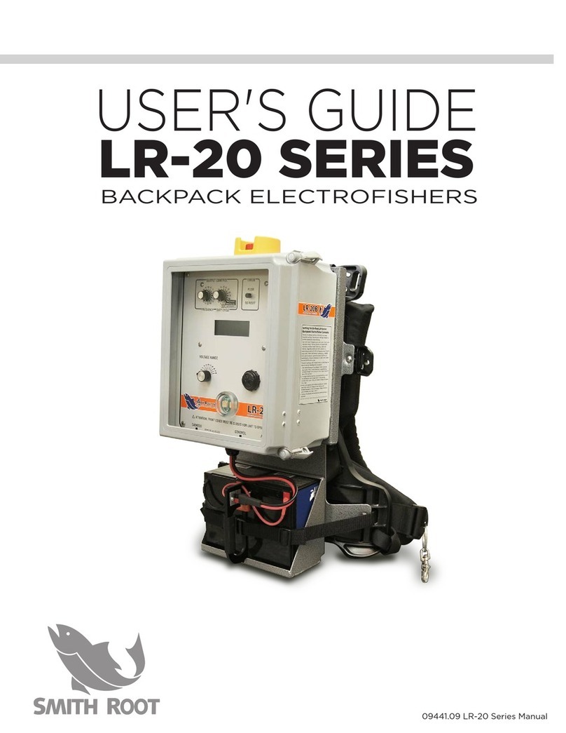
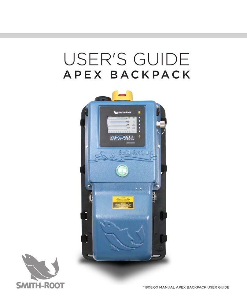
Smith-Root Apex User manual

11243.0 APEX Backpack Quick-Start Guide
QUICK-START GUIDE
APEX BACKPACK ELECTROFISHER
0016603
ELECTROFISHER

Items manufactured by companies other than Smith-Root carry the original
manufacturer’s warranty. Please contact product manufacturer for return
instructions.
All Smith-Root, Inc. manufactured products are covered by a one year warranty.
Credit & Refund Policy: Customers returning equipment, in new condition, will be given credit
five days from the date of the return. A return authorization must accompany returns. Valid
equipment returns include, but are not limited to, ordering incorrect equipment, funding deficits,
and defective equipment returned for reimbursement. All returns are subject to a restocking fee
and applicable shipping charges. The restocking fee is figured at 10% of the purchase price but
not less than $20.00. Customers receiving equipment in damaged condition will be referred to the
shipping company for insurance reimbursement.
11243.0 APEX Backpack Quick-Start Guide - ©2018 Smith-Root, Inc.
CONTENTS
Controls and Features .................... 3
External Components ..................... 4
i. Electrodes
ii. Battery
iii. Battery Compartment Lid
Powering up and down................... 5
i. Power Button
Electrical Settings............................ 6
i. Waveform
ii. Frequency
iii. Duty Cycle
iv. Voltage
Favorites ............................................ 8
i. Saving Electrical Inputs
ii. Recalling Electrical Inputs
Effort................................................... 8
i. Timer/Alarm
In Field Help...................................... 9
i. Light Bulbs
ii. Diagnostic Screen
Menu ................................................... 9
i. Quick Setup
ii. Electrode Out of Water Alarm
iii. Power Limit
iv. Power Limit Response
v. Dual Channels
vi. High Temperature Response
vii. Device Information
Input and Output Data Storage...12
i. Data Storage
Safety.................................................13
i. Sound
ii. Immersion Sensor
iii. Tilt Sensor
iv. LED Light
v. Quick Release Harness
vi. Non-Conductive Housing & Connectors
vii. Customized Adjustable Harness
viii. Electrode Out Of Water Alarm

3
APEX BACKPACK ELECTROFISHER
www.smith-root.com
1. EMERGENCY SHUTDOWN SWITCH
The main on/off switch. The switch must
be rotated 90 degrees clockwise to turn
on the unit. Pushing down will turn it off.
2. KEYPAD/ DISPLAY
The control pad and display, showing
settings and status of APEX and allowing
the setting of parameters.
3. GPS ANTENNA
Allows APEX to send and receive GPS
information.
4. FLASHING RED LIGHT
Flashes to indicate that the output is on
or to flash to indicate a fault.
5. BATTERY COMPARTMENT COVER
Covers battery and connectors. Must be
in place and its 3 latches fastened for unit
to function.
6. & 7. AUDIO ALARMS (LEFT, RIGHT)
Sounds to indicate that the unit is on and
to indicate modes or faults.
8. USB PORT
For downloading data and updating soft-
ware via thumb drive.
9. PACK FRAME
Main connecting point for the harness
system. All components are mounted on
the packframe.
10.CATHODE CONNECTOR
A molded strain relief allows the cathode
cable/rattail to pass through slots on
either side of the battery cover.
11. BATTERY CONNECTOR
Connects APEX to a lithium or lead acid
battery.
12. CONTROL CONNECTOR
Allows control of output to electrode
pole.
13. ANODE CONNECTOR
A molded strain relief allows the anode
cable to pass through slots on either
side of the battery cover.
14. IMMERSION SENSOR
This sensor will shut the unit down
should the APEX be immersed in water.
APEX CONTROLS AND FEATURES
Take the time to familiarize yourself with the APEX’s features before beginning electrofishing.
1
8
6
7
3
2
49
5
10 11 12 13
14

4
QUICK-START GUIDE
2018
APEX Backpack Electrofisher Quick-Start Guide
1. External Components
i. Electrodes – Electrically positive
anode and negative cathode of the
electric system.
a. Anode – Attach metal ring to end
of anode pole with 7/16” wrench.
Attach the anode and control con-
nectors to the appropriate recep-
tacles inside the battery compart-
ment. Align and position anode
pole connector’s internal tab with
notch on Apex anode connector’s
notch to mate into position. A half
turn is all that is needed for attach-
ment once properly aligned.
b. Cathode – Attach the cathode connector to the appropriate
receptacle inside the battery compartment. Align and position
cathode connector’s internal tab with notch on Apex cathode
connector’s notch to mate into position. A half turn is all that is
needed for attachment once properly aligned. An anode pole
can also be used as a cathode to increase control over electric
field size and direction. If an anode pole is used, the control con-
nector will not be attached on the cathode pole and the flapper
on the cathode pole will be inactive.
WARNING! LIVE ELECTRICAL EQUIPMENT WHEN
ENERGIZED. DIRECT CONTACT WITH EQUIPMENT MAY
CAUSE ELECTRIC SHOCK OR BURN. Appropriate personal
protective equipment is required as all times. Using this equipment
in a manner not advised in the instruction manual, quick start guide,
tutorial video(s) or otherwise could result in injury, death, or damage
to the unit. Users should notify bystanders of the equipment’s use
and function before and during operation. If conditions become
unsafe, cease using the equipment immediately.
Before electrofishing, it is strongly advised to have and wear non-
breathable chest waders, electrically rated lineman gloves, and
proper footwear.
View showing orientation of
Anode or Cathode connector pins,
key-way notch in bottom.

5
APEX BACKPACK ELECTROFISHER
www.smith-root.com
ii. Battery – Supplies power to the electrofisher
a. Lead Acid – Attach the red and
black connectors from the back-
pack to the red and black connec-
tors on the battery.
b. Lithium – Attach the lithium bat-
tery’s multicolored 6 pin adapter to
the battery then attach the red and
black connectors from the back-
pack to the red and black connec-
tors on the adapter.
c. Strap – Properly attach and tighten
the battery strap to secure the bat-
tery in place during use.
d. Low Battery – The APEX will display a low battery warning when
the battery voltage is below 21.0 volts and electrical output will
cease when the input battery voltage is below 20.0 volts.
iii. Battery compartment lid – Covers and protects battery and con-
nectors.
a. Strain relief - Properly align the strain relief devices on the anode
and cathode cords with the battery compartment lid openings to
prevent strain on connectors.
b. Latches – To loosen the three latches, flip open latches and twist.
To tighten the three latches, twist and flip closed.
c. Safety magnet – A safety magnet is
attached to the inside of the battery
compartment lid. The backpack will
not turn on if this magnet and bat-
ter cover are not properly aligned
and in place.
2. Powering up and down
i. Power button – Red button on top
of backpack with yellow protective
shroud.
a. Double Check – Ensure that battery
and electrodes are properly con-
View of multi-colored lithium
battery adapter connector.
Pushbutton on top of Apex.

6
QUICK-START GUIDE
2018
nected, battery compartment lid is properly aligned and in place,
that backpack is upright, immersion sensor is dry and not im-
mersed, flapper switch on anode pole is not pressed, and no one
is in contact with electrodes prior to turning on the backpack.
b. Turn on - Twist and lift the red button to activate the backpack. A
short tone will emit from the backpack then the red light will acti-
vate for duration of the startup time (about 15-20 seconds).
c. Turn off – Push down on the red button.
3. Electrical Settings
i. Waveform – Determines the shape of
the electrical output. Press WAVE-
FORM button and select a waveform.
Press BACK button to return to home
screen. Press FAVORITES button to
store and recall settings. Once com-
plete, press BACK button to return to
home screen.
a. Direct Current (DC) – Continuous,
uninterrupted current, flows from
backpack between anode and cathode. This method is favored
for use with endangered and threatened species because it min-
imizes the incidence of potential injury. However, capture effi-
ciency is low and battery usage is high.
b. Pulsed Direct Current (PDC) – Current is pulsed at a given fre-
quency and duty cycle. This is the most commonly used elec-
trofishing waveform because of its balance of minimizing inci-
dence of injury to fish while increasing capture efficiency and
lengthening the use of the battery.
c. Burst of Pulses – Current is pulsed in packets of bursts with
defined gaps of electrical output between bursts. This wave-
form is commonly used with Dual Output mode activated while
catching fish in heavy cover or removing juvenile lamprey from
sediments.
ii. Frequency – Determines the rate of electrical pulsing. To modify
frequency, press FREQUENCY button, then use arrows to increase
and decrease values. Once complete, press BACK button to return
to home screen.
Screenshot: Waveform types

7
APEX BACKPACK ELECTROFISHER
www.smith-root.com
a. 7.5 – 15 Hertz – Low frequency is
commonly used with Pulsed Direct
Current Waveform to capture cat-
fish and other electrically sensitive
bottom dwelling fish. Fish are of-
ten active, requiring active netting.
b. 30 Hertz – Moderate frequency is
commonly used for more fragile
species with increased vertebral
count and minimized scales.
c. 60 hertz – Higher frequency is
commonly used for more robust
species with decreased vertebral
count and thicker scaling.
iii. Duty Cycle – Determines the percent-
age of time that the backpack is ap-
plying power every cycle. To modify
Duty Cycle, press DUTY CYCLE but-
ton, then use arrows to increase and decrease values. Once com-
plete, press BACK button to return to home screen.
a. 12-15% - A minimal duty percentage that maintains very short
widths for each electrical pulse. Similar to low frequency, this is
commonly used for more fragile species with increased vertebral
count and minimized scales. It also helps conserve battery life.
b. 20-40% (~30%) – A duty percentage commonly used for more
robust species with decreased vertebral count and thicker scal-
ing. This longer duty cycle will decrease the battery life but will
generally increase capture efficiency.
iv. Voltage – Determines the amplitude
of the electrical potential. The voltage
should be set according to environ-
mental conditions, especially ambient
water conductivity. To modify voltage,
press VOLTAGE button, then use ar-
rows to increase and decrease values.
Once complete, press BACK button to
return to home screen.
Screenshot: Duty Cycle
Screenshot: Frequency
Screenshot: Voltage

8
QUICK-START GUIDE
2018
a. 500 – 1,200 Volts – High voltage is used in very low ambient con-
ductivity water. Additionally, higher voltages are often useful in
deep and wide pools. Battery life is significantly reduced when
using high voltage.
b. 150 – 500 Volts – Moderate voltage is typically used in moderate
ambient conductivity waters.
c. 50 – 150 Volts – Low voltage is typically used in high conductivity
water. Additionally, lower voltage is often useful in shallower pools.
4. Favorites
i. Saving Electrical Inputs – To save an
electrical input to the Favorites sec-
tion, press the WAVEFORM button on
the home screen, then press FAVOR-
ITES. Finally, press the + button to
save the active input settings.
ii. Recalling Electrical Inputs - To activate
an electrical input previously saved
in the Favorites section, press the
WAVEFORM button on the home screen, then press FAVORITES.
Finally, press the button associated with the previously saved input
settings of choice to active them.
5. Effort
i. Timer/Alarm
a. Timer – The timer counts the number of seconds the flapper
was activated since the timer was last reset. To reset the tim-
er, Press the TIMER button, then press RESET. Once complete,
press BACK button to return to home screen.
b. Alarm – An alarm can be set at 60 second intervals to inform
the user that a defined amount of effort has elapsed. A re-
minder alarm will subsequently activate every 60 seconds of
effort beyond the alarm. Therefore, it can be helpful to set the
alarm for 60 seconds less than the intended effort as a meth-
od of warning the user of the upcoming end of effort. To set
the Alarm, press the TIMER button, then press ALARM and use
arrows to increase and decrease the number of seconds. Once
complete, press BACK button to return to home screen. A ton-
Screenshot: Favorites

9
APEX BACKPACK ELECTROFISHER
www.smith-root.com
al alarm will activate once the noted amount of electrofishing
effort elapses. A reminder alarm will continue to occur every
60 seconds after the alarm is triggered until the timer is reset.
6. In Field Help
i. Light Bulbs – Light bulb icons can be accessed on the backpack for
further information on particular topics.
ii. Diagnostic Screen – A diagnostic screen can be found in the menu
that displays a multitude of input and output parameters along with
system information.
7. Menu
i. Quick Setup – Quick Setup will de-
termine a conservative voltage by
sampling the resistance of the elec-
tric circuit when the electrodes are
placed in the water. Therefore, it is
imperative that electrodes be sub-
merged in the water in a typical
position for your given sampling site.
Once standing in a typical electro-
fishing position, press and release
the pole switch. Observe the recommended voltage. Pressing and
releasing the pole switch will continue to offer voltage suggestions.
Sampling multiple times will give a sense of consistency of read-
ings. Note that a change in electrode placement will impact circuit
resistance, and will therefore impact recommended voltage. Wave-
form will always be set to Pulsed Direct Current, Frequency will
always be set to 30 Hertz, and Duty Cycle will always be set to 12%.
After running quick setup, the user may need to slightly increase
the voltage to increase capture efficiency.
ii. Electrode Out of Water Alarm – A safety mechanism that stops
electrical output when an electrode is removed from the water or
the circuit is broken.
a. Activated – If very high resistance is encountered because a con-
nector is loose, an aluminum anode pole that is corroded, or an
electrode is removed from the water, the backpack will stop the
output of electrical current. To reactivate, tighten connector or
Screenshot: Quick Setup

10
QUICK-START GUIDE
2018
place electrode back in water and press the anode pole flapper
once again.
b. Deactivated – While continuously holding down the anode pole
flapper switch, the backpack will immediately deliver electrical
current once the electrical circuit is completed. This is common-
ly used in shallow riffles areas where the circuit is frequently bro-
ken when bouncing the electrode from small pool to small pool.
iii. Power Limit – Allows the user to decrease to output power capaci-
ty of the backpack.
a. 400 Watts – The backpack will automatically default to 400
Watts upon startup. This is the maximum output the backpack
can sustain and is the setting to continue using to realize the full
capabilities of the backpack.
b. <400 Watts – Users can limit the output of the APEX backpack
to standardize use with alternative backpack electrofisher manu-
facturers. This restriction ensures that capture efficiency is main-
tained between equipment.
iv. Power Limit Response – Determines the response of the backpack
when the Power Limit is reached.
a. Alarm – Output power will cease and an alarm with indicate that
the power limit was reached.
b. Reduced Voltage and/or duty cycle – Output power will contin-
ue and the backpack will automatically reduce the voltage to
prevent the power limit from being exceeded. This is most often
used when operating at the extremes of the backpack’s environ-
mental capabilities (i.e. unusual ambient water conductivities).
v. Dual Channels – Allows the user to define and activate two differ-
ent electrical outputs by releasing and pressing the anode pole
flapper in less than one second.
a. Activated – A single electrical output is set on the main screen.
b. Deactivated – Two electrical outputs, a primary and a second-
ary, are set on the main screen. This is commonly used when a
sensitive setting is used in the primary output slot and a more
aggressive output is used in the secondary to allow fish to es-
cape heavy cover then be properly incapacitated. The primary

11
APEX BACKPACK ELECTROFISHER
www.smith-root.com
outputs are activated by pressing the anode pole flapper (high-
er pitched tone emits from backpack) and the secondary can
be activated by releasing and pressing the pole flapper (lower
pitched tone emits from backpack) in less than one second.
vi. High Temperature Response – Determines the response when the
temperature exceeds the limitations of the equipment. High inter-
nal backpack temperatures rarely occur, and are generally indica-
tive of hot air temperatures, direct sunlight, and high voltage and
duty cycle settings.
a. Alarm - Output power will cease and an alarm with indicate that
the temperature limit was reached. Place backpack in a cool
place to allow the equipment to reduce temperature.
b. Reduced Voltage – Output power will continue and the back-
pack will automatically reduce the voltage to prevent the power
limit from being exceeded. This is most often used when oper-
ating at the extremes of the backpack’s environmental capabili-
ties (i.e. unusual ambient water conductivities).
vii. Device Information – Displays information about the manufactur-
ing, service, and operation of the backpack electrofisher.
a. Reset – Resets the Apex Backpack to default settings.
b. Diagnostics – Displays information about the performance of the
backpack electrofisher.

12
QUICK-START GUIDE
2018
8. Input and Output Data Storage
i. Data Storage – The APEX stores
input and output data every sec-
ond that the anode pole switch is
activated.
a. Recording data – Hold down
the anode pole switch while
electrofishing and the APEX
automatically records data.
b. Viewing Data – The home
screen displays real time
electrical input values, peak
electrical output values, GPS
location (when signal is avail-
able), battery meter, timer/
alarm, and real-time graphs.
Real-time graphs actively
display the previous 3 min-
utes of peak output electrical
settings as well as all faults/
errors/warnings. Along the
bottom of the home screen
is a display of one second of
input variables in graphical
format that animates when
the anode pole switch is acti-
vated.
c. Downloading data – Unscrew
the dust and water cap from
the USB port on the side of
the backpack and insert a
USB flash drive. Follow on-
screen prompts to remove
USB flash drive. All stored
data on the backpack will
load onto the USB flash
drive as a .csv file that can
be opened in a spreadsheet
program (i.e. Microsoft Excel).
Place cap back on backpack
after transferring data.
Screenshot: Home Screen

13
APEX BACKPACK ELECTROFISHER
www.smith-root.com
Common sense and experimental data indicate that there is no
guarantee of complete safety with use of any electrical equipment. This
is largely due to variations in human skin resistance, and the threshold
at which individuals respond differently to electrical currents. As with all
electronic equipment, especially with any electrical device in or near water,
the Apex Electrofisher requires the operator to be aware of the danger of
electrical shock due to misuse.
Before electrofishing, it is strongly advised to have and wear non-breathable
chest waders, electrically rated lineman gloves, and proper footwear.
9. Safety
i. Sound – Two tonal alerts make a tone when the backpack is first
turned on, when an error/fault/warning occurs, and when the an-
ode pole switch is activated. Tonal rate is continuously related to
the average power being put into the water. A lower rate (~1 tone
per second) indicates lower power and a high rate (~4 tones per
second) indicates higher power. The volume can be controlled by
rotating the bezel on the tonal alert.
ii. Immersion sensor – An immersion sensor is located at the bottom
of the APEX pack frame. Output will cease when the sensor is im-
mersed. Do not alter or encase the immersion sensor.
iii. Tilt sensor – The backpack will cease electrical output if the back-
pack is tilted too far in any direction. Researchers often find that,
while electrofishing, bending at the knees rather than at the waist
provides increased balance and prevents the tilt sensor from un-
necessarily thinking the user has fallen over.
iv. LED light - Lights on the face of the APEX backpack activate when
the backpack is first turned on in sync with sound, when an error/
fault/warning occurs, and when the anode pole switch is activated.
In noisy situations, this safety feature proves valuable.
v. Quick Release Harness – Easy to release buckles on the harness
allow the wearer to quickly remove the backpack.
vi. Non-conductive housing and connectors – The non-conductive
housing and connectors provide increased safety because of their
resistance to conducting electricity.
vii. Customized adjustable harness – Adjust the pack frame harness to
fit you for the long day in the field.
viii. Electrode out of water alarm – Electrical output ceases and dis-
plays an error when an electrode is removed from the water, a
connector is improperly connected or loose, a corroded aluminum
anode ring or damaged electrode pole, or the electrical circuit is
broken for any other reason (i.e. internal circuitry issues).

info@smith-root.com
(360) 573-0202
Vancouver, WA USA
www.smith-root.com
S
i
n
c
e
1
9
6
4
Table of contents
Other Smith-Root Analytical Instrument manuals
