Smith FS351 Series Use and care manual

3A7832A
EN
Operation, Repair, Parts
SMITH FS351™
For removal of materials from flat horizontal concrete and asphalt surfaces. Not approved for
use in explosive atmospheres or hazardous (classified) locations. Gas/propane units not for
use indoors or in enclosed spaces. For professional use only.
Models 25P477/25R104 SMITH FS351 G DCS (High speed / Standard speed)
Models 25P478/25R105 SMITH FS351 P DCS (High speed / Standard speed)
Models 25P479/25R106 SMITH FS351 E DCS 480V (High speed / Standard speed)
Models 25P782/25R107 SMITH FS351 E DCS 380V (High speed / Standard speed)
Gas/Propane Maximum Working Pressure: 750 psi (52 bar, 5.2 MPa)
Electric Maximum Working Pressure: 1000 psi (69 bar, 6.9 MPa)
Important Safety Instructions
Read all warnings and instructions in this manual and in the Kohler engine manual before
using the equipment. Be familiar with the controls and the proper usage of the equipment.
Save these instructions.
Related Manuals:
62 590 13 - Kohler Owner’s Manual (Gas) 24 590 52- Kohler Owner’s Manual (Propane)
FS351 G DCS FS351 P DCS FS351 E DCS
(Drums and cutters sold separately)

Contents
23A7832A
Contents
Warnings . . . . . . . . . . . . . . . . . . . . . . . . . . . . . . . . . . . . . . . 3
Gasoline/Propane Engine Warnings . . . . . . . . . . . . . . . 5
Electric Motor Warnings . . . . . . . . . . . . . . . . . . . . . . . . 6
Component Identification . . . . . . . . . . . . . . . . . . . . . . . . . 7
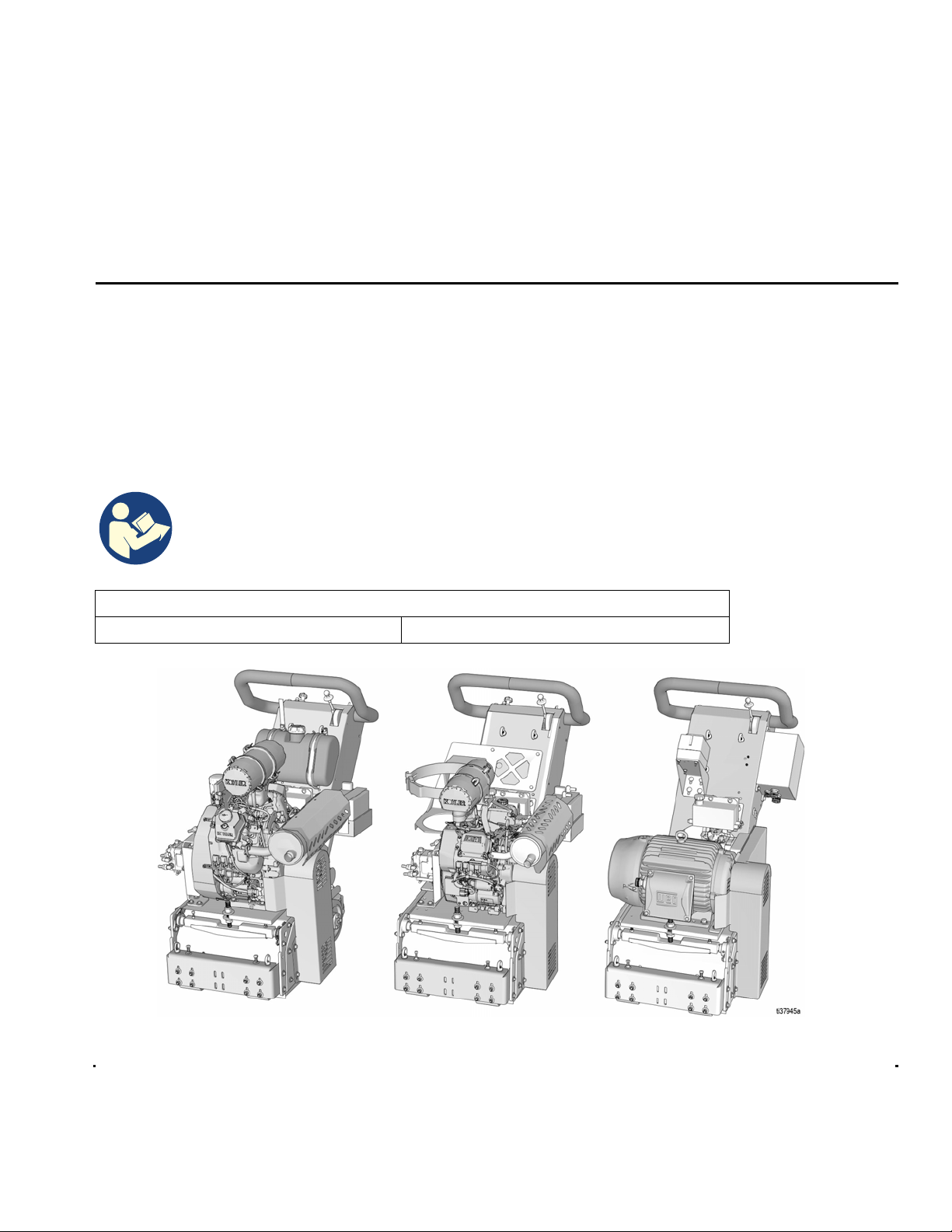
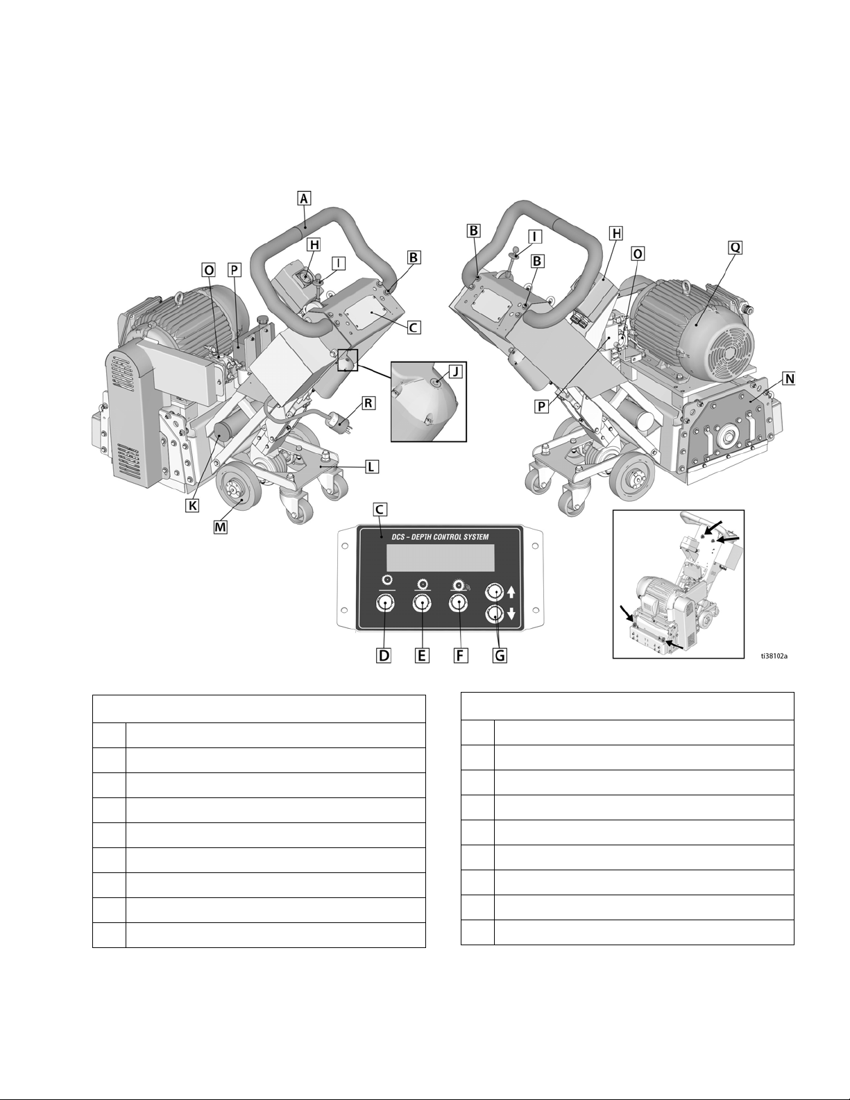
FS351 G DCS (Gas) . . . . . . . . . . . . . . . . . . . . . . . . . . . 7
FS351 P DCS (Propane) . . . . . . . . . . . . . . . . . . . . . . . 8
FS351 E DCS (Electric) . . . . . . . . . . . . . . . . . . . . . . . . 9
Setup . . . . . . . . . . . . . . . . . . . . . . . . . . . . . . . . . . . . . . . . . 10
Propane Tank . . . . . . . . . . . . . . . . . . . . . . . . . . . . . . . 10
Lifting Instructions . . . . . . . . . . . . . . . . . . . . . . . . . . . . 10
Handlebar Adjustment . . . . . . . . . . . . . . . . . . . . . . . . 11
Engine Kill Button (Gas/Propane) . . . . . . . . . . . . . . . .11
Drum Installation/Replacement . . . . . . . . . . . . . . . . . . 12
DCS Control . . . . . . . . . . . . . . . . . . . . . . . . . . . . . . . . 13
Operation . . . . . . . . . . . . . . . . . . . . . . . . . . . . . . . . . . . . . 17
Machine Start Up (Gas & Propane) . . . . . . . . . . . . . . 17
Machine Start Up (Electric) . . . . . . . . . . . . . . . . . . . . . 17
When operating... . . . . . . . . . . . . . . . . . . . . . . . . . . . . 18
Hydrostatic Drive Operation . . . . . . . . . . . . . . . . . . . . 18
DCS Instructions . . . . . . . . . . . . . . . . . . . . . . . . . . . . . 19
Repair . . . . . . . . . . . . . . . . . . . . . . . . . . . . . . . . . . . . . . . . 21
Drive Belt Replacement . . . . . . . . . . . . . . . . . . . . . . . 21
Hydraulic Belt Replacement (Electric Models only) . . 22
Bearing Housing Replacement . . . . . . . . . . . . . . . . . . 23
Drive Pulley Replacement . . . . . . . . . . . . . . . . . . . . . . 24
Maintenance Checklist . . . . . . . . . . . . . . . . . . . . . . . . . . 25
Gas/Propane Models only . . . . . . . . . . . . . . . . . . . . . . 25
All Models . . . . . . . . . . . . . . . . . . . . . . . . . . . . . . . . . . 25
Purge Procedures . . . . . . . . . . . . . . . . . . . . . . . . . . . . 26
Front Wheel Adjustment . . . . . . . . . . . . . . . . . . . . . . . 26
Recycling and Disposal . . . . . . . . . . . . . . . . . . . . . . . . . . 27
Rechargeable Battery Disposal . . . . . . . . . . . . . . . . .27
End of Product Life . . . . . . . . . . . . . . . . . . . . . . . . . . . 27
DCS Control Translations . . . . . . . . . . . . . . . . . . . . . . . . 28
Troubleshooting . . . . . . . . . . . . . . . . . . . . . . . . . . . . . . . . 30
DCS Error Codes . . . . . . . . . . . . . . . . . . . . . . . . . . . . 32
DCS Actuator Rod Does Not Move . . . . . . . . . . . . . . . 33
Parts - Main Housing Assembly (All Models) . . . . . . . . 34
Parts List - Main Housing Assembly (All Models) . . . . 35
Parts - Front Wheel / Wheel Carrier Assemblies (All Models)
36
Parts List - Front Wheel / Wheel Carrier Assemblies (All
Models) . . . . . . . . . . . . . . . . . . . . . . . . . . . . . . . . 37
Parts - Guidebar / Vacuum Assemblies (All Models) . . 38
Parts List - Guidebar / Vacuum Hose Assemblies (All
Models) . . . . . . . . . . . . . . . . . . . . . . . . . . . . . . . . 39
Parts - Hydraulic Motor / Rear Assembly (All Models) . 40
Parts List - Hydraulic Motor / Rear Assembly (All Models)
41
Parts - Support System / Hydraulic Tank (All Models) . 42
Parts List - Support System / Hydraulic Tank (All Models)
43
Parts - Motor / Hydraulic Assemblies (Gas) . . . . . . . . . 44
Parts List - Motor / Hydraulic Assemblies (Gas) . . . . . 45
Parts - Hydraulic Fittings / Fuel Tank Assemblies (Gas) 46
Parts List - Hydraulic Fittings / Fuel Tank Assemblies (Gas)
47
Parts - Pulley Assemblies (Gas) . . . . . . . . . . . . . . . . . . . 48
Parts List - Pulley Assemblies (Gas) . . . . . . . . . . . . . .49
Parts - Dashboard / Battery Assemblies (Gas) . . . . . . . 50
Parts List - Dashboard / Battery Assemblies (Gas) . . 51
Parts - Motor / Hydraulic Assemblies (Propane) . . . . . . 52
Parts List - Motor / Hydraulic Assemblies (Propane) . 53
Parts - Propane Tank / Dashboard Assemblies (Propane)
54
Parts List - Propane Tank / Dashboard Assemblies
(Propane) . . . . . . . . . . . . . . . . . . . . . . . . . . . . . . . 55
Parts - Pulley Assemblies (Propane) . . . . . . . . . . . . . . . 56
Parts List - Pulley Assemblies (Propane) . . . . . . . . . . 57
Parts - Battery Assembly (Propane) . . . . . . . . . . . . . . . . 58
Parts List - Battery Assembly (Propane) . . . . . . . . . . . 59
Parts - Electrical Components (Electric) . . . . . . . . . . . .60
Parts List - Electrical Components (Electric) . . . . . . . 61
Parts - Hydraulic Motor Assemblies (Electric) . . . . . . . 62
Parts List - Hydraulic Motor Assemblies (Electric) . . . 63
Parts - Hydraulic Assembly (Electric) . . . . . . . . . . . . . . 64
Parts List - Hydraulic Tank Assembly (Electric) . . . . . 65
Parts - Pulley Assemblies (Electric - 480V & 380V) . . . 66
Parts List - Pulley Assemblies (Electric 480V & 380V) 67
Wiring Diagram . . . . . . . . . . . . . . . . . . . . . . . . . . . . . . . . 68
Gas Models . . . . . . . . . . . . . . . . . . . . . . . . . . . . . . . . . 68
Propane Models . . . . . . . . . . . . . . . . . . . . . . . . . . . . . 69
Electric Models (480V) . . . . . . . . . . . . . . . . . . . . . . . . 70
Electric Models (380V) . . . . . . . . . . . . . . . . . . . . . . . . 71
Technical Data . . . . . . . . . . . . . . . . . . . . . . . . . . . . . . . . . 72
SMITH Standard Warranty . . . . . . . . . . . . . . . . . . . . . . . . 74
SMITH Information . . . . . . . . . . . . . . . . . . . . . . . . . . . . . . 74

Warnings
3A7832A 3
Warnings
The following warnings are for the setup, use, grounding, maintenance, and repair of this equipment. The exclamation
point symbol alerts you to a general warning and the hazard symbols refer to procedure-specific risks. When these
symbols appear in the body of this manual or on warning labels, refer back to these Warnings. Product-specific hazard
symbols and warnings not covered in this section may appear throughout the body of this manual where applicable.
WARNING
DUST AND DEBRIS HAZARD
Grinding concrete and other surfaces with this equipment can create dust that contains hazardous
substances. Grinding can also create flying debris.
To reduce the risk of serious injury:
• Control the dust to meet all applicable workplace regulations.
• Wear protective eye wear and a properly fit-tested and government approved respirator suitable for
the dust conditions.
• Use equipment only in a well-ventilated area.
• Grinding equipment must be used only by trained personnel who understand the applicable work-
place regulations.
ENTANGLEMENT AND MOVING PARTS HAZARD
Moving parts can pinch, cut or amputate fingers and other body parts.
• Keep clear of moving parts.
• Do not operate equipment with protective guards or covers removed.
• Do not wear loose clothing, jewelry or long hair while operating equipment.
• Before checking, moving, or servicing equipment, disable power. For gas/propane units, disconnect
negative (-) battery cable. For electric units, unplug power cord.
BURN HAZARD
Cutters and engine can become very hot during operation. To avoid severe burns, do not touch hot
equipment. Wait until equipment has cooled completely.
PERSONAL PROTECTIVE EQUIPMENT
You must wear appropriate protective equipment when operating, servicing, or when in the operating
area of the equipment to help protect you from serious injury, including eye injury, inhalation of dust or
chemicals, burns, and hearing loss. This equipment includes but is not limited to:
• Protective eye wear.
• Protective shoes.
• Gloves.
• Hearing protection.
• Properly fit-tested and government approved respirator suitable for the dust conditions.

Warnings
43A7832A
SKIN INJECTION HAZARD
High-pressure fluid from hose leaks, or ruptured components will pierce skin. This may look like just a
cut, but it is a serious injury that can result in amputation. Get immediate surgical treatment.
• Inspect hose before each use for cuts, bulges, kinks or any other damage.
• Replace damaged hose immediately.
• Replace hoses proactively at regular intervals based on your operating conditions.
• Tighten all fluid connections before operating the equipment.
• Keep clear of leaks.
• Do not stop or deflect leaks with your hand, body, glove, or rag.
• Never exceed hose Maximum Pressure or Temperature ratings.
• Only use chemicals that are compatible with hose materials. See Technical Specifications in this
manual. Read Safety Data Sheets (SDSs) and fluid and solvent manufacturer’s recommendations.
EQUIPMENT MISUSE HAZARD
Misuse can cause death or serious injury.
• Do not operate the unit when fatigued or under the influence of drugs or alcohol.
• Do not leave the work area while equipment is energized. Turn off all equipment when equipment is
not in use.
• Check equipment daily. Repair or replace worn or damaged parts immediately with genuine manu-
facturer’s replacement parts only.
• Do not alter or modify equipment.
• Use equipment only for its intended purpose. Call your distributor for information.
• Keep children and animals away from work area.
• Comply with all applicable safety regulations.
• Maintain a safe operating distance from other people in the work area.
• Avoid any pipes, columns, openings, or any other objects protruding from work surface.
WARNING

Warnings
3A7832A 5
Gasoline/Propane Engine Warnings
WARNING
FIRE AND EXPLOSION HAZARD -- GASOLINE
Flammable fumes, such as solvent and paint fumes, in work area can ignite or explode. To help pre-
vent fire and explosion:
• Use equipment only outdoors. Never use indoors or in enclosed spaces.
• Do not fill fuel tank while engine is running or hot; shut off engine and let it cool. Fuel is flammable
and can ignite or explode if spilled on hot surface.
• Eliminate all ignition sources, such as pilot lights, cigarettes, and portable electric lamps.
• Keep work area free of debris, including solvent, rags and gasoline.
• Keep a fire extinguisher in work area.
FIRE AND EXPLOSION HAZARD -- PROPANE (LP GAS)
Propane is highly flammable and explosive. To help prevent fire and explosion:
• Use equipment only outdoors. Never use indoors or in enclosed spaces.
• Eliminate all ignition sources, such as pilot lights, cigarettes, and portable electric lamps.
• If you smell propane, shut off the machine immediately and close the propane tank fuel valve. Do not
use machine until you identify and correct the problem.
• Always turn off propane tank fuel valve when equipment is not in use.
• Do not store propane tanks, or equipment with a propane tank, inside a building or enclosed area.
• Keep a fire extinguisher in work area.
CARBON MONOXIDE HAZARD
Exhaust contains poisonous carbon monoxide, which is colorless and odorless. Breathing carbon
monoxide can cause death.
• Operate engine only outdoors. Never use indoors or in enclosed spaces.
BATTERY HAZARD
Lead-acid batteries produce explosive gases and contain sulfuric acid that can cause severe burns. To
avoid sparks and injury when handling or working with a lead-acid battery:
• Read and follow the battery manufacturer’s warnings.
• Exercise caution when working with metallic tools or conductors to prevent short circuits and sparks.
• Keep all sparks, flames, and cigarettes away from batteries.
• Always wear protective eyewear and protective equipment for face, hands, and body.
• If you have direct contact with battery fluid, flush with water and consult a physician immediately.
• Installation and maintenance must be performed by knowledgeable personnel only.

Warnings
63A7832A
Electric Motor Warnings
DANGER
SEVERE ELECTRIC SHOCK HAZARD
This equipment is powered by more than 240 V. Contact with this voltage will cause death or serious
injury.
• Turn off and disconnect power cord before servicing equipment.
• Connect only to grounded electrical outlets.
• Use only 4-wire extension cords.
• Ensure ground prongs are intact on power and extension cords.
• Do not expose to rain. Store indoors.
• All electrical wiring must be done by a qualified electrician and comply with all local codes and
regulations.
GROUNDING
This product must be grounded. In the event of an electrical short circuit, grounding reduces the risk of
electric shock by providing an escape wire for the electric current. This product is equipped with a cord
having a grounding wire with an appropriate grounding plug. The plug must be plugged into an outlet
that is properly installed and grounded in accordance with all local codes and regulations.
• Improper installation of the grounding plug is able to result in a risk of electric shock.
• This product is for use on a nominal 480 V or 380 V circuit and has a grounding plug similar to the
plugs illustrated in the figure below..
• Only connect the product to an outlet having the same configuration as the plug.
• Do not modify the plug provided; if it does not fit the outlet, have the proper outlet installed by a
qualified electrician.
• Do not use an adapter with this product.
• When repair or replacement of the cord or plug is required, only connect the grounding wire to the
extended ground blade or pin.
• The wire with insulation having an outer surface that is green with or without yellow stripes is the
grounding wire.
• Check with a qualified electrician or serviceman when the grounding instructions are not completely
understood, or when in doubt as to whether the product is properly grounded.
• Extension Cords:
• Use only a 4-wire extension cord that has a grounding plug and a grounding receptacle that accepts
the plug on the product.
• Make sure your extension cord is not damaged. If an extension cord is necessary, use 10 AWG
(6.0 mm2) minimum to carry the current that the product draws.
• An undersized cord results in a drop in line voltage and loss of power and overheating.
480 V 380 V

Component Identification
3A7832A 7
Component Identification
FS351 G DCS (Gas)
See Lifting
Instructions,
page 10.
Component
A Adjustable Handlebar
B Handlebar Adjustable Bolts
C DCS Control
D Hour Meter / Tachometer
E Home Button
F Zero Button
G Cut Depth Button
H Up / Down Button
I DCS Power Switch
JKey Switch
K Throttle Control
L Forward / Reverse Control Lever
M Engine Kill Button
N Manual Height Adjustment
OBattery
P Vacuum Port
Q Lift Carriage with Swivel Casters
R Self-Propelled Drive Wheels
S Removable Side Plate
T Air Intake / Filtration System
U Hydraulic Drive Pump
V Hydraulic Reservoir
W Engine (Kohler)
X Gas Tank
Component

Component Identification
83A7832A
FS351 P DCS (Propane)
See Lifting
Instructions,
page 10.
Component
A Adjustable Handlebar
B Handlebar Adjustment Bolts
C DCS Control
D Hour Meter / Tachometer
E Home Button
F Zero Button
G Cut Depth Button
H Up / Down Button
I DCS Power Switch
J Key Switch
K Throttle Control
L Forward / Reverse Control Lever
M Engine Kill Button
N Manual Height Adjustment
O Battery
P Vacuum Port
Q Lift Carriage with Swivel Casters
R Self-Propelled Drive Wheels
S Removable Side Plate
T Air Intake / Filtration System
U Hydraulic Drive Pump
V Hydraulic Reservoir
W Engine (Kohler)
X Propane Tank Bracket
Component

Component Identification
3A7832A 9
FS351 E DCS (Electric)
See Lifting
Instructions,
page 10.
Component
A Adjustable Handlebar
B Handlebar Adjustment Bolts
C DCS Control
D Home Button
E Zero Button
F Cut Depth Button
G Up / Down Button
H Motor Start Switch
I Forward / Reverse Control Lever
J Manual Height Adjustment
K Vacuum Port
L Lift Carriage with Swivel Casters
M Self-Propelled Drive Wheels
N Removable Side Plate
O Hydraulic Drive Pump
P Hydraulic Reservoir
Q Electric Motor
R Power Plug
Component

Setup
10 3A7832A
Setup
Propane Tank
Propane (LP gas) supply tank not provided by SMITH.
Supply tank must be vertically mounted and vapor
withdrawal type. Supply tank must be designed,
fabricated, and marked in accordance with specifications
and regulations for LP-Gas cylinders at: The U.S.
Department of Transportation (DOT); the National
Standard of Canada, CAN/CSA-B339, Cylinders,
Spheres, and Tubes for Transportation of Dangerous
Goods; the Transportable Pressure Vessels Regulations
2001 (S1 2001/1426); or the Gas Cylinders (Pattern
Approval) Regulations 1987 (SI 1987/116)(Pattern
Approval Regulations) for EEC-type cylinders under
European Directive 84/525/EEC, 84/526/EEC, and
84/527/EEC.
Check gas supply hose connection to propane cylinder.
Make sure fitting is free of debris before connecting to
tank. Make sure gas connection is screwed completely
on and is free of leaks.
NOTE: The propane tank connection hose is equipped
with a POL gas fitting. If a different sized fitting is
needed, see your local LP gas equipment supplier.
Lifting Instructions
• Only lift the equipment using all available lift points.
The lift chains must be angled at least 45° from the
horizontal.
• Lift the system with a lift apparatus rated
appropriately for the weight of the system. See
Technical Data, page 72.
• Lift the system using the lift eyes shown on the
appropriate illustration.

Setup
3A7832A 11
Handlebar Adjustment
The handlebars are equipped with a high-density
vibration suppression material to reduce operator
fatigue. To adjust the handlebars to a new position for
different height operators, please follow these steps:
1. Using a 9/16” wrench or socket, loosen the bolts on
both sides of the handlebars until the handlebar
moves freely.
2. Stand behind the machine and lightly tap the
handlebar to the desired position.
3. Re-tighten the bolts to 260-300 in-lb (29-34 N•m) to
lock the handlebars into position.
NOTE: Never operate equipment with loose
handlebars. The bolts must be fastened tightly to
ensure the handle is locked into position.
Engine Kill Button (Gas/Propane)
In the event of a malfunction or an accident (such as the
machine operator falling or losing footing), the FS351 is
equipped with a corded Engine Kill Button. Attach the
end of the cord to the operator’s belt or wrist, and snap
the clip into place on the button by raising the top of the
Engine Kill Button and inserting the clip into the gap. If
the operator becomes distanced too far from the
machine, the cord will detach from the button and the
machine will stop running. The engine can also be
stopped by pressing down on the Engine Kill Button.

Setup
12 3A7832A
Drum Installation/Replacement
Normal use will require periodic drum inspection and
may necessitate drum replacement. Time of
replacement will vary according to usage and load
factors.
Tools needed:
• 9/16” socket or wrench
• Rubber mallet
• 1-1/8” wrench
1. Turn DCS Power Switch ON. Wait until the FS351
cools off if it has been running.
2. Press Home Button on DCS Control to raise the
cutter drum off the work surface.
3. Using 1-1/8” and 9/16” wrench, lower jam nuts and
support bolts on engine/motor plate so that tension
is released off belt.
4. Remove six hex head cap screws from the Side
Plate using the 9/16” socket or wrench.
5. Remove the Side Plate (this may require the rubber
mallet to break it loose).
6. Slide out the drum assembly. Use caution as the
assembly is heavy.
7. Before replacing the drum onto hex shaft:
a. Check that all bearings are in good working
order.
b. Remove dirt and material build-up from inside
main housing and drum.
c. Apply grease to all metal contacts.
d. Check drum spacers for wear, replace if
necessary (if applicable).
8. Align and slide drum back onto the hex shaft.
9. Replace Side Plate (slide onto) hex shaft and
reinstall the six cap screws and torque to 40 ft/lbs
(54.2 N•m). Check that drum moves side to side and
drum spacers are free to move (if applicable).
10. To tension the belt, turn the base plate pivot nut with
the 1-1/8” wrench. This will raise the engine/motor
base plate. Use the 9/16” wrench to raise bolts into
place, locking jam nut when complete.
NOTE: An extra drum loaded with cutters for rapid
job site replacement is recommended.
Gas/Propane: To avoid injury from unexpected start
up, turn ignition OFF, remove key, and disconnect
spark plug wires before you service your unit.
Electric: To avoid injury from unexpected start up,
disconnect power plug before servicing your machine.
Once at home position, disconnect negative (-) battery
cable for gas/propane units. For electric units,
disconnect power plug. If more adjustment is needed at
this point, use the
Manual Height Adjustment
, page
20.

Setup
3A7832A 13
DCS Control
Buttons on the DCS Control have two functions, quick
press and long press. Quick press refers to pressing the
button and releasing the button quickly, while long press
is pressing the button and holding the button for two or
more seconds.
NOTE: “+” (plus) refers to above work surface. “-”
(minus) refers to below work surface.
Run Screen
Home Button
Quick Press: Takes the drum to its highest position.
Long Press: Brings up Menu Screen.
Zero Button
Quick Press: Takes the drum to the work surface.
Long Press: Reprograms the zero point to the current
drum position.
HOME
BUTTON
UP BUTTON
DOWN BUTTON
Current Drum
Position
Saved Cut Depth
ZERO
BUTTON
CUT DEPTH
BUTTON
DEPTH ..............+0.21"
TARGET........... --0.08"
ti35660a
FS351 DCS CONTROL

Setup
14 3A7832A
Cut Depth Button
Quick Press:
Takes the drum to the Cut Depth Target.
Long Press:
- If at or above zero point: Opens new screen to
select desired cut depth using up/down buttons.
• To exit without saving, quick press the Cut
Depth Button.
• To exit with saving, long press the Cut Depth
Button.
- If below zero point: Reprograms the Cut Depth
Target to the current drum position.
Up Arrow Button*
Quick Press: Raises the drum by 0.01” (0.25mm, 10
mil).
Long Press: Raises the drum to Home position.
Down Arrow Button*
Quick Press: Lowers the drum by 0.01” (25mm, 10
mil).
Long Press: Lowers the drum to Cut Depth Target.
* Handlebar Rocker Switch has the same functions as
Up and Down Arrow Buttons.

Setup
3A7832A 15
Menu Screens
To display the Menu Screens, hold down Home Button
from the Run Screen. To save menu settings and return
to Run Screen, hold down Home Button from any Menu
Screen.
To cycle through selections in each Menu Screen, use Up
and Down Arrow Buttons.
To advance to next Menu Screen, quick press the Home
Button.
Menu Screen #1 - Language
Select your desired language (English, Spanish, French,
German, or International Symbols).
Menu Screen #2 - Units
Select your desired depth units (inches, millimeters, or
mils).
Menu Screen #3 - Model Select
Your FS351 model name can be found on the handlebar
dashboard label. Select the model on the DCS Control
which matches the model you have. This ensures accu-
rate depth readings. Hold down Up or Down Arrow But-
tons to cycle through models.
Menu Screen #4 - Software revision
Displays the revision of the software on the DCS Control.

Setup
16 3A7832A
Menu Screen #5 - Error Codes
Displays the most recent error code and the total num-
ber of times that error has occurred. Cycle through pre-
vious error codes using Up/Down Buttons.
Error Codes
E04: High Voltage
E05: High Motor Current
E08: Low Voltage
E09: Hall Sensor Error
E12: High Current (short circuit)
E31: Home Button Error
E32: Zero Button Error
E33: Cut Depth Button Error
E34: Up Button Error
E35: Down Button Error
To clear an error code that appears while on the Run
Screen:
1. Turn DCS Power Switch OFF.
2. Address/Fix the issue.
3. Turn DCS Power Switch ON.
NOTE: See Repair Manual for more information on
Error Codes and Troubleshooting.

Operation
3A7832A 17
Operation
Machine Start Up (Gas &
Propane)
1. Turn DCS Power Switch ON.
2. Verify the Forward/Reverse Control Lever is in the
neutral (N) position.
3. Place the throttle lever at the “fast idle” position.
4. Start the engine.
5. Move throttle control to open or run position when
engine is warmed up.
6. Increase throttle to optimal machine operating
position.
NOTE: Engine speed for all drum assemblies is
3450 RPM.
7. Before removal, run the drum with the cutters not
touching the work surface. If there is excessive
vibration, re-balance the cutter setup, check bearing
condition, and/or make sure the drive shaft is
secured.
If the Engine Does Not Start
•
Turn the ON/OFF Switch on the Control Panel to ON.
• Check engine for proper gas and oil levels.
• Check the spark plug. Make sure socket areas are
clean and clear of debris, and the proper gap is set.
Replace if needed.
• Check the corded Engine Kill Button’s connections.
Make sure the corded safety stop “C” connector is
properly inserted into the Engine Kill Button.
Machine Start Up (Electric)
1. Turn motor ON/OFF switch to OFF.
2. Verify the Forward/Reverse Control Lever is in the
neutral (N) position.
3. Plug the machine in to the electrical source.
4. Turn motor ON/OFF switch to ON.
5. Before operating, run the drum with the cutters not
touching the work surface. If there is excessive
vibration, re-balance the cutter setup, check bearing
condition, and/or make sure the drive shaft is
secured.
If the Motor Does Not Start
• Make sure the motor is plugged into the electrical
source.
• Turn motor ON/OFF switch to ON.
Do not start machine while cutter head is in contact
with the work surface. Doing so can cause the
operator to lose control of the machine, resulting in
property damage and/or personal injury.
Electric: To avoid injury from unexpected movement,
ensure Power Switch is in the OFF position before
connecting or disconnecting the power cord. In the
event of a power failure or interruption, ensure Power
Switch is on the OFF position before restoring power. NOTICE
Make sure motor is rotating in the correct direction.
Look for clockwise rotation on the right side of the
machine at drum end shaft by turning on and off
quickly. Incorrect rotation will damage hydraulic pump
and could damage cutters if contact is made with the
work surface. If rotation is incorrect, exchange posi-
tions of two power wires at the plug. Do not loosen or
move the ground wire at the plug.

Operation
18 3A7832A
When operating...
Adjust the height of the cutter drum. Set the depth of cut
to allow the cutters to go through only the materials to be
removed. Make certain that the drum is positioned to
where only the cutters strike the work surface, and that
the drum assembly never comes in to contact with the
work surface. The cutter tips alone should strike the
work surface (1/8” to 1/4” maximum depth per removal
pass on new cutters). The drum will not survive work
surface contact.
Remove materials in several passes rather than one
deep pass. Several tests will show the best, most
appropriate cutter depth. Use a forward/backward
pattern to achieve your desired finish.
When the job is complete, or the operator wants to cease
work, raise the drum above the work surface by pressing
home button on DCS control.
•For gas units, stop the machine with the key switch
or power switch.
•For propane units, stop machine with the key
switch or power switch, then close the propane
supply valve.
•For electric units, stop machine by turning motor
power switch OFF, and unplug the machine from the
electrical source.
The drum assembly must be removed daily and
inspected for drum wear, hole elongation and possible
weld separation. Replace the cutter shafts every 40
hours, or prior to any drum wear. If the drum’s center
holes are elongated, order another SMITH cutter drum.
Hydrostatic Drive Operation
Engine/motor must be warmed up and at desired speed.
Verify the Forward/Reverse Control Lever is in the
neutral (N) position. Lower the unit to raise the carriage
wheels off the work surface and set the unit onto the
drive wheels. The Forward/Reverse Control Lever
should be in the neutral (N) position and the wheels
should not be turning. At this point the unit can be
propelled forward or reverse by pressing down on the
Control Lever and moving the Control Lever either
forward or backward.
The “live” axle will help move the unit in a straight line.
However, keep both hands on the handle for safe
operation and minor directional corrections.
SEVERE ELECTRIC SHOCK HAZARD
Electric: Keep the extension cord clear of machine
travel path
NOTICE
Cutting too deep will cause premature wear to cut-
ters, shafts, drum and other components.

Operation
3A7832A 19
DCS Instructions
Each time the DCS Control is turned on, the DCS actua-
tor will travel to the Home position.
Once the DCS Control finds Home, ensure the correct
model is selected as well as your desired language and
units. See Menu Screens, page 15, for instructions on
changing these settings.
Set Zero Point:
With the engine/motor on, lower the drum by pressing
the Down Arrow Button until you hear the cutters make
contact with the work surface. Hold down the Zero Button
for 2 seconds. Your Zero Point has now been saved.
NOTE: The Cut Depth Target is based off of the Zero
Point. Re-program the Zero Point if the drum is changed
or worn.
Set Cut Depth Target:
Quick press the Zero Button to take the drum to the work
surface. Set the Cut Depth Target by:
1. Quick pressing the Down Arrow Button as many
times as needed to achieve your target. Then long
press the Cut Depth Button to save your target.
NOTE: This method will lower the cutting drum into
the work surface as you set your cut depth.
OR
2. From the Zero Point, long press the Cut Depth But-
ton until a new screen pops up. Use the Down Arrow
Button to enter your Cut Depth Target. Then long
press the Cut Depth Button to save your target and
return to the Run Screen.
NOTE: This method will keep the cutting drum sta-
tionary as you set your Cut Depth Target.

Operation
20 3A7832A
The DCS Control is now ready to grind/scarify.
NOTE: The Zero Point and Cut Depth are referenced
from the Home position. Recalibrate your DCS Control
periodically by pressing the Home button.
NOTE: Pressing any button while the drum is moving to
Zero or Cut Depth will stop the command and halt the
drum from moving any further up or down until another
button is pressed.
Manual Height Adjustment
If the DCS Control is not usable (dead battery, etc.), the
drum height can be adjusted using the Manual Height
Adjustment feature.
1. Remove fuse from fuse holder near positive battery
terminal. This will protect the battery from damage.
2. Use a 6mm hex key to remove the screw plug on
the top of the linear actuator.
3. Insert 6mm hex key into the port the screw plug was
removed from.
• One revolution of the hex key results in 1/16” (1.6
mm, 62.5 mil) of adjustment at the cutter drum.
• Rotate counterclockwise to raise the drum; rotate
clockwise to lower the drum.
4. Once the desired depth is achieved, replace the
screw plug in order to keep water and dust out.
NOTICE
Max rotation speed is one revolution per second. Do
not use power tools in the Manual Height Adjustment
port. Doing so will cause damage to the actuator.
Other manuals for FS351 Series
1
This manual suits for next models
7
Table of contents
Other Smith Lawn And Garden Equipment manuals