Smoke Guard 4000 User manual

Model 4000
| Installation Manual
Perimeter Fire Curtains
287 N. Maple Grove. Boise, ID
83704
P. (800) 574-0330 F. (208)
639-7851
if@ k d

2
Table of Contents
Section 1: System Overview ................................................................................................................................. 4
1.1 – Major Components................................................................................................................................. 4
1.2 – Changing System Settings...................................................................................................................... 6
1.3 – System Orientation................................................................................................................................. 7
1.4 – Site Verification...................................................................................................................................... 7
1.5 – Checklist................................................................................................................................................. 8
Section 2: Main Controller Installation and Conduit Routing............................................................................ 9
2.1 – Installing the Main Controller .............................................................................................................. 10
Section 3: Housing............................................................................................................................................... 11
Assembling the Housing Sections..................................................................................................................... 11
3.1 – Drive Motors......................................................................................................................................... 11
3.2 – Optional Satellite Controllers & Junction Boxes ................................................................................. 13
Installing the Housing Sections......................................................................................................................... 14
3.3 – Installing Housing Top Sections........................................................................................................... 14
3.4 – Motor and Controller Cabling .............................................................................................................. 16
Section 4: Drive System...................................................................................................................................... 17
Assemble the Drive System .............................................................................................................................. 17
4.1 – Bevel Gear Assemblies......................................................................................................................... 17
4.2 – U-Joints................................................................................................................................................. 18
4.3 – Drive Shafts.......................................................................................................................................... 19
4.4 – Additional Drive Shafts........................................................................................................................ 19
4.5 – Up Limit Switch ................................................................................................................................... 20
Section 5: Electrical Connections....................................................................................................................... 22
5.1 – 120VAC Connections........................................................................................................................... 22
5.2 – Main Controller Cables ........................................................................................................................ 23
5.3 – Initiating Device Circuit....................................................................................................................... 24
5.4 – Optional Keyed Test Deploy Switch.................................................................................................... 24
5.5 – Optional Door Activation Switches...................................................................................................... 25
5.6 – Satellite Controller Chain Cables......................................................................................................... 25
5.7 – Main Controller Settings ...................................................................................................................... 26
5.8 – Wiring Diagram.................................................................................................................................... 27
Section 6: Curtain System .................................................................................................................................. 28
Test the Drive System....................................................................................................................................... 28

3
6.1 – Test the Motors..................................................................................................................................... 28
6.2 – Drive Chain........................................................................................................................................... 28
6.3 – Testing the Drive Line.......................................................................................................................... 29
Assemble the Curtain System ........................................................................................................................... 30
6.4 – Attach the Metal Tape .......................................................................................................................... 30
6.5 – Curtain Tray.......................................................................................................................................... 32
6.6 – Setting Tape Tension & Levelling The Curtain Tray........................................................................... 34
6.7 – Adjusting the Up Limit Switch............................................................................................................. 36
6.8 – Layout the Curtain................................................................................................................................ 38
6.9 – Assemble the Curtain............................................................................................................................ 38
6.10 – Optional Guide Pins ........................................................................................................................... 40
6.11 – Attaching Curtain to Housing............................................................................................................. 40
6.12 – Attaching Curtain to Curtain Tray...................................................................................................... 42
Installing Curtain System Components............................................................................................................. 43
6.13 – Installing Optional Side Guides.......................................................................................................... 43
6.14 – Attaching Covers................................................................................................................................ 44
6.15 – Install the batteries.............................................................................................................................. 44
6.16 – Retaining Clips................................................................................................................................... 45
Section 7: System Testing .................................................................................................................................. 46
7.1 – Calibration Sequence............................................................................................................................ 46
7.2 – Test Optional Keyed Switch................................................................................................................. 47
7.3 – Test Optional Door Activation Switches.............................................................................................. 47
7.4 – Sewing Curtain Sections....................................................................................................................... 48
Section 8: Troubleshooting................................................................................................................................. 49
Appendix............................................................................................................................................................... 51
A1 – Contact Smoke Guard .............................................................................................................................. 51
A2 – M4000 Installation Checklist ................................................................................................................... 52
Section 2: Control System................................................................................................................................. 52
Section 3: Housing............................................................................................................................................ 52
Section 4: Drive System.................................................................................................................................... 53
Section 6: Curtain.............................................................................................................................................. 54
Section 7: System Testing................................................................................................................................. 55
A3 – Glossary.................................................................................................................................................... 56

4
Section 1: System Overview
The Model 4000 Perimeter Fire Curtain (M4000) is a motorized smoke and fire protection system housed in the
ceiling of a building. The system uses one or more motors to lower a specialized curtain around a strategic
location. When not in use the M4000 is retracted into a housing unit which maintains the aesthetic of the facility
it is installed in.
NOTE: Each M4000 is specific to its installation site. This guide provides general installation steps for
components. Your installation may require some or all of these steps.
1.1 – Major Components
Figure 1 - The Model 4000 Perimeter Fire Curtain with optional Side Guides.
A – M4000 Housing: The Housing contains all of the motors, drive shafts, pulley systems and the
Curtain for the M4000.
B – Optional Side Guides: Some units may include the optional Side Guides, which guide the
Curtain on rails.
C – Curtain: The curtain is made from specialized fabric and designed to withstand fire and smoke.
D – Curtain Tray: The Curtain Tray lowers and raises the Curtain. When not in use the Curtain
Tray has aesthetically pleasing exterior paneling.
E – Metal Tape: The Metal Tape is used to lower the Curtain from the Housing.
D
A
B C E

5
Main Controller
The Main Controller serves as housing for batteries, control switches, status LEDs and system control switches
which can be used to put the unit into different operating modes. In the event the unit has additional Satellite
Controllers and other hardware, the Main Controller serves as the hub for the entire system.
A – Low Voltage Power Block: The low voltage power block is the terminal location for most of
the systems on the M4000 including optional features.
B – High Voltage Power Block: The high voltage power block is the main input point for the
M4000 power system.
C – PCA: The Printed Circuit Assembly (PCA) controls the normal operation of the M4000. The
PCA is also the location of the configuration switches which are used to change the
system from Armed to Jog Mode. The control switches used to jog the system are
also located by the PCA.
D – Status LEDs and Test Switch: The status LEDs indicate normal operation and errors on the
M4000. These lights can be used for troubleshooting the system and verifying certain
conditions. The system test microswitch is also found on the LED board.
E – Batteries: The batteries provide emergency power to the M4000, enabling it to deploy in the
event of primary power loss.
Figure 2 – (Left) The M4000 Main Controller seen with outer cover. (Right) The interior of the Main Controller.
A B
C
D
E

6
1.2 – Changing System Settings
Over the course of the installation it will be necessary to change the operating mode of the M4000. The unit can
operate in two modes:
Jog Mode: Enables the use of the control buttons to jog the system up and down at will.
Armed: The normal setting for the curtain after it has been installed. This is also the mode used for
testing.
The operating modes can be altered by changing settings on the DIP switch on the system PCA.
Additional DIP switch settings as well as settings for Satellite Controllers can be found in Section 5.
Step 1 – Power off the Main Controller and disconnect the battery.
Step 2 – To change system settings, move the #6 DIP switch.
oUP for Armed.
oDOWN for Jog Mode.
Step 3 – Wait 3 seconds to allow the system to restart. Then power on the Main Controller and re-connect the
battery.
WARNING: Be sure the Main Controller is powered down before changing DIP switch settings.
Figure 3 – The #6 DIP switch is used to change between operating modes on the M4000.

7
1.3 – System Orientation
The M4000 is installed to a Header at the installation site. Although the unit will be oriented with its top plate
anchored to the Header.
Illustrations in this guide will present the M4000 in the position it will be in for its final installation.
1.4 – Site Verification
Prior to installing the M4000 it is critical that certain requirements are met at the work site. This will ensure safe
and successful installation of the M4000.
Electrical:
Point to point wiring from the location of the M4000 to its Main Controller must be in place before the
system can be installed. Work with your electrical contractor to verify that the required circuit is in place
for installation. Consult the Installation Layout Sheets (ILS) located in the shipping manifest as well as
Section 2 and Section 5. for more information on wiring.
Work Site:
Measure mounting surfaces and correct framing and finishing variances prior to installing the M4000.
Consult your architectural diagrams and make any alterations before installing the unit. Because each
M4000 unit is unique to its installation site, only your Installation Layout Sheets and architectural
documents will apply to your installation.
Materials:
Check that all components for the M4000 are ready for installation. Use your bill of materials shipped
with the product to verify your parts list. Because each M4000 unit is unique to its installation site, only
your Installation Layout Sheets and bill of materials will apply to your installation.
Top
Bottom
Front /
Office side
Back /
Atrium side
Figure 4 – The M4000 seen from the side. The front of the system houses the motors and other
components.

8
Staging:
Using the Installation Layout Sheets included with your unit, stage components on the floor around the
worksite to ensure each section of your unit has all the parts necessary for installation. Each section is
numbered and depending on what length and how many corners, each section may require additional
motors and Satellite Controllers.
Stage components in a manner that is appropriate for your worksite.
NOTE: The motors and controls are generally meant to service a 9’ section. Long sides may require more than
one motor and additional hardware. There should be approximately one motor for every 20’ of section.
1.5 – Checklist
To help keep track of the installation process and ensure that the M4000 is correctly installed, utilize the check
boxes that verify certain critical steps have been completed. A full checklist sheet is available in the appendix.
This is an example of how checklist items will appear throughout the installation.

9
Section 2: Main Controller Installation and Conduit Routing
It is strongly recommended to maintain easy access and a line of sight from the control system to the
M4000 Curtain. Remote installations make communication difficult during installation and servicing.
An optimal location to place the Main Controller is above removable ceiling tiles adjacent to the
Curtain.
WARNING: The Main Controller must be within 30 conduit feet of the unit.
NOTE: This product is intended to be installed in accordance with the National Electric Code NFPA
80, National Alarm Code NFPA 80 and within the limits of the authority having jurisdiction.
Consult with site GC/electrician to identify Main Controller location. Reference your
Installation Layout Sheets to determine conduit routing paths. Requirements:
Main Controller must be within 30 conduit feet of the Main Junction Box mounting location.
1” conduit is routed between the Main Controller low voltage compartment and Main Junction
Box.
½” conduit is routed to Main Controller high voltage compartment to supply 120VAC.
A 120VAC service disconnect is required at the Main Controller.
NOTE: Only low voltage DC is run between the Main Controller and Main Junction Box.
Consult with site GC/electrician to coordinate additional power drops around perimeter of
curtain housing (not required for single motor system). Reference your Installation Layout
Sheets to determine conduit routing paths and number of circuits. Requirements:
½” conduit is required at each High Voltage Junction Box location on the curtain housing
to supply 120VAC.
A 120VAC service disconnect is required at each High Voltage Junction Box location.
Consult with site GC/electrician to coordinate routing of conduit between Main Controller low
voltage compartment and initiating device (smoke detector or fire alarm). Requirements:
½” conduit is required between initiating device and Main Controller low voltage
compartment.
Two 18 or 20 AWG stranded wires labeled 14 and 15 between initiating device and Main
Controller low voltage compartment.
NOTE: Wires 14 and 15 are connected to the Normally Open contacts of the initiating device in
parallel with the Smoke Guard EOL-Diode.
Consult with site GC/electrician to identify optional Wall Switch and/or Door Activation
Switches. Reference your Installation Layout Sheets to determine conduit routing paths and
number of circuits. Requirements:
½” conduit is required between Wall Switch box and Main Controller low voltage
compartment.
Two 18 or 20 AWG stranded wires labeled 16 and 17 between Wall Switch box and
Main Controller low voltage compartment.

10
½” conduit is required between Door Activation Switch box(es) and Main Controller low
voltage compartment.
Two 18 or 20 AWG stranded wires for each switch between Wall Switch box and Main
Controller low voltage compartment. First switch labeled 11 and 13, second switch
labeled 12 and 13.
2.1 – Installing the Main Controller
Step 1 – Using the Installation Layout Sheets
included with your unit, mark the target
conduit locations on the wall. (junction
boxes, service disconnect, Main Controller,
Housing locations.)
NOTE: Some installations may require additional
components.
Step 2 – Mount the Main Controller in an easily
accessible location within 30 conduit feet of
the primary motor.
Step 3 – Mount the service disconnect next to the
Main Controller.
Step 4 – Supply the Installation Layout Sheets to the
electrical contractor for conduit installation.
Install the Main Controller.
The control system is now installed. Verify correct installation by checking all
installation checklist items.
STOP
Figure 5 – The mounting points seen on the side of the Main
Controller.
16”

11
Section 3: Housing
The Housing of the M4000 contains the motors, drive shafts and other components which enable the Model
4000 to operate. These components are mounted to the housing structure and the housing is then attached to the
worksite. Installation requirements may vary depending on your worksite.
NOTE: The Housing should be assembled prior to mounting the unit to the header.
Layout all Housing sections under the installation site according to the Installation Layout Sheets
shipped with the unit. Mark Housing outer alignment lines on mounting surface.
Assembling the Housing Sections
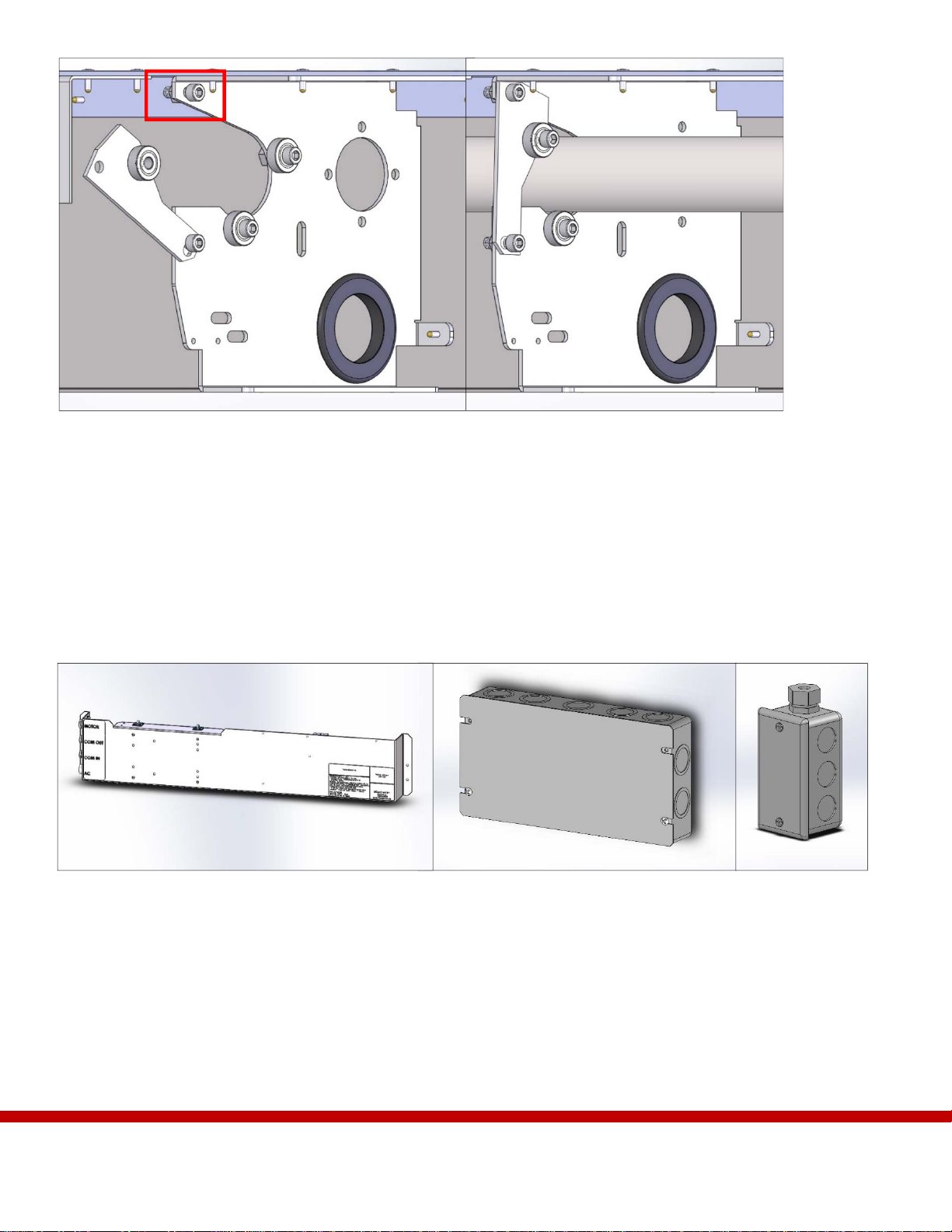
3.1 – Drive Motors
The curtains of the M4000 are raised and lowered using a system of drive shafts and motors. These steps will
show you how to install a motor in your system.
Step 1 – Locate the motor mounting hole on the support bracket.
Step 2 – Insert the motor into the 2” holes on the support brackets as seen in Figure 6. Ensure that the motor is
mounted so that the motor drive shaft is on the same side as the pulley on the top of the housing.
Figure 6 – A housing section highlighting the motor mounting points viewed if the unit was installed in the
ceiling. During assembly you may have the hardware oriented differently than in this illustration. Be sure to
verify what orientation you are working from to avoid assembly errors.
M5-12mm holes
Motor mounting
holes

12
Step 3 – Use hand tools to secure the motor by fastening the four, M5-12mm bolts located around the motor
mounting hole as seen in Figure 6.
WARNING: Motor components are fragile. Using an impact hammer, or other power tool, may damage to
components.
Step 3 – Attach drive sprocket to the motor drive shaft. Position the sprocket so it is evenly spaced on the motor
drive shaft, and tighten with set screw.
Attach motors with supplied hardware according to Installation Layout Sheets.
Attach drive sprocket. Ensure sprocket is evenly spaced on the motor drive shaft and tighten set
screws.
Step 4 – Loosen all rotating plates on the support brackets and rotate them down so the drive shaft can be
placed in the Housing later in the installation. See Figure 8 for the location of the rotating plate bolt.
Figure 7 – An example of a correctly installed motor and drive sprocket. Note that the drive sprocket will always need to be able
to line up with the drive shafts later in the installation.
13
3.2 – Optional Satellite Controllers & Junction Boxes
Some installations will require additional motors, junction boxes and Satellite Controllers to operate properly.
Reference your Installation Layout Sheets to determine if these steps apply to your installation. These steps will
show you how to install additional components to your M4000 system. If these steps do not apply to your
installation, proceed to Section 3.3.
For more information on Satellite Control wiring see Section 5.
NOTE: Every system will include one Main Junction Box.
Step 1 – Attach Satellite Controllers to the Housing using the included hardware. See Figure 10 for attachment
locations
Step 2 – Attach additional junction boxes using the included hardware. See Figure 10 for attachment locations.
Rotating plate
Figure 9 – (Left) A Satellite Controller. (Center) A Main Junction Box. (Right) A High Voltage Junction Box.
Figure 8 – (Left) The rotating plate on the support bracket can be moved by loosening the indicated bolt. (Right) The drive
shaft fits into the support bracket behind the rotating plate.
14
(If applicable) Install Satellite Controllers and junction boxes.
Installing the Housing Sections
3.3 – Installing Housing Top Sections
WARNING: Large 9’ sections may require 3 or more people for installation. Additional people may be needed
to hold the Housing while it is temporarily anchored.
WARNING: Do not lift the Housing sections by the motor.
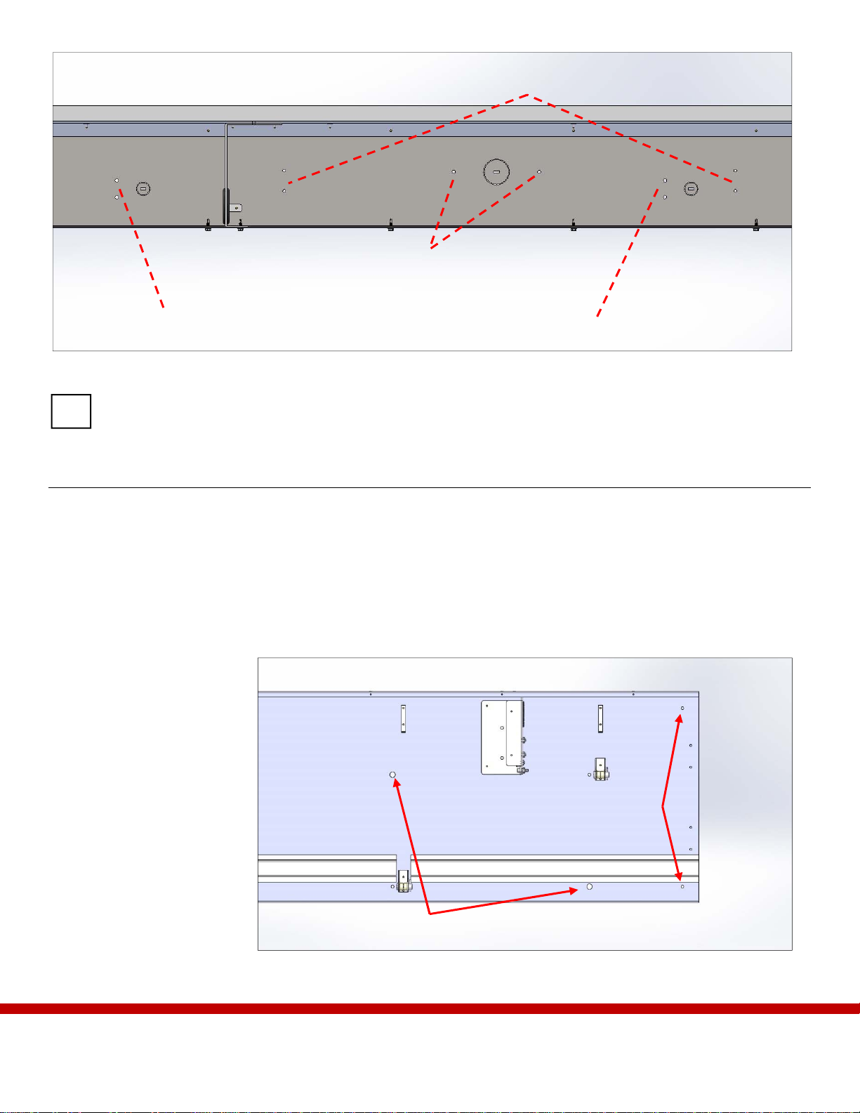
Each section of Housing has
oversized ½” pre-drilled
holes for initial anchors
which will hold the Housing
until the permanent anchors
can be installed. At this
point, adjustments to the
alignment of the housing
sections can be made if
necessary. The Housing can
then be permanently
attached by inserting
anchors through the smaller
¼” pre-drilled holes on the
Housing sections see Figure
11 for location details.
Figure 11 – Initial and permanent anchor points on the top plate of the Housing as seen from
the bottom.
Initial anchor points
Permanent
anchor points
Figure 10 – Mounting locations for additional hardware as seen from the front of the unit.
High Voltage Junction Box
Secondary High Voltage Junction Box
Main Junction Box
Satellite Controller

15
Step 1 – Layout all the Housing sections under the installation site according to the Installation Layout Sheets
shipped with your unit.
Step 2 – Use chalk or other erasable writing tool to mark where the outside of the Housing will align on the
header.
Step 3 – For systems installed into a pocket, install the back cover and front cover plates prior to anchoring the
header.
NOTE: It may be necessary to pre-install the outer covers of the top plates in instances where the front side of
the unit is exposed due to the ceiling soffit. For information on the outer covers see Section 6.14.
Step 4 – Position a section against the header so that the front side faces away from the area the Curtain is
meant to contain.
NOTE: For systems in an L or U shape, start installation at one end and work toward the other.
Step 5 – Apply the #8 or #10 initial anchors through the ½” pre-drilled holes using the supplied oversized
washers.
Step 6 – Apply initial anchors to all other sections.
Install all initial anchors through pre-drilled ½” holes.
Step 7 – Make any necessary adjustments to ensure the Housing sections line up properly.
Align all Housing sections.
Step 8 – Once sections are properly aligned, install the permanent #12 anchors through the ¼” pre-drilled holes.
WARNING: The requirements for your anchors may differ from this guide. Consult your architectural
drawings to verify the requirements for your anchors.
Install all permanent #12 anchors through pre-drilled ¼” holes.

16
3.4 – Motor and Controller Cabling
Step 1 – Feed motor and controller cables through the large
grommet holes on the Housing assembly as seen in
Figure 12.
Step 2 – Plug wiring harnesses into controllers so that all
hardware is connected.
Step 3 – Secure motor and controller cabling with zip ties
and clip wires into cable mounts so that there is 2”
of clearance from the cables to the bottom edge of
the Housing.
NOTE: Maintaining 2” of clearance between cables and the
bottom of the M4000 will help avoid accidental
damage when the cover pieces are installed later.
Step 4 – Ensure all electronics are connected.
Route cables and feed through the large grommet holes on the support brackets. Secure with zip ties
and ensure there is 2” of clearance above the bottom edge of the Housing.
Ensure all systems are linked by cabling, and that harnesses are plugged in.
Figure 12 – The grommets are located on the
support brackets of the Housing assemblies.
Grommet hole

17
Section 4: Drive System
The drive system is made up of separate sections. The number of sections varies depending on the length of the
system. Each section contains drive shafts which serve as spools for the Metal Tape which raises and lowers the
Curtain. Sections meeting at corners are coupled with a U-joint assembly or bevel gear assembly depending on
the angle of the corner. The drive system also includes components which aid in system calibration such as the
Up Limit Switch.
NOTE: Following assembly of all components, the drive system will be tested to ensure proper operation.
Following a successful test of the drive line, all fasteners will be tightened on all assembled
components. For more information on the drive line testing see Section 6.1.
Assemble the Drive System
4.1 – Bevel Gear Assemblies
Bevel gear assemblies are used to connect M4000 sections that meet at a 90° angle. For all other angles a U-
Joint is used. Reference your Installation Layout Sheets to determine if these steps apply to your installation.
These steps will show you how to install additional components to your M4000 system. If these steps do not
apply to your installation, proceed to Section 4.3.
Step 1 – Layout bevel gear assemblies in the corner sections of the Housing top plates. Refer to your
Installation Layout Sheets to verify the correct location.
Step 2 – Square the bevel gear to the Housing.
Square the bevel gear.
Step 3 – Secure bevel gear to Housing through pre-
drilled mounting holes on the top plate.
Secure the bevel gear to the Housing.
NOTE: Not all corner sections have rotating plates to
secure drive shafts. Refer to your layout
sheets to verify the components of your
installation.
Step 4 – Install and tighten both ¼-20 bolts at the bevel gear shaft. See Figure 13 for an illustration of a bevel
gear shaft.
Step 5 – Complete installation of drive shafts at the bevel gear assemblies until all drive shafts are fastened.
Bevel gear shaft
Figure 13 – A bevel gear assembly showing the four mounting
points on top of the assembly and gear shafts.

18
4.2 – U-Joints
If your M4000 uses U-Joints, this step will serve as the first step in Drive Shaft installation as this step requires
the U-Joint be connected to drive shafts. Connect drive shafts to the U-joint prior to installation. You can learn
more about installing drive shafts in Section 4.3.
Step 1 – Layout U-joint sections around the installation where appropriate. Refer to your Installation Layout
Sheets to verify the correct location. U-joints may be accompanied by short sections of drive shaft.
Step 2 – Connect drive shaft sections to either side of the U-joint at the U-joint coupler.
Figure 14 – The U-Joint is pictured from above with a section of drive shaft. Note the thrust bearing assembly clamped down around the bracket.
Attach U-joints to drive shafts.
Install U-joint section with drive shafts into Housing and tighten collar clamps.
Step 3 – Secure drive shaft sections into the Housing by closing the rotating plate over the shafts.
Step 4 – Tighten the collar clamps around the thrust bearings on the U-joint support bracket.
NOTE: The U-joint attaches to non-coupler ends of the drive shaft. Depending on your installation it may not
be necessary to install short drive shafts. Refer to your layout sheets to verify the requirements for your
installation.
U-joint Thrust bearing assembly
U-joint coupler
19
4.3 – Drive Shafts
When installing drive shafts to an M4000 with a bevel gear, it is best to attach the drive shafts to the bevel gear
assembly first and work the shaft into the support brackets.
Step 1 – Using your Installation Layout Sheets, locate all drive shafts, couplers, chains and other hardware.
Layout the materials under the worksite.
Step 4 – Place the drive shafts into the support brackets
Step 5 – Tighten all rotating plates on the support brackets to secure the drive shafts.
Install drive shafts.
Tighten all rotating plates to secure drive shafts.
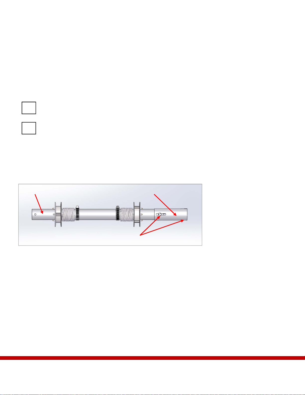
4.4 – Additional Drive Shafts
Step 1 – Install additional drive shafts by connecting neighboring shafts at the end by a coupler. See Figure 15
for an illustration of the coupler.
Step 2 – Bolt shafts together at the coupler with ¼-20 bolts. Keep the bolts as close to the center of the ¼-20
slots as possible.
Step 3 – Secure additional drive shafts by tightening all rotating plates on the support brackets.
Step 4 – If the section of drive shaft has a motor, align the sprocket on the drive shaft with the motor sprocket
as seen in Figure 16.
Step 5 – Verify the drive shaft can rotate freely in the support bracket by rotating it with your hand.
CouplerNon-coupler end
¼-20 bolt hole
Figure 15 – A short drive shaft section with a coupler to connect to other components.

20
Verify drive shafts are secure and can rotate freely
by hand.
Verify sprockets on motors and drive shafts are
aligned.
4.5 – Up Limit Switch
The Up Limit Switch is the sensor that alerts the M4000 when the Curtain is raised to its maximum level. The
Up Limit Switch is installed as a part of an assembly and attached to a support bracket on the Housing.
Step 1 – Attach the Up Limit Switch assembly to the same support bracket as the primary motor. See Figure 17
for more information on the mounting point.
Figure 16 – The motor sprocket and drive
shaft sprocket in proper alignment seen from
below
Figure 17 – (Left) the Up Limit Switch assembly and components. (Right) the Up Limit Switch mounting slots on the
support bracket.
Up Limit Switch mounting slots
Normally Open
Tang
Common
Primary motor
Critical alignment
Table of contents
Other Smoke Guard Firefighting Equipment manuals


Popular Firefighting Equipment manuals by other brands


Task Force Tips
Task Force Tips Masterstream Series Instructions for installation, operation and maintenance

STI
STI EZ-Path NEZ33R installation instructions

Tyco
Tyco 802SB installation instructions

Task Force Tips
Task Force Tips QuadraFog series Maintenance and service instructions

Tyco Fire Suppression & Building Products
Tyco Fire Suppression & Building Products ANSUL AQUASONIC Design, Installation, Recharge, and Maintenance Manual

TFT
TFT Monsoon Series Instructions for installation, safe operation and maintenance