Monitoring
Under normal conditions the Sensor, Sounder & Strobe devices
are monitored regularly and the data is used to create a
background performance record. When there is a potential event,
the Sensor, Sounder & Strobe device will flag the control panel
for attention. The control panel will take further readings from the
device and compare all the measurements with patterns and
rules to determine if it is a fire event.
Device functionality
All Sensor, Sounder & Strobe devices are monitored periodically
to check if they are working correctly, an indication of a fault is
given if there is a failure. For example the infrared signals
through the optical chamber is regularly checked, the thermistor
is checked for failure. The strobe and sounder circuits are
monitored for failure.
Heat sensor (H)
The heat sensing is provided by a thermistor. The temperature at
which the device goes into fire is defined by the configuration
settings in the control panel. The control panel also calculates
any rate of rise elements required in the fire decision.
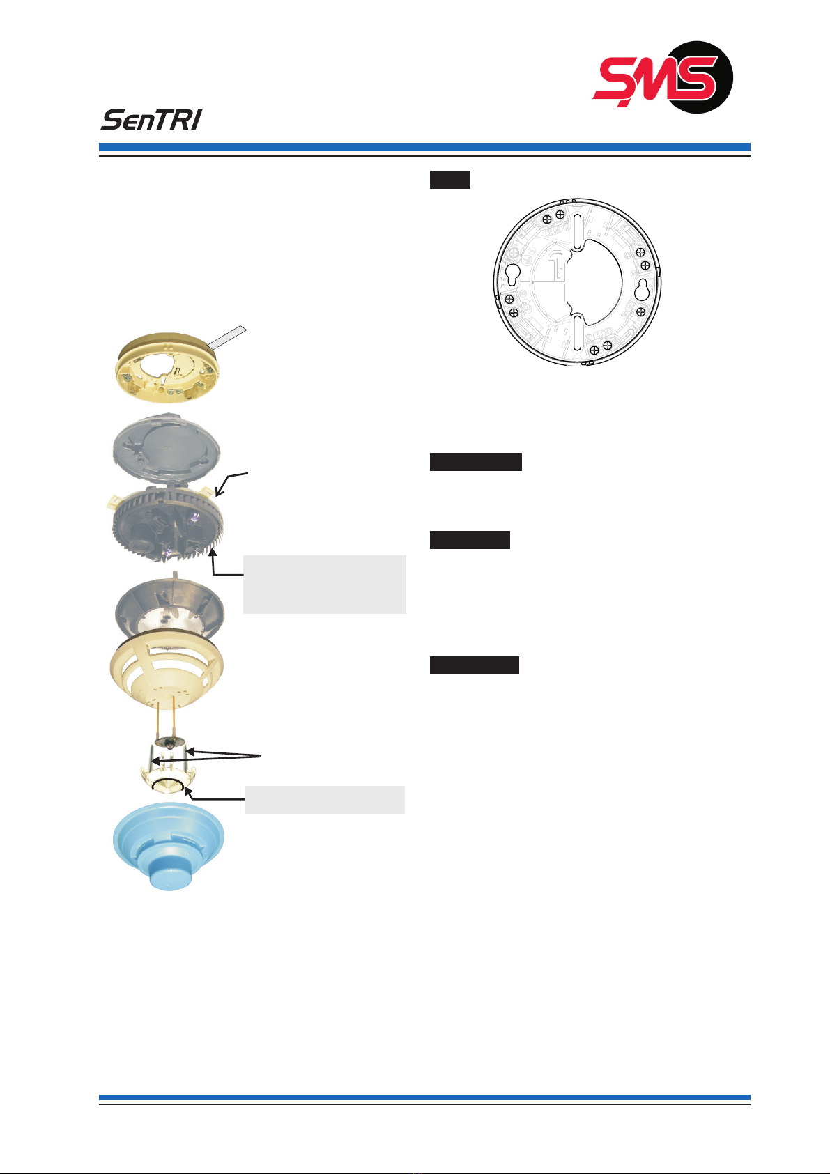
Optical sensors
Single Optical Sensor
The optical sensing is performed in the optical chamber using
transmitting LED 1 and an infrared receiver. Measurements are
taken at regular intervals. The control panel uses these readings
to detect the presence of smoke.
Bell tone
The bell tone function is stored on a flash memory chip within the
assembly of Sensor, Sounder & Strobe device .
Message 1 Bell tone
Sounder (S)
The sounder function in a Sensor, Sounder & Strobe device is
designed to meet the requirement of EN54 : Part 3. The EN54 :
Part 3 average output from the sounder is 85dBA at 1m or
75dBA at 3m at a bedhead, making it suitable for installation in
hotel bedrooms. The sounder can operate a turbo mode if
configured during commissioning to provide further 3dB output.
The sound outputs are based on the settings of the FABs and
SABs at the panel that gives changing levels over 2 seconds
duration in 8 time slots. The standard outputs are synchronised
with the S3devices installed in the same system.
A piezo disk within a Sensor, Sounder & Strobe device assembly
outputs the sound via a horn, which is constructed in the
chamber moulding. The volume of the sound output can be
individually set at the device, note that the sound level should not
be set lower than 65dBA at 1m for standards compliance. The
system prevents adjustment of volume down to zero. Another
feature that can be configured is the soft start that ramps the
sound volume gradually to the maximum level set at the device.
The Sensor, Sounder & Strobe device will have a white baffle to
identify it as having Sound functionality.
"The Sound Pressure Level at 90°will far
exceed the more useful average Sound Pressure Level
quoted.
Strobe (St)
The Strobe utilises a high-power red LED that receives its power
from a super capacitor in the Sensor, Sounder & Strobe device
assembly. The high light output from the LED is made possible
by the low impedance of the capacitor. When compared with the
conventional Xenon flasher the Sensor, Sounder & Strobe
device, the strobe outputs a lower level of light over longer
duration to achieve the same intensity. The strobe is designed for
installation on a ceiling and provides a wide viewing angle to
allow the light to be seen all around. As factory set the strobe
provides a pulsed output every 2s with signal 1, 1 second with
signal 2 and 1 second with signal 3, however the operation of the
strobe with the signals 1, 2 and 3 can be changed at the
commissioning stage. The strobe is synchronised with any
S-Cubed strobe installed in the same system.
The Disability Act 1995 recommends visual alarms, like the
Strobe when installed in the protected premises to warn
occupants who are hard of hearing.
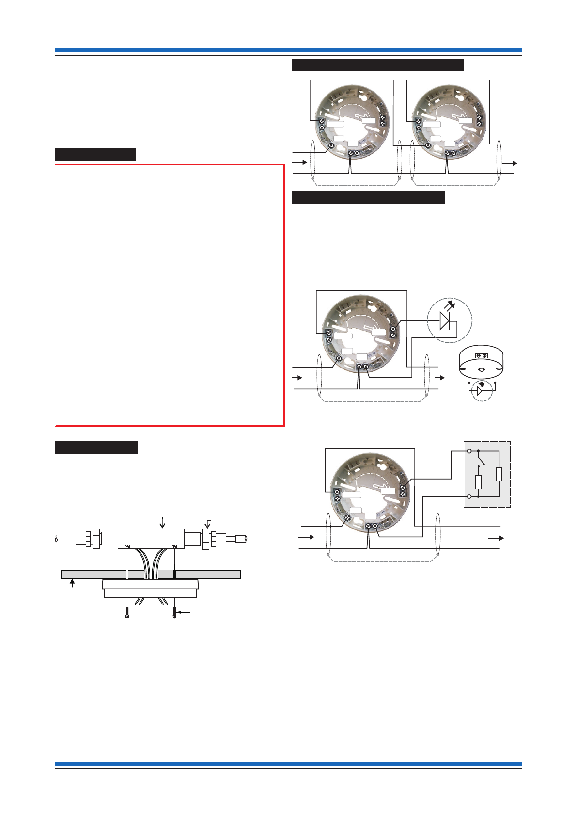
A metal back box must be used for surface and semi-flush
mounting and earth continuity must be maintained throughout the
whole loop. The earth must be securely connected to the metal
back box.
Description & Commissioning Sensor, Sounder & Strobe
2 4188-897 issue 3_12/13_SenTRI Sensor Data_PART-2
Transmitter
LED1
Receiver
Optical Chamber