2
STEP 2
INSTALL FRONT TIRES
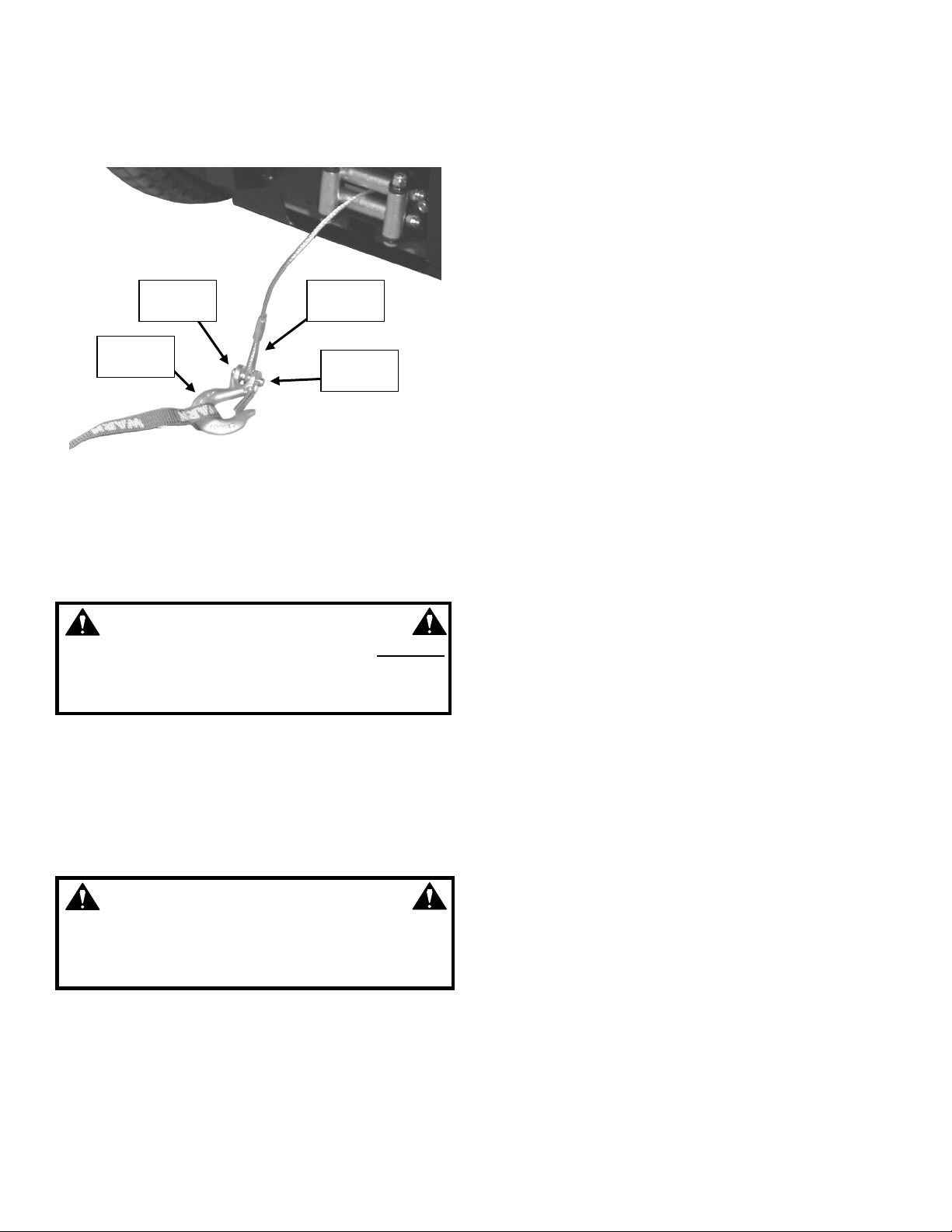
(NOTE: The front bumper can be used to lift the front of
the machine.)
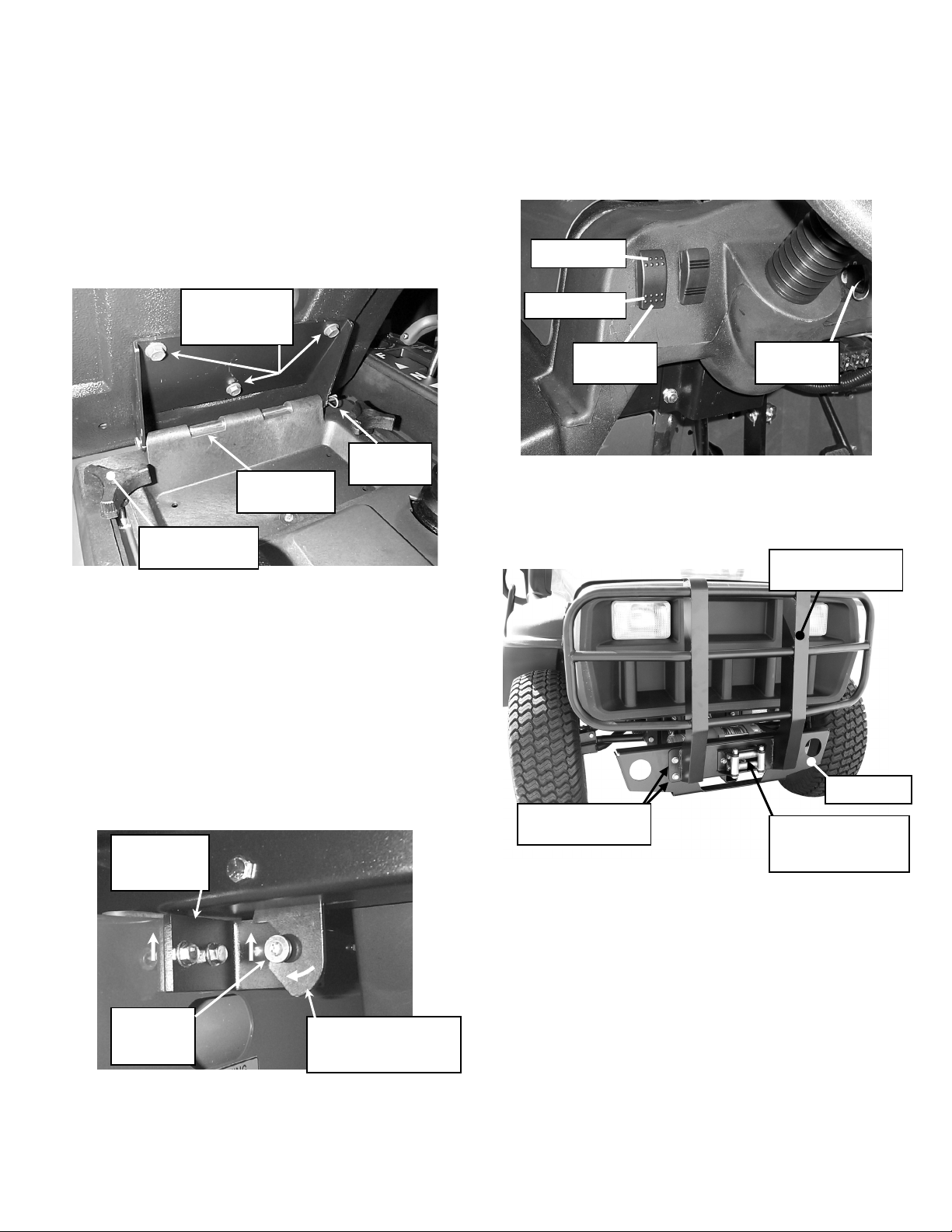
1. Loosen (do not remove) the two lug nuts securing
each support plate to the left and right front wheel
hubs. See Figure 1.1.
2. Remove the hardware securing the support plates
to the crate bottom.
3. Lift front of machine only high enough to install front
tires. Block machine securely to prevent it from
falling. Remove lug nuts loosened in operation #1
of this assembly step, and remove and discard
support plates. Set lug nuts aside for future
operation.
4. REMOVE OPERATOR PROTECTIVE STRUCTURE
FROM CRATE BOTTOM AT THIS TIME.
5. Check front wheel hubs to insure that they rotate freely.
Also check to make sure that the castle nuts are tight,
and the cotter pins are inserted fully and have at least
one leg bent back to secure in place.
6. Install left and right front tires (valve stems facing
outward) and secure each with 5 lug nuts (including
lug nuts removed in previous operation). NOTE for
Trail Cruisers only: Tires are directional. Install with
points of the chevron treads pointing forward. See
Figure 1.2.
7. Remove blocks and lower machine.
8. Torque lug nuts to 75 ft-lbs, using sequence shown
in Figure 1.2.
9. Install dust caps onto front wheel hubs.
STEP 3
ADJUST TIRE PRESSURE
IMPORTANT! Correct tire inflation pressure is critical to
the proper handling and braking of the machine.
1. Using a low-pressure tire gauge, check tire
pressure.
2. Adjust tire pressure to 15 psi. front and rear as
needed.
STEP 4
INSTALL OPERATOR PROTECTIVE
STRUCTURE (OPS)
NOTE: Assistance is required when installing the
Operator Protective Structure.
WARNING
Operator Protective Structure must be installed and
all mounting hardware tightened securely before
starting or operating machine.
WARNING
Do Not modify the OPS in any way before, during or
after installation. Modifying the OPS can result in
serious injury or death.
1. Locate and identify OPS mounting hardware –
twelve 3/8-16 x 1” carriage bolts and twelve 3/8-16
nyloc nuts. Place six of each on either side so they
will be in easy reach when attaching OPS to frame.
2. With assistance, raise OPS to vertical position and
orient structure so that the “WARNING” decal,
located on the side of the OPS, is on the right
(passenger) side of the machine.
3. Align holes in OPS with corresponding holes in
frame. Get one carriage bolt started on each side.
NOTE: Insert bolt from inside, as shown in Figure
1.3. Secure with 3/8-16 nyloc nut. Do not tighten at
this time.
FIGURE 1.3
4. Install remainder of bolts as per operation #3 in this
step, securing each with a nyloc nut.
5. Torque all OPS mounting hardware to 30-35 ft-lb.
NOTE: ALL OPS hardware must be properly
torqued to prevent inadvertent loosening and
subsequent failure of structure in a rollover.
6. Attach upper and lower heat shields to OPS using
two 5/16-18 self-tapping bolts. Do not tighten at this
time.
7. Attach side tabs of lower heat shield to left and right
frame rails using two 5/16-18 x 7/8” bolts and two
5/16-18 nyloc nuts.
8. Tighten all heat shield hardware securely.
CARRIAGE
BOLTS (6 EACH
SIDE). INSTALL
FROM INSIDE.
LOWER HEAT
SHIELD
UPPER HEAT
SHIELD
HEAT SHIELD
HARDWARE (x2)
OPS