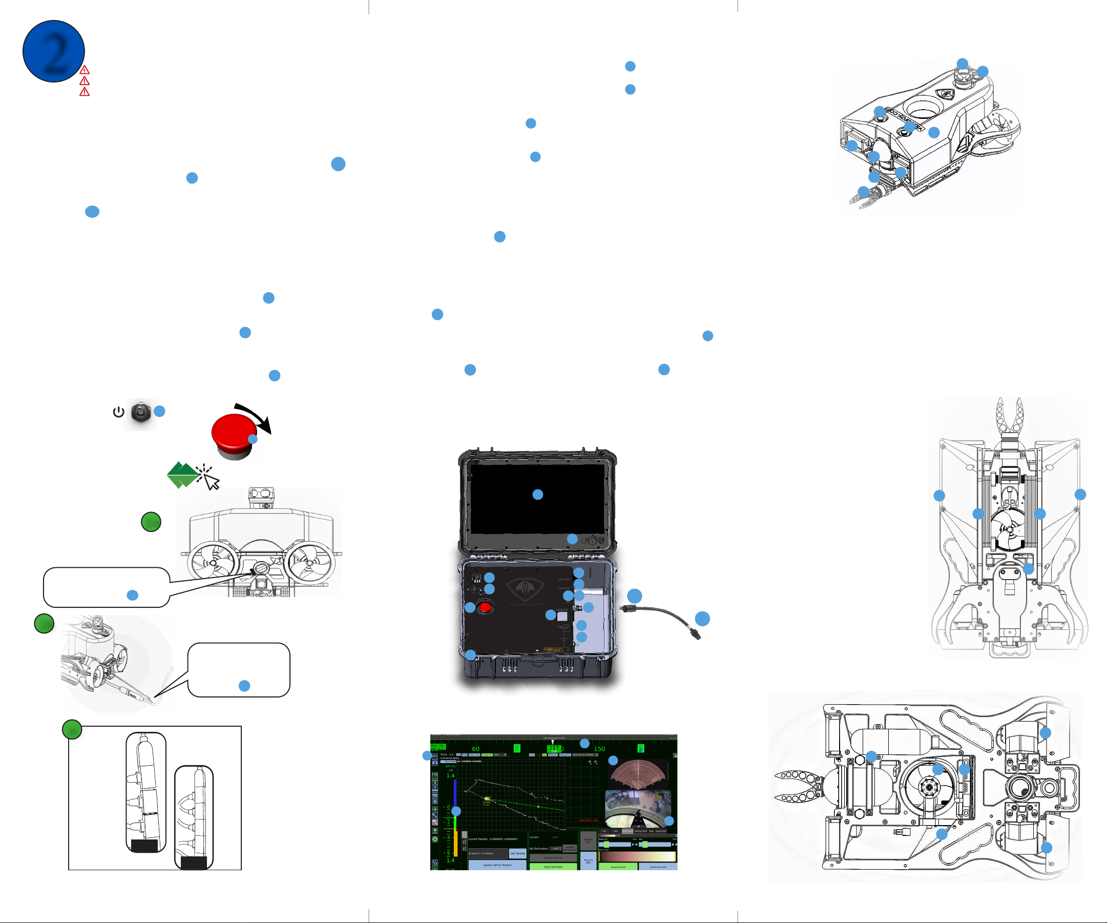
Test the strain relief to
verify the stress is on the
cable not the tether or
connector.
2A
2B
2C
BAD
31
32
GOOD
If the connectors
are separated,
do not place the
system in water.
Clean, lubricate
and reseat the
connectors.
35
1.
2.
3.
4.
5.
6.
7.
8.
9.
10.
11.
Aach the strain relief bolt
through the eye hole of the
strain relief cable. 34
2 Connecng & Powering On
Remove the tether caps and connect the female end of the tether and strain relief
to the ROV. See gure 2B. (Store caps in a secure locaon)
If not already connected, connect the male end of the double ended connector
to the Operator Control Console (OCC).
Connect the male end of the tether to the female end of the double ended
connector.
Remove the ROV oat block bolts and remove the oat block.
Inspect all 5-pin and 9-pin connectors to ensure they are seated and then
Replace and secure the oat block. See gure 2C. CAUTION: If the connectors are
not fully seated, clean, lubricate, and reseat them.
Connect the hand controller to the OCC controller USB port.
CAUTION: Do not connect more than one hand controller to the system at a me.
Connect the keyboard to the OCC keyboard USB port.
Conrm that the ROV POWER MAINS is fully depressed.
Connect the OCC power cord to the OCC and a power source.
Turn on the OCC.
Turn on the ROV POWER MAINS.
Twist the Red Power Mains buon clockwise.
Start the Pro 5 control soware.
WARNING:
CAUTION:
CAUTION:
Do not connect or disconnect cables while system is powered.
ALL ROV submerged connecons must be terminated.
Follow these steps in order when starng the system.
1.
2.
3.
4.
5.
6.
7.
8.
9.
10.
11.
12.
Connecng the System
ON
Pro 5
24
25
20
1
Pro 5 Component Idencaon
Float part number 70779
USBL Beacon --(oponal) part number 70693
LED Lighng Module part number 70023 (QTY 2)
Rotang Manipulator part number 70824
HD Camera Module part number 70044
Mulbeam 750D Sonar part number 71047
Vercal Thruster part number 70503
Port Thruster part number 70503
Starboard Thruster part number 70503
Pro 5 Power and Comms Module part number 71006
AHRS Module part number 70273
Ballast part number 71044
Serial Number Plate
Float Block Screw
Operator Control Console (OCC) part number 70218
High Denion Display
Display Brightness
Universal Power Plug 100-124 volts AC
OCC Power On|O Switch
ROV Power Mains/Emergency Stop
Line Insulaon Monitor
HDMI Ports
1.
2.
3.
4.
5.
6.
7.
8.
9.
10.
11.
12.
13.
14.
15.
16.
17.
18.
19.
20.
21.
22.
Auxiliary Ethernet Port
Controller USB Port
Keyboard USB Port
Tether Whip Connecon
26A-26B. Tether Double Ended Connector
Auxiliary 12 Volts (5 amp max)
Accessory USB Ports
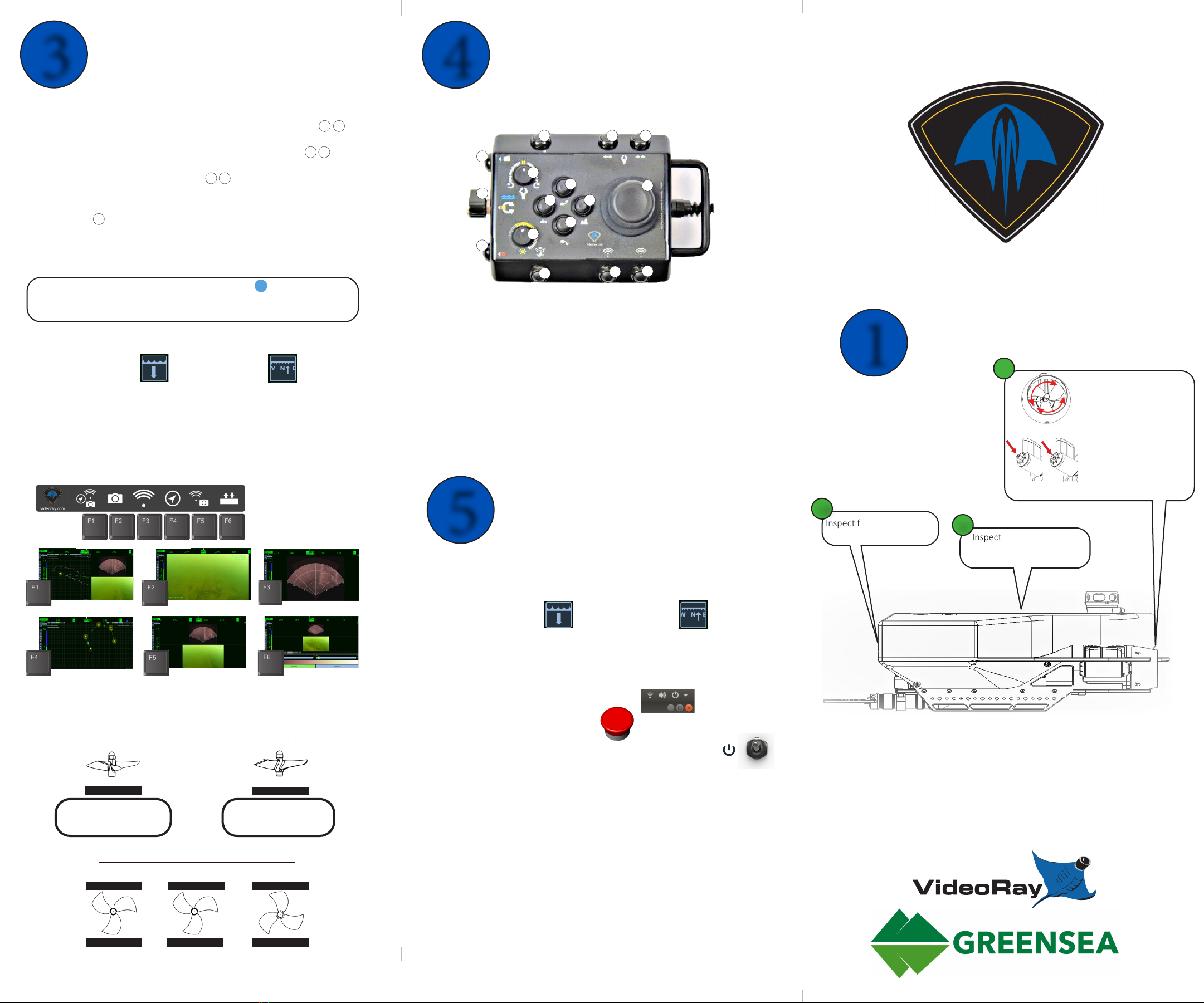
Compass Bar
Depth and Altude Tracker
Sonar feed
Video feed
Record buon
Strain relief bolt
Test strain relief
23.
24.
25.
26.
27.
28.
29.
30.
31.
32.
33.
34.
35.
Boom view
Top view
30
6
1
1
1
2
3
4
7
8
9
10
11
12
13
1
14
14
14
3
5
12
10
9
8
29
Greensea Soware
Heading - The Compass Bar will turn green when connected.
Depth - The Depth Tracker will turn green when connected.
Sonar - Imagery will display in the sonar window
when the sonar has connected.
Video - Imagery will appear in the video window
when the camera has connected.
13.
14.
15.
16.
Verify System Connecvity
USBL Installaon
NOTE: The USBL is an oponal accessory
NOTE: If not using the USBL, make sure the ROV connector port is sealed
Remove the oat block.
Feed the USBL accessory cable through the GPS hole in the oat block.
Connect the accessory cable to the power / communicaons module port.
Replace the oat block and secure the USBL beacon using the rear oat block
screw.
Connect the Topside GPS Antenna to one of the Accessory USB Ports on the OCC.
Connect the USBL Topside Staon to the OCC by plugging it into the Auxiliary 12 V
Port for power and the Accessory USB Port for communicaons.
Deploy the USBL Topside Staon in the water.
17.
18.
19.
20.
21.
22.
23.
29
30
31
32
15
17
18
20
21
22
23
24 25
26
27
28
19
16
The OCC
19
14
26A
26B
26A
26B
26
27 28
18
28
33