manuals.online logo
Brands
  1. Home
  2. •
  3. Brands
  4. •
  5. Snapper
  6. •
  7. Lawn And Garden Equipment
  8. •
  9. Snapper 1691530 User manual

Snapper 1691530 User manual

INSTALLATION
INSTRUCTIONS
MFG. NO. 1691530
HORN KIT FOR
FRONT-CUT RlDERS
Mounting configuration
for Hvdro units onlv.
Figure
1.
Ref.
Pati
NO. NO.
my.
Description
A
8
C
D
E
F
G
H
I
J
K
L
M
N
0
P
1679968
1930641
1921969
932747
1931277
1927477
1700095
1700094
1605761
1879959
1700643
1
1
1
1
1
1
1
1
1
1
1
2
2
2
1
1
HORN ASSY., (Included in Ref. No. K)
NUT, Flange Whizlock,
l/4-20
CAPSCREW, Hex.
1/4-20x
5/8
TIE, Cable
NUT, Flange Whizlock,
5/16-l
8
CAPSCREW. Taptite, 5/16-18x 1.00
WIRE ASSY..
(Blackl
WIRE ASSY. (Red)
CONNECTOR, Wire, Self-Stripping
HORN BUTTON ASSY. (Included in Ref. No.
K)
HORN &
8UlTON
ASSY. (Incl. Ref.
,Nos.
A &
J)
MOUNTING PLATE (Included in Ref. No.
A)
LOCKWASHER (Included in Ref. No. A)
NUT (Included in Ref. No. Al
SCREW (Included in Ref. No.
A)
L-BRACKET (Included in Ref. No. A)
1
FORM
-
1702038
PRINTED IN U.S.A.
8710
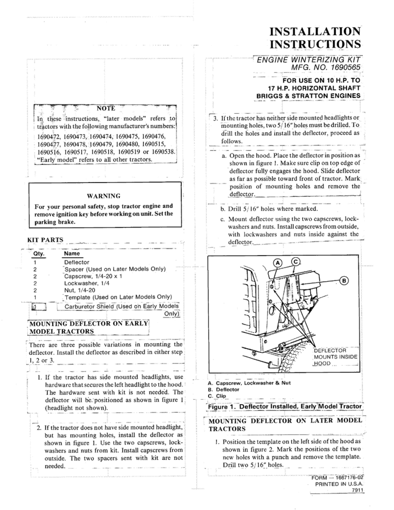
NOTE
Not all hardware supplied with horn kit will be used
for this installation. Discard excess hardware.
Refer to figure 1 to familiarize yourself with the
assembly.
NOTE
On newer gear models, battery is not located in rear
compartment (see figure 3). This allows installation
by either of the following methods.
HORN INSTALLATION -Early Gear Models
1.
Install the two mounting plates (A, figure 2) together
and install onto the shift cable mounting bracket
using the
l/4
flange whizlock nut and l/4-20
x
5/8
capscrew (B).
2.,
Mount the horn by inserting it through the mounting,
plates (A) and installing lockwasher and nut (D).
Then, connect one end of the 45 inch black wire to,
either horn terminal (C).
Figure 2.
A. Mounting Plates
6.
capscrew
C. Terminal
D. Nut
3. Route the 45 inch wire along with other wires along
right-hand side of frame and under footrest (figure
3).
4. Go to HORN BUTTON INSTALLATION
-
All
Models.
Figure 3. Early Gear Models
A. Horn
B. Wire
HORN INSTALLATION -Hydra Models
1.
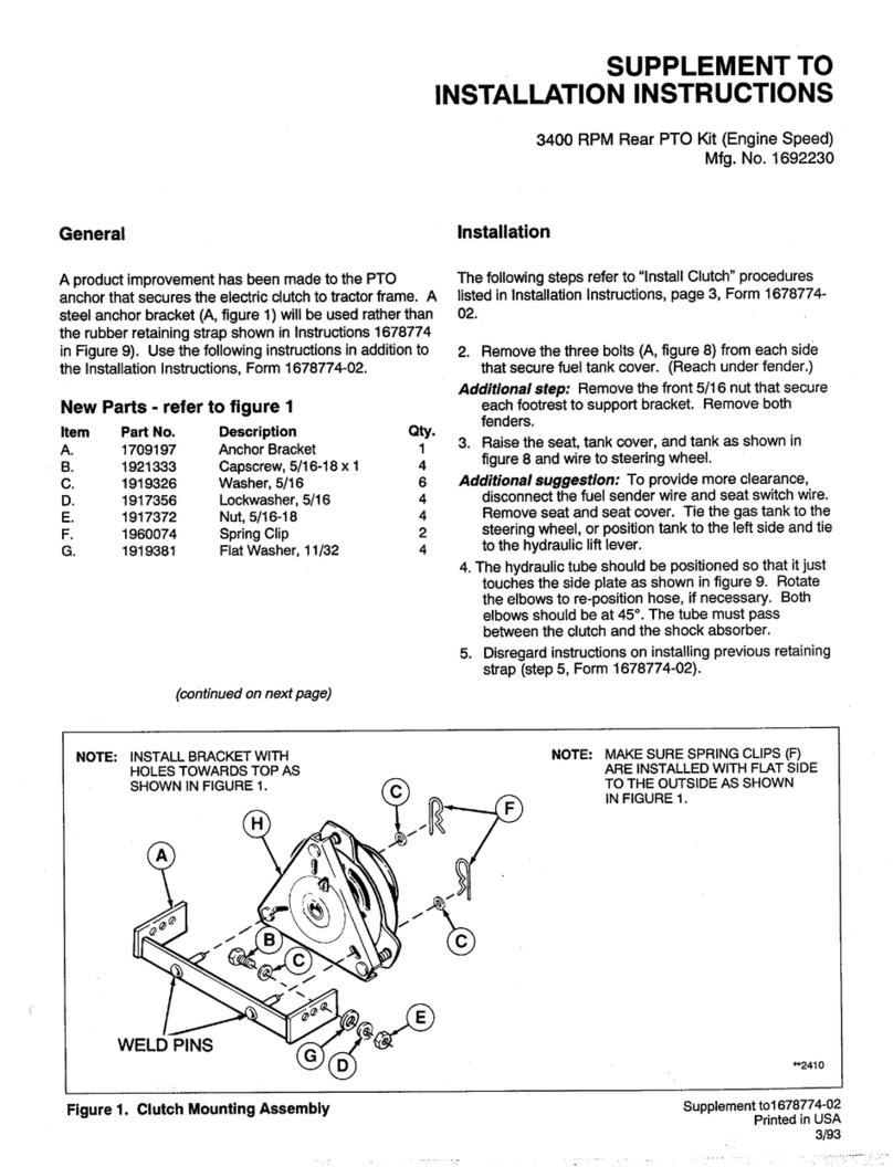
Connect the horn (A, figure 1) to the mounting plates
(L) with lockwasher (M) and nut (N).
2. Connect the L-bracket (P, figure 1) to the mounting
plates (L) with lockwasher (M) and nut (N).
3. Install the horn as shown in figure 4 as follows.
a. Locate the existing screw and retainer under the
rear edge of footrest.
Figure 4. Hydra ModelsFigure 4. Hydra Models
A. HornA. Horn
B. Mounting StrapsB. Mounting Straps
C. WireC. Wire
D. TerminalD. Terminal
2
b. Remove this existing screw, and install new 5/ 16-
18 x1 screw
(F),
being sure the retainer is in
original position.
c. Place the horn assembly into position onto the
screw and install the flange whizlock nut(E). The
horn should appear as in figure 4.
4. ,Connect the 45-inch wire(C) to either horn terminal
CD).
Route the wire, under the footrest as shown.
5. Go to HORN BUTTON INSTALLATION
-
All
Models.
HORN BUTTON INSTALLATION
-
All Models
1.
Remove the dash plate (A, figure 5) by removing six
screws (B). Disconnect plug from ignition switch.
2. Drill a
Il/
16 inch hole in the dash plate to install
horn button (C, figure 5) (shown installed). Measure
2 inches down from center of ignition switch. Then
measure
314
inch to left. Drill hole at that point.
3. Install the horn button in the hole by inserting the
button and securing with nut. Be sure terminals point
down before tightening nut.
Figure 5.
A. Dash Plate
6.
screws
(6)
C. Horn Button
D. Light Switch (Optional)
4. Route the 45-inch black wire (A, figure 6) up into
steerine column
thmuah
hole in frame.
Figure 6.
A. Wire
5. Connect the 45 inch black wire to either terminal of
the horn button.
6.
Connect the red wire supplied with kit onto the other
terminal of the horn button.
7. In this step, you will be connecting the red wire
installed in step 6 to an existing red wire that goes to
the ignition switch, using the self-stripping connector
supplied with kit.
a. Notice that in one terminal of the ignition switch
plug, there is a red and violet wire (this is the “L”
terminal marked on switch). This is the red wire
you’ll be using.
b. Notice that the self-stripping connector has one
hole that does not go all the way through. Insert
red wire installed in step 6 into thii hole. Then,
place the wnnector onto the red wire from
ignition switch and press closed with a pliers (red
wire will extend out both ends of connector.)
8. Install the plug onto ignition switch. Install the panel
’
with the six screws.
9. This completes the installation.

Other Snapper Lawn And Garden Equipment manuals

Snapper 1692376 User manual

Snapper

Snapper 1692376 User manual

Snapper 21SST User manual

Snapper

Snapper 21SST User manual

Snapper 1690729 User manual

Snapper

Snapper 1690729 User manual

Snapper 1691765 User manual

Snapper

Snapper 1691765 User manual
Snapper 1691003 User manual

Snapper

Snapper 1691003 User manual

Snapper THATCHERIZER 6-0948 Installation and operation manual

Snapper

Snapper THATCHERIZER 6-0948 Installation and operation manual

Snapper 990147 User manual

Snapper

Snapper 990147 User manual

Snapper 1691531 User manual

Snapper

Snapper 1691531 User manual

Snapper FM7300 Operation and maintenance manual

Snapper

Snapper FM7300 Operation and maintenance manual

Snapper 690179 User manual

Snapper

Snapper 690179 User manual

Snapper 6-0990 Guide

Snapper

Snapper 6-0990 Guide

Snapper 1690681 User manual

Snapper

Snapper 1690681 User manual

Snapper CPSC5.5 User manual

Snapper

Snapper CPSC5.5 User manual

Snapper 1690624 User manual

Snapper

Snapper 1690624 User manual

Snapper TA 520 Operation and maintenance manual

Snapper

Snapper TA 520 Operation and maintenance manual

Snapper 6-1014 User manual

Snapper

Snapper 6-1014 User manual

Snapper 1690785 User manual

Snapper

Snapper 1690785 User manual

Snapper Thatcherizer 61256 Installation and operation manual

Snapper

Snapper Thatcherizer 61256 Installation and operation manual

Snapper 6-1811 User manual

Snapper

Snapper 6-1811 User manual

Snapper 2-9693 Manual

Snapper

Snapper 2-9693 Manual

Snapper 7063344 User manual

Snapper

Snapper 7063344 User manual

Snapper Clean Sweep Triple Catcher User manual

Snapper

Snapper Clean Sweep Triple Catcher User manual

Snapper 1690565 User manual

Snapper

Snapper 1690565 User manual

Snapper Thatcherizer 63120 Installation and operation manual
Snapper

Snapper Thatcherizer 63120 Installation and operation manual

Popular Lawn And Garden Equipment manuals by other brands

EMGA Mo-el 505.350 Use and maintenance

EMGA

EMGA Mo-el 505.350 Use and maintenance

Craftsman 358.795781 instruction manual

Craftsman

Craftsman 358.795781 instruction manual

Espina XTP115A instruction manual

Espina

Espina XTP115A instruction manual

juwel 20469 Mounting instructions

juwel

juwel 20469 Mounting instructions

Sunnydaze Decor XCA-115 manual

Sunnydaze Decor

Sunnydaze Decor XCA-115 manual

FRAME IT ALL 800002123 manual

FRAME IT ALL

FRAME IT ALL 800002123 manual

Koolatron MK12 owner's manual

Koolatron

Koolatron MK12 owner's manual

greenhouse sensation Solargrow instructions

greenhouse sensation

greenhouse sensation Solargrow instructions

Ryobi RLM36X46S240 Original instructions

Ryobi

Ryobi RLM36X46S240 Original instructions

Schiller RYAN MATAWAY 744283C Setup manual

Schiller

Schiller RYAN MATAWAY 744283C Setup manual

AL-KO MULTITOOL MT 40 Instructions for use

AL-KO

AL-KO MULTITOOL MT 40 Instructions for use

Strend Pro 111226 instruction manual

Strend Pro

Strend Pro 111226 instruction manual

Toscana MINI DLE Instructions for use and maintenance

Toscana

Toscana MINI DLE Instructions for use and maintenance

Troy-Bilt Bronco CRT Service manual

Troy-Bilt

Troy-Bilt Bronco CRT Service manual

Echo PAS-260 PRO - 01-07 Operator's manual

Echo

Echo PAS-260 PRO - 01-07 Operator's manual

VOUNOT 2500D quick start guide

VOUNOT

VOUNOT 2500D quick start guide

Craftsman 650 Series owner's manual

Craftsman

Craftsman 650 Series owner's manual

SNOWJOE AQUAJOE AJSGH25-RM instructions

SNOWJOE

SNOWJOE AQUAJOE AJSGH25-RM instructions

manuals.online logo
manuals.online logoBrands
  • About & Mission
  • Contact us
  • Privacy Policy
  • Terms and Conditions

Copyright 2025 Manuals.Online. All Rights Reserved.