Snow Performance 20010 User manual

© 2009, Snow Performance, Incorporated
INSTALLATION INSTRUCTIONS
FOR PART #20010
WATER / METHANOL INJECTION
SYSTEMS

© 2009, Snow Performance, Inc
CONTENTS
Kit Contents.........................................................................3
Introduction.........................................................................4
Nozzle Identification Chart:................................................4
Installation – Mechanical....................................................5
Installation - Electrical......................................................10
Variable Controller Installation........................................10
Variable Controller Tuning...............................................11
Controller Operation Example.........................................11
Testing the System...........................................................12
Tuning Quick Reference...................................................13
Fluid Level Switch.............................................................15
Solenoid Upgrade (optional)............................................16
Install Notes.......................................................................17
Warranty……………………………….………………………18
Contact Us…………………………………………………….21
Have a question?
Technical FAQ: www.snowperformance.net/faqs.php
CAUTION
You must completely read though these instructions before
installing and operating this product. Failure to due so can
result in damage to this product and the vehicle.

© 2009, Snow Performance, Inc
Kit Contents
Parts
oSHO (Special High
Output) Pump
o3 Qt Reservoir
o10 ft High Pressure
Tubing
o3 ft Black Wire Loom
oInstallation Instructions
Electrical Packet
o1 Green LED
o2 Blue Butt Connectors
o3 Small Eyehooks
o1 Male Connector
o1 Female Connector
o1 Vacuum “T”
oVC-25/MAF Controller
With Harness
o10 Tie Wraps
Required Tools
Electric Drill w/ Drill Bits
Utility Knife
Screwdriver – Phillips
Assorted Wrenches
1/8” – 27 NPT Tap
Mechanical Packet
o1 Nozzle Holder
o1 3/8” NPT – ¼” Tube
Straight Fitting
o7 #8x1&1/2” Screws
o4 #8 Washers
o4 #6x1/2” Screws
o18” 1/8” Silicone Tubing
o1 E-6000® (GOOP)
Nozzles
o60ML/MN (Yellow)
o100ML/MN (Black)
o175ML/MN (Green)
o225ML/MN (Purple)
o375ML/MN (Red)
o625ML/MN (Blue)
Upgrades
oBulkhead
o2.5 Gallon Reservoir
oSolenoid
oHose Adaptor or Bung
oLevel Switch
oSafeInjection®
oNitrobooster®
oDual Nozzle
oCarburetor Plate
oBoost Juice
© 2009, Snow Performance, Incorporated
Introduction
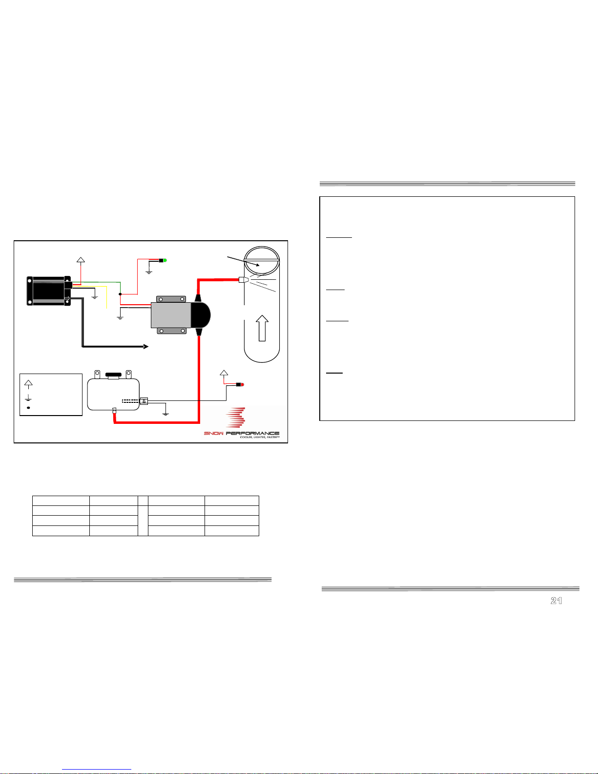
-Please refer to system diagram during install. The optional Level
Switch Upgrade (#40030) is shown.
Nozzle Identification Chart:
Nozzle Color Nozzle Size Nozzle Color Nozzle Size
Yellow 60 ml/min Purple 225 ml/min
Black 100 ml/min Red 375 ml/min
Green 175 ml/min Blue 625 ml/min
Low Fluid LED
Red
Black
Black
Green
Red
Red
White
Red
Black White
Black
To Boost Source
Pump
Injection Status LED
Air Flow
Throttle Plate
+12 Volt Key On
Engine Ground
Wire Connection
Yellow
Not Used
© 2009, Snow Performance, Inc
Contact Us:
Phone
Office (719) 633-3811
Fax (719) 633-3496
Tech Support Line (Toll Free) (866) 365-2762
Web
http://www.snowperformance.net
Email
sales@snowperformance.net
customerservice@snowperformance.net
tech@snowperformance.net
Mail
Snow Performance, Inc
1017-A East Highway 24
Woodland Park, CO 80863
Notes
The contents of this document are subject to change without prior notice.
No part of or this entire document may be reproduced in any form
without prior written permission of Snow Performance, Inc under the
copyright except for private use.
The names, addresses and telephone numbers mentioned are current as
of July 1, 2009. Note that this information is subject to change. Please
refer to www.snowperformance.net for current information.

© 2009, Snow Performance, Inc
LIMITATION OF LIABILITY
REPAIR OR REPLACEMENT OF A DEFECTIVE PRODUCT IS
THE ORIGINAL RETAIL PURCHASER’S EXCLUSIVE
REMEDY UNDER THIS WARRANTY.
DAMAGE OR INJURY TO THE ORIGINAL RETAIL
PURCHASER, TO HIS OR HER VEHICLE, CARGO, OR
PROPERTY, AND/OR TO ANY OTHER PERSON OR
PROPERTY IS NOT COVERED BY THIS WARRANTY.
THIS WARRANTY IS EXPRESSLY MADE IN LIEU OF ANY
AND ALL OTHER EXPRESS WARRANTIES, WHETHER
ORAL OR WRITTEN. SNOW’S SOLE LIABILITY IS LIMITED
TO THE REMEDY SET FORTH ABOVE. IN NO EVENT WILL
SNOW BE LIABLE FOR ANY DIRECT, INDIRECT,
CONSEQUENTIAL, INCIDENTAL, SPECIAL, EXEMPLARY,
OR PUNITIVE DAMAGES OR FOR ANY OTHER DAMAGES
OF ANY KIND OR NATURE (INCLUDING, BUT NOT
LIMITED TO, LOST PROFITS OR LOST SALES). SOME
STATES DO NOT ALLOW THE EXCLUSION OR
LIMITATION OF INCIDENTAL OR CONSEQUENTIAL
DAMAGES, SO THE ABOVE LIMITATIONS MAY NOT
APPLY TO YOU.
Non-Warranty Repair/Retest
Products returned due to damage or misuse and Products retested
with no problem found are subject to repair/retest charges. Product
will be returned to customer at customer’s expense. A credit card
number must be provided in order to obtain an RMA (Return
Merchandise Authorization) number prior to returning Product.
© 2009, Snow Performance, Inc
Installation – Mechanical
Step 1 Reservoir Install
Install straight fitting and
mount reservoir as high in
engine compartment as
possible using #8x1½” sheet
metal screws and washers
provided. Note that the
nozzle should be the highest
point in the system.
Optional: The factory
windshield washer reservoir can be used as the reservoir for your
system.
•Drill 9/16” hole in desired bulkhead location.
•Remove one nut from bulkhead and turn the remaining nut until it is at
the very end.
•Feed red tubing through the drilled hole and up and out of the top of
the reservoir.
•Attach tubing to the bulkhead on the side opposite the nut.
•Pull the tubing through the bulkhead hole until the bulkhead seats
against the inside of the reservoir.
•Apply E6000® sealant (included) around bulkhead.
•Slide the nut you had previously removed up onto the tube and thread
onto bulkhead.
•While pulling firmly on the red tubing, tighten the outer nut using a
17mm socket (only needs to be hand tight). A ratchet is not needed.
•Once sealant has set, fill reservoir with water and check for leaks.
You can mount the tank in the rear of the vehicle.
The pump is a pusher type by design so it needs to
be mounted as close to the reservoir as possible. Because the
pump is oversized, injection pressure will not be affected. A
Solenoid Upgrade is recommended for rear mounted reservoirs.

© 2009, Snow Performance, Inc
Step 2 Pump Install
Mount the pump so the inlet is positioned at the lowest point of the
reservoir or lower. Pump can be mounted horizontally or vertically using
the supplied screws and washers. Ensure that no sharp bends in the
high pressure tube occur near the pump. Sharp bends can cause stress
on the inlet and outlet ports of the pump, causing leaks. Trim tube with a
utility knife or razor blade, making sure to eliminate any burrs or kinks on
the end. Insert firmly into the pump about ½ inch through the light grey
locking collar. Note the arrows indicating flow direction on the top of the
pump. To remove the hose, gently and evenly push the light grey locking
collar into the head unit of the pump, then pull on the hose gently.
Measure the distance from the reservoir outlet to the pump inlet. Cut the
¼” red tubing using utility knife. Make cuts are as square as possible.
Ensure there are no kinks in the tubing and insert tubing into quick
disconnects at pump and reservoir until fully seated. Keep the pump
within 2 feet of the reservoir.
Mount pump away from direct road spray and
debris.
© 2009, Snow Performance, Inc
This warranty does not cover problems caused by normal wear and
tear including aesthetic oxidation of surfaces, accidents, unlawful
vehicle operation, or modifications or repairs to product not
performed or authorized by Snow. This includes any product that
is disassembled or taken apart for any reason.
In addition, this warranty does not cover problems resulting from
conditions beyond Snow’s control including, but not limited to,
theft, misuse, overloading, or failure to assemble, mount or use the
product in accordance with Snow’s written instructions or
guidelines included with the product or made available to the
original retail purchaser.
In the event of failure, Snow will repair or replace the part at
Snow's sole discretion. Failures resulting from misapplication or
misuse of the Product, failure to adhere to any specifications or
instructions, or failure resulting from neglect, abuse, accidents, or
act of nature are not covered under this warranty.
Warranty service may be obtained by calling 866-365-2762,
getting an RMA (Return Merchandise Authorization), delivering
the part to Snow along with proof of purchase. Customer agrees to
insure the Product or assume the risk of loss or damage in transit,
to prepay shipping charges to Snow, and to use the original
shipping container or equivalent. Shipping for Warranty
replacement parts shipped outside the continental US will be
charged to customer.

© 2009, Snow Performance, Inc
Warranty
Snow Performance's commitment to providing the best
water/methanol systems is reflected in the components and
construction of all Snow Performance Boost Cooler® kits.
A lifetime warranty for injection systems is available with
exclusive use of Boost Juice™ injection fluid. The standard
warranty is 2-years from purchase and covers all Snow
Performance products and accessories purchased on or after June
1, 2009 manufactured by Snow Performance, Inc. (Snow). This
warranty terminates when the original retail purchaser sells or
otherwise transfers the product to any other person.
Warranty Policy
Snow Performance, Inc. warrants that the Product shall conform to
and perform in accordance with published technical specifications
and shall be free of defects in materials and workmanship
providing:
1. You are the original purchaser and provide proof of purchase.
2. For lifetime warranty, the Warranty Card that came with system
(not applicable to separate parts purchases) is returned to Snow
within 90-days of purchase. If valid warranty card not on file with
Snow, the standard 2-year warranty applies from date of purchase.
3. An RMA # has been attained and is displayed on package
containing returned part.
Subject to Snow’s inspection of the product, Snow will remedy
defects in materials and/or workmanship by repairing or replacing,
at Snow’s option, the defective product without charge for parts or
labor, subject to the limitations and exclusions described in this
warranty.
© 2009, Snow Performance, Inc
Step 3 Nozzle Selection
Nozzle sizing is a function of horsepower, which approximates the
engine airflow, and boost, which approximates intake charge heat.
Recommended starting points:
250 - 350 RWHP: 175 ml/min nozzle.
350 - 475 RWHP: 375 ml/min nozzle
475 - 600 RWHP 625 ml/min nozzle
Seal the nozzle into the nozzle holder using the
included E6000® sealant. Using a sealant that is
not permanent will allow for nozzle changes during tuning. Simply
remove the nozzle, clean the threads, and reinstall using sealant.
Assemble desired nozzle into nozzle holder using E6000® sealant. The
end of the nozzle with the fine mesh screen is to be inserted into
the nozzle holder. Torque ½ turn past finger tight. Do not use Teflon
sealants on Snow Performance fittings.
Correct Incorrect
NOTE: If nozzle is mounted lower then the reservoir, a Solenoid Upgrade
(#40060) must be used to prevent draining.
© 2009, Snow Performance, Inc
Step 4 Nozzle Mounting
The nozzle assembly should be installed 90° to the direction of airflow.
On round intake tubes, this is 360° around the tube meaning the nozzle
can be mounted in any direction. This will ensure maximum cooling as
the nozzle sprays in a cone pattern. Be sure that the nozzle is higher
than the reservoir to avoid siphoning.
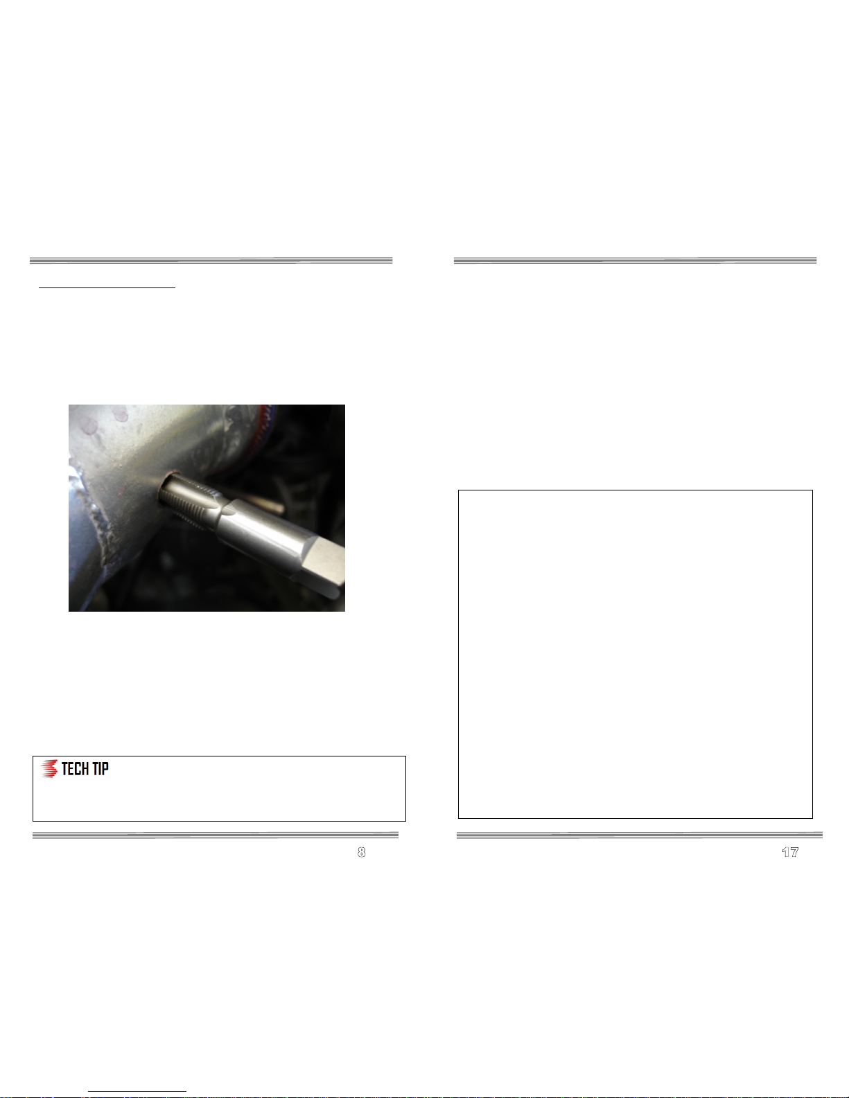
Drill and tap (11/32" pre-drill, 1/8”-27 NPT tap) air inlet tube as close as
possible to throttle body/throttle plate.
The nozzle is mounted using its external 1/8 NPT threads. Tighten the
nozzle and nozzle holder assembly one half turn past finger tight using
E6000® to seal the threads.
Carb Plates are available for 4150 and 4500 style square bore
carburetors.
You can mount the nozzle in a plastic or rubber air inlet tube using a
Nozzle Mounting Adapter (#40110). Weld-in aluminum (#40120) and
steel (#40130) are available.
The typical nozzle mounting point is before the
throttle body/plate. If you mount the nozzle after
the throttle body/plate (including the use of a carb spacer plate), a
Solenoid Upgrade (#40060) must be used to prevent siphoning at
idle.
© 2009, Snow Performance, Inc
Install Notes
Pump Setting ____________(psig)
Nozzle Size ____________(ml/min)
Boost / Vacuum setting _________
Misc:
Disclaimer
Do not use this product until you have carefully read the following agreement.
This sets forth the terms and conditions for the use of this product. The installation of this
product indicates that the BUYER has read
and understands this agreement and accepts its terms and conditions.
Performance products by their nature are designed to increase horsepower and
performance not engineered in the original vehicle and the increased stress could result in
damage to related systems. This is a high performance product – use at your own risk.
Snow Performance Inc., Its agents, employees or owners shall not be under any liability
whether in contract or otherwise whether or not resulting from our negligence or contents of
information supplied for any damage or loss resulting from such information.
The BUYER is responsible to fully understand the capability and limitations of his/her
vehicle according to manufacturer specifications
and agrees to hold the SELLER harmless from any damage resulting from failure to adhere
to such specifications.
The SELLER disclaims any warranty and expressly disclaims any liability for personal
injury or damages. The BUYER acknowledges
and agrees that the disclaimer of any liability for personal injury is a material term for this
agreement and the BUYER agrees to
indemnify the SELLER and to hold the SELLER harmless from any claim related to the
item of the equipment purchased. Under no
circumstances will the SELLER be liable for any damages or expenses by reason of use or
sale of any such equipment.
The BUYER is responsible to obey all applicable federal, state, and local laws, statutes,
and ordinances when operating his/her
vehicle, and the BUYER agrees to hold SELLER harmless from any violation thereof.
The SELLER assumes no liability regarding the improper installation or misapplication of its
products.
It is the installer's responsibility to check for proper installation and if in doubt, contact the
manufacturer.

© 2009, Snow Performance, Inc
Pump
Injection Status
LED
Red
Red
White
Green
from
Relay/S2 Harness
Black
Black
Black
Air Flow
Throttle Plate
Engine
Air Intake
IN CYL
Solenoid Upgrade (optional)
The optional Solenoid Upgrade (#40060a) is required if the nozzle is to
be installed after the intake throttle plate (as shown), or the fluid reservoir
is mounted higher then the nozzle. It is highly recommended for trunk-
mount reservoirs.
Finger thread the two 1/8” NPT quick connect fittings into ports labeled
IN and CYL on the solenoid. Tighten an additional half turn past finger
tight.
Cut high pressure line at location solenoid is to be installed. Insert ends
of cut line into quick connect fittings of solenoid. The port labeled IN is
the inlet and the port labeled CYL is the outlet. Gently pull on line to
check secure connection. If line pulls out, re-insert farther into fitting to
engage locking clips. If high pressure line removal is required, firmly
press in metal fitting ring to disengage locking clips while pulling hose
from fitting.
Connect one of the BLACK wires from solenoid to the RED positive
pump wire. Note that connecting the wire to any other power source
other then the pump wire will result in improper operation of solenoid.
Connect the second BLACK wire to a secure chassis ground location.
Or White from
S3 Harness
© 2009, Snow Performance, Inc
Step 5 Nozzle Connection
Measure the distance from the pump outlet to the nozzle holder. Cut the
¼” tubing using utility knife. Make cuts are as square as possible.
Ensure there are no kinks in the tubing and insert tubing into quick
disconnects until fully seated. Gently pull on tubing to ensure a good
connection.
Use tie wraps to help route tubing and to ensure it doesn't contact
moving or hot parts in the engine compartment. Have tubing connect to
quick connect fittings at shallow angles. Having an immediate sharp
bend may unseat the tubing from the internal o-ring and create a leak.
Continual insertion and removal from quick connect fittings will mar the
end of the tubing. Over time the internal gripping teeth may lose their
hold of the tubing which may create a leak. If this occurs simply remove
the tubing and make a fresh cut using a razor blade.
© 2009, Snow Performance, Inc
Installation - Electrical
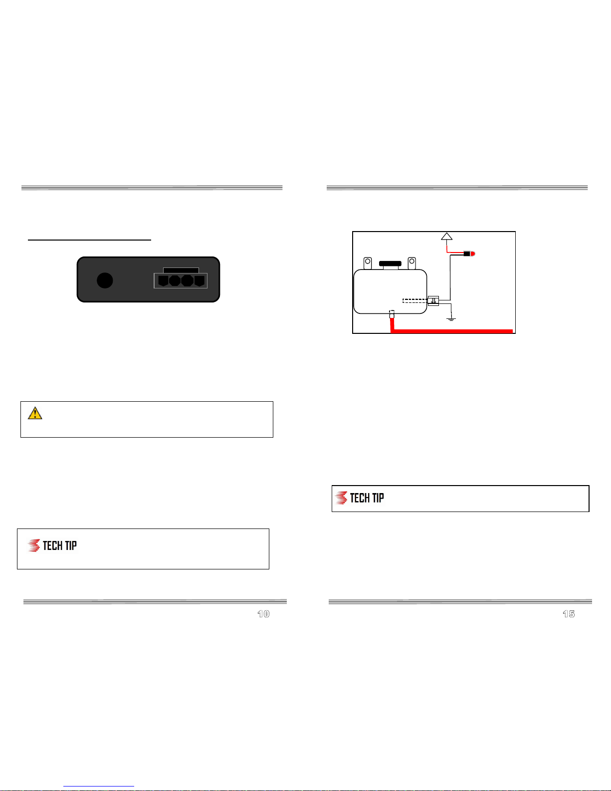
Variable Controller Installation
The figure above shows the back view of the variable controller. Attach
controller to secure location with easy access in engine bay or
passenger compartment. The VC series controllers are designed to
withstand engine bay conditions, but should not be mounted directly to
the engine block. Connect vacuum/boost hose from intake plenum to
hose barb on back of controller and secure with a tie wrap. Plug wire
harness into back of controller. Note the terminal positions are
numbered on the bottom side of wire harness connector.
CAUTION: Disconnect the negative battery terminal while
connecting wires to prevent electrical fire or damage to controller.
•Connect GREEN wire at position 4 to Pump RED power wire.
•Connect RED wire at position 3 to +12 volt key on source. When
selecting a 12V key on source, try to find a dedicated circuit fused for
10-15 amps.
•Connect BLACK wire at position 1 to a good ground location.
•The YELLOW wire at position 2 is not used in boost referenced
applications.
Always have a good electrical ground connection.
A poor ground will result in erratic operation of
controller.
1 2 3 4
© 2009, Snow Performance, Inc
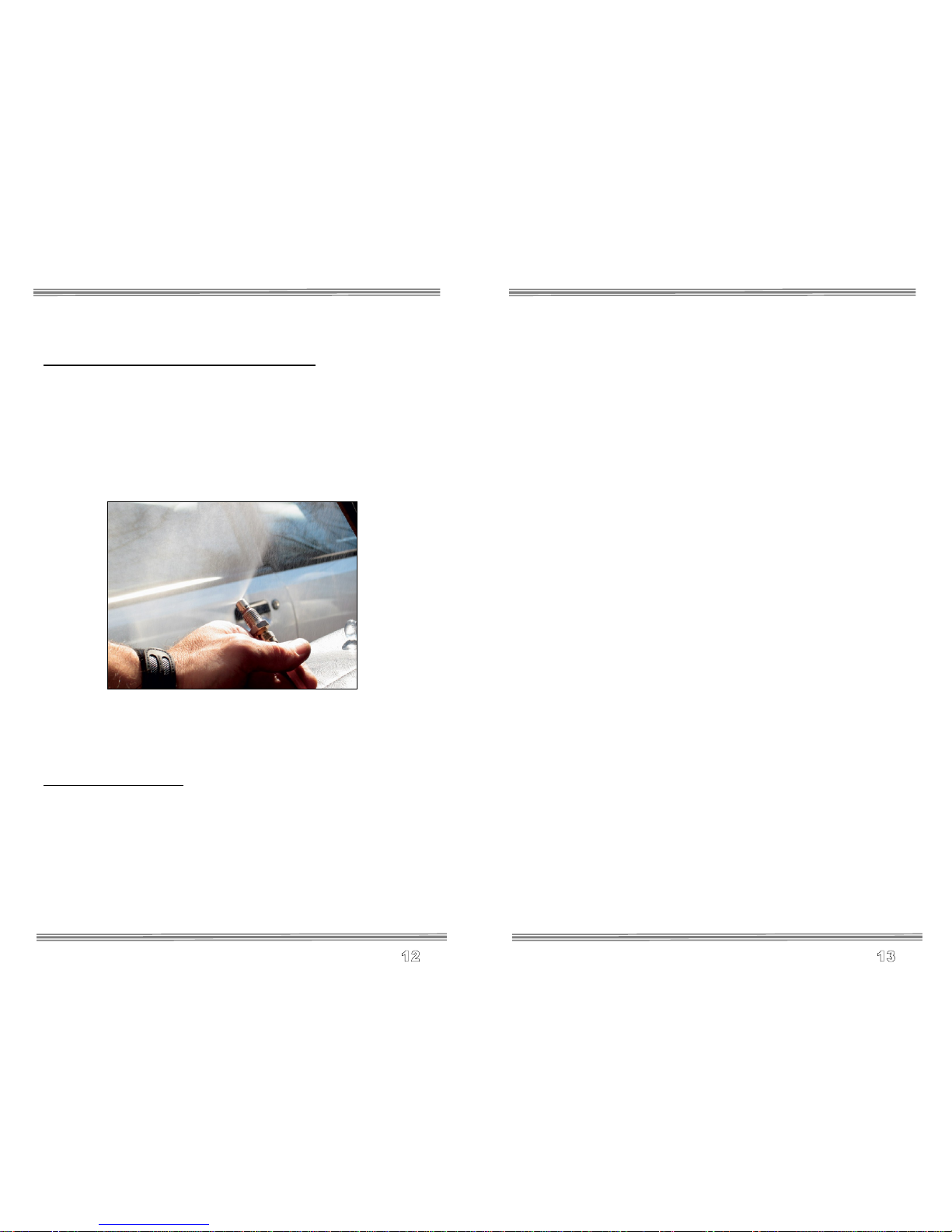
Fluid Level Switch
Instructions
•After mounting reservoir, mount red LED in dash. Next to the green
“injection” LED is usually easiest.
•Wire LED per diagram with Red wire to a 12v key-on source, and the
White wire to one of the Black wires of the level switch.
•Connect other Black wire of the level switch to vehicle ground.
•With key-on source enabled, the red LED should be “on” with no fluid
in the reservoir. Upon filling the reservoir, the red LED should be
“off”.
The level switch is designed to indicate when there
is less than 1” of fluid in the reservoir.
Low Fluid LED
Red
Black
Black

© 2009, Snow Performance, Inc
Maintenance – Remove nozzle(s) and clean screen filters at
least once per year using carb cleaner.
The Boost Cooler® has been designed to operate with high
concentrations of methanol. Oil or other additives are not required
for system lubrication.
For best performance, cooling, and system life it is recommend that
Snow Performance Boost Juice™ (#40008) be the exclusive fluid
used in the system.
© 2009, Snow Performance, Inc
Variable Controller Tuning
•Rotate the MODE switch
clockwise to select
BOOST mode.
•Adjust the START boost
level first by turning dial clockwise to ½ to 1/3rd the engines max
boost. This sets the boost pressure required to activate the injection
system.
•Adjust FULL dial to the maximum boost the vehicle can make.
•If bucking or bogging is experienced at the onset of injection,
increase the start point. If it is felt in the higher RPMs, increase the
full point. Often a full point below the vehicles max boost can be
used.
Controller Operation Example
The left arrow on the chart shows the START dial at 4 psi and the FULL
dial at 12 psi. At 4 psig of boost pressure the pump will operate at 10%.
At 12psig of boost pressure, the pump will deliver 100% of injection
pressure. For boost pressure readings between the START and FULL
settings, the controller will linearly adjust the pump pressure as shown on
the graph.
0
10
20
30
40
50
60
70
80
90
100
4 6 8 10 12 14 16 18
Boost Pressure psi
Start
Pump Output %
Full
© 2009, Snow Performance, Inc
Testing the System
Step 1 Test Pump and Mechanical System
Disconnect all control and SafeInjection® modules. Disconnect tube from
the outlet port of the pump. Using a 12 volt source, apply power to red
wire of pump. Pump should activate, green LED should go on, and fluid
level in tank should go down. It is recommended to also check the
nozzle spray pattern while following this procedure. Also check for leaks.
Never run fluid through a SafeInjection® unit with an open outlet tube.
Always have all nozzles in place when flowing through an optional
SafeInjection® unit or damage can result.
If pump goes on and fluid level doesn't go down, there is an obstruction
in the tube or nozzle.
Step 2 Test Controller
•Begin the testing process with both dials on the variable controller at
their lowest settings (counter-clockwise).
•Turn ignition key on so that the system has 12 volt power. If the
pump runs, inspect ground wires for secure connection.
•Pump should be off at this point, apply light air pressure into vacuum
tube connection on back of controller. Pump should activate while
low pressure is applied but not enough to completely atomize fluid.
© 2009, Snow Performance, Inc
Tuning Quick Reference
Increase base timing in 2 degree increments until the first hint of
detonation then back off 2 degrees (use 3rd gear pulls from
2000 RPM).
The kit enables the use of increased timing and boost which
provides for over 50% of the potential power increase (denser
intake charge the remainder). All other factors being the same, if
base timing or boost is not increased over the non-water/methanol
injection settings, power increase will be less.
It is recommended that reservoir always be at least 1/4 full.
If you install the kit and do not tune the engine, you will see minimal
results. The kit is for detonation control and will allow more power
yielding boost and/or timing to be utilized.
The Boost Cooler®adds an alternate fuel source as well as
significantly cools combustion. With the Boost Cooler®, one does
not need to cool combustion with overly rich air/fuel ratios. To
minimize combustion quench, you should start with an air to fuel
ratio of 12.0-12.5:1 with a conservative timing setting.
Injecting water/methanol lower than 3300 - 3500 RPM could result in
combustion quench. All vehicles are different. If the engine bogs or
loses power, then it is coming on too early, the quantity is too
much, or there is not enough methanol in the mixture (50/50
water/methanol recommended).
If you have to increase the onset too high in the rpm range
(detonation control is needed sooner), go to a smaller nozzle.
Other manuals for 20010
1
Table of contents
Other Snow Performance Laboratory Equipment manuals


Popular Laboratory Equipment manuals by other brands

Metrohm
Metrohm Eco KF Titrator Product information

Dynojet
Dynojet POWER COMMANDER III installation instructions

Agilent Technologies
Agilent Technologies OmnoBER 725 quick start guide

Gamry
Gamry Interface 5000 quick start guide

Chapin
Chapin 4710 Assembly / operation instructions / parts

Sartorius
Sartorius BIOHIT Picus user manual

Memmert
Memmert HPP 108 operating instructions

Wavelength Electronics
Wavelength Electronics LD2TC5 LAB user guide

Hettich
Hettich ROTOFIX 46 operating instructions

Thermo King
Thermo King SG 3500 Series Maintenance manual

Nickel-Electro
Nickel-Electro NE4-T Series manual

Hettich
Hettich HettCube 60 Original operating manual


