Heraeus MEGAFUGE 1.0 User manual

MEGAFUGE
1.0
MEGAFUGE
2.0
MEGAFUGE
1.0
R
MEGAFUGE
2.0
R
MEGAFUGE
3.0
R
Megafuge 1.0
r.eraeus
Operating Instructions
~~rnsr
- G &
Megafuge 2.0
-=
~
-=
11
~~~&]~
- -
El§'
Megafuge 1.
0R
- -
(;l:
"°"'!!!!.
LJ
~~~~~~~~~~~~~~~~~~~~~~~~
,II
~~~~~
- -
El~
Megaluge 2.0R - -
~
-=
LJ
~~~~~~~~~~~~~~~~~~~~~~~~
11
~~~~IT
- -
El§'
Megafuge 3.0R
-=
-
§:
"°"'!!!!.
LJ
,,
...
Ji!H
~~~~~~~
LJ
L_J
LJ
QUEST 1054

PRECAUTIONS AND HAZARDS
Please read this manual very carefully before attemptingto operate the centrifuge!
The centrifuge must not be operated by unqualified personnel1 Avoid causing damage to the
un
it
or
its
accessories through incorrect operation!
In
the
event oferrors, proceed exactly according to
the
instructions1
Nevertransportthe centrifuge with a rotor installed on its shaft!
Use
only original spare parts!
ATTENTION -DANGER!
Never
open
the lid manually while
the
rotor
is
spinning!
It
is forbidden
to
program a rotor or buckettype,
which
is
not physically installed (see
7.2.1
).
The following rules must
be
strictly observed:
-Neveroperate
the
centrifuge if the rotor is
not
correctly
installed
(see
5.1).
-Do not operate
the
centrifuge with any parts
or
covers
removed.
-Never run
the
centrifuge when
the
electrical or mechanical equipment have been tampered wi
th
by
unauthorized
or
unskilled personnel.
-Never attempt
to
run the centrifuge with an incompatible rotor (see 2.4 -
It
is forbidden
to
use the rotor
#8155with any buckets
in
the Megafuge
1.0
or
1.0R).
-Do not operate
the
centrifuge with incorrectly installed buckets.
-The maximum rotor load
and
speed
must
be
observed.
-Do not spin corrosive samples which may impair the material strength
of
the rotors and buckets without
taking all necessary precautions (e.g. sealed rotors
or
buckets).
-Never use accessories (rotors
or
buckets) which
show
noticeable traces
of
corrosion
or
mechanical
damage.
-Do not spin samples which can create flammable or explosive mixtures when exposed
to
air, unless
adequate safety precautions have been taken (e.g. shel
ter).
-Do not operate
the
centrifuge
in
explosion-hazardous locations. The Megafuges are neither explosion-
proof norinert gas shielded.
-Do not use accessories which
are
not approved
by
Heraeus, except commercially available centrifuge
tubes
of
glass
or
plastic.
The manufacturer is only responsible for the security, reliability
and
performance
of
the unit, if
-
the
unit is operated
in
accordance with the operating instructions
-installations, expansions, new adjustments, changes or repairs are performed by Heraeus authorized
personel
NOTE:
When performing centrifugation and other functions which may expose workers to splashed blood
or
body
fluids, all laboratory personel must follow universal laboratory precautions including wearing gloves, facial
protection, gowns or laboratory coats, and plastic aprons. For further details, consult your local laboratory
safety director.

FAST START
UP
REFERENCE GUIDE
Setting up
the
MEGAFUGE
1.
Set unit
on
a flat sturdy, resonance-free table (or lorrywith lockable wheel
s)
in a well vent
il
ated area (without
exposion to direct su
nl
igh
t)
and
mark
a
safety
zone
of
30
cm
around
it (details
in
Section
4.
1
).
2.
Insure tho
ma
ins supplyavailable isequal with t
t1e
required on identification plate (see Electrical
Connec
tion,
Section 4.2).
3. After plugging into the adequatewall socket, turn
on
the main power loca.ted on the rear panel (left
hand
side).
4.
Wail for the illumination of the yellow L
ED
n
ex
t to the
LID
key.
Open the lid by pressing the
LID
keypad
and
remove all
pack
i
ng
materials and accessories.
5.
Remove the rotor packaging
and
mount it on the
dr
i
ve
shaft (see Secti
on
5.1
+ 5.2).
6.
Rot
or
must move freely, when installing the swing-out rotor a
ll
four
buckets
must
be
occupied!
7.
Load a
ll
adap
tors
and
lubes
mak
ing sure the rotor is symmetrically balanced (see Symmetrical Charge,
Section 6.1).
WARNING!
Do
not
centrifugate
dangerous
material without
taking
all
necessary
precautions
(see PRECAUTIONS
AND HAZARDS)I
8.
Close the l
id
firmly, bul
do
not slam
it.
The "Open" message will disappear from the displ
ay,
if
th
e lid is
closed correctly.
Programming
the
First Run
9.
To set the Cat. No. of lhe installed rotor press the SET key of the
TI
ME field
once
and
then pressagain
and
keep pressed for the whole
se
tting procedure. The rotor sign "r
o"
will appear
and
the flash
ing
Cat. No.
shown in
th
e SPEED/RCF field can
now
be changed
by
using the yellow
"+"
or "-" keys. If the flashing
Cat. No.is
eq
ualwith the insta
ll
ed
one,release the pressedSET key (seeProgramming ofRotor,Section
7.2.1
).
WARNING!
On
using the swing-out rotor, always program the Cat. No. of the really installed buckets, otherwise the
maximum allowed bucket speed can
be
overwritten and damageto persons
or
propertymay result.
10
.To
se
t time, press the
SET
keypad of the TIME
fi
el
d.
Cha
n
ge
time
by
press
in
g
the"+"
or
"-
" keyp
ads
(see
Programming of Tim
e,
Section 7.2.5).
11.
To set speed for a timed run, press the SET keypad in t
he
SPEED
field. Change speed setting
by
pressing
"+"
or
"
-"
keypad (for setting RCF i
ns
t
ea
d of SPEED values see 7.2.2).
12
. For timed runs, press the START keypad. Slow
and
fast
acce
leration can
be
togg
led with the BRAKE key
(see
Smoo
th
Acc
eleration and Deceleration, Secti
on
7.1.5). After termination of the programmed time, unit
will shut off automatically.
Preparing
the
next run
13.
Wait for release of
LID
key (yellow
LED
indicates
end
of cycl
e),
open the lid
and
remove all
tub
es from
the rotor.
14.
Ch
eck
for broken glass or leakage into roto
r,
bucketsand
/o
r
chambe
r (see
10.1
and for disinfecting see10.2).
ATTENTION!
In
case
of
contamination,
the
user
is
obligated
to
disinfect
the
unit
and
its
accessories.
15.
To remove roto
r,
unscrew
and
grasp it
on op
po
s
in
g points and detach from the shaft by pul
li
ng
vertically
to the top.
Caution!
Remove
the
rotor
only
in vertical
position
otherwise
the
drive
shaft
will
be
damaged
.
To
pre
pa
re the next run, foll
ow
the routine cleaning procedures (of Section 10), if necessary,then repeal steps
5 to 15. For
more
detailed informa
ti
on
abo
ut
the
M
EG
AFUGE feature
s,
operati
on
and
gu
idelines, consult other
sections of
th
is manual.
3

TABLE
OF
CONTENTS
Page
PRECAUTIONS
AND
HAZARDS 2
FAST
START
UP
REFERENCE GUIDE 3
1.
DESCRIPTION 6
1.1
Classification
6
1.2
Definition
6
1.3
Safety
Inspections,
Standards
and
Regulations
6
1.4
Standard
Accessories
6
1.5
Warranty
7
2.
TECHNICALDATA 8
2.1
Performance
Features 8
2.1
.1
Com
mon
Features
8
2.1.2
Special
Features
of
the
standard
MEGAFUGES 8
2.1
.3
Special
Features
of
the
refrigerated
MEGAFUGES
9
2.2
"M
EGACONTROL"-Features 9
2.3
Mains
Supply
10
2.4
Rotor
Tables 10
2.4
.1
MEGAFUGE
1.0 Rotors 10
2.4.2 MEGAFUGE
2.0
Rotors 10
2.4.3 MEGAFUGE 1.0R Rotors
11
2.4.4
MEGAFUGE
2.0 R Rotors
11
2.4.5
MEGAFUGE
3.0
R Rotors
11
3. SAFETYSYSTEMS
12
3.1
Rotor
Chamber
12
3.2
Lid
Lock
12
3.3
Thermal
Motor
Protection
12
3.4
Imbalance
Switch
12
3.5
Check
of
Acceleration
Rate
(only MEGAFUGE 1.0R/2.0R) 12
3.6
Emergency
Lid
Release
13
3.7
Overtemperature
Protection
(only MEGAFUGE 1.0R/2.0R/3.0R) 13
4.
INSTALLATION 14
4.1
Location
14
4.2
Electrical
Requirements
14
4.3
Main
Power
Switch
14
4.4
Opening
the
lid
14
5.
ROTOR EXCHANGE
15
5.1
Use
of
Collet
Chuck
15
5.2
Mounting
16
5.3
Removing
16
6. ROTOR LOADING 17
6.1
Swing-out
Rotors
17
6.2
Symmetrical
Charge
17
6.3
Distribution
of
Racks 18
6.4
Tube
Filling
18
6.5
Partial
Load
18
6.6
Loading
limits
19
6.7
Sealed
Rotors
#
3360/
#
5315
19
4
TABLE OF CONTENTS
7. "MEGACONTROL" PROGRAMMING INSTRUCTIONS
7.1
Co
ntrol Keys
7.1.1 Lid
7.1.2 Start
7.1.3
Stop
7.1.4
Quick
Run
7.1.5 Smooth Acceleration and Deceleration (brake)
7.2 Programming
7.2.1
RotorSelection
7.2.2
Speed
Selection
7.2.3 RCF Selection
7.2.4 Brake Cut-out Speed Selection
7.2.5 Time Selection
7.2.6 Temperature Selection
(o
nly MEGAF
UGE
1.0R/2.0R/3
.0R
)
7.3 D
is
pl
ay
7.3.1
Speed
7.3.2 RCF
7.3.3 Time
7.3.4 Rotor
7.3.5
Standby
7.3.6 Temperature (only
MEG
AF
UGE
1.0R
/2.0R/3.0
R)
8. ACCELERATION AND BRAKING PROFILES
8
.1
Profile Principles
8.2 Sel
ec
tion
of
Profiles
8.3 Turbule
nce
During Deceleration (Swing-out Rotors)
8
.4
Brake Setting for DelicateSamples
9. TEMPERATUREFEATURES
9.1 MEGAFUGE
1.0/2
.0 with Air Circulation Cooli
ng
9.1.1 Pr
epa
ring a Speed-Temperature Ch
art
9.1.2 Thermo-Deli
cate
Sa
mples
9.2
MEGAFUGE 1.
0R/2.0R/3.0R
Cooling Unit -Temperature Control
9.2.1 Pre-cooling
or
pr
e-
h
ea
ting
of
Empty Rotors
and
Buckets
9.2.2 Pre-cooling
or
pre
-heating
of
Samp
l
es
10.
MAINTENANCE AND CARE
10
.1 Cleaning
10
.2 Disinfection
10
.3 Collet Chuck
10.4
Grea
sing
10
.5 Glass Breakage
10
.6 Condensed Water
10.7 Servicing Schedule
11. TROUBLE SHOOTING
11.1 Measures
to
Do-it-yourself
11.2 Servicing
Page
20
21
21
21
21
21
21
21
21
21
22
22
22
22
22
22
22
22
22
22
22
23
23
23
23
23
24
24
24
24
25
25
25
26
26
26
26
26
27
27
27
28
28
30
5

1. DESCRIPTION
1.1 Classification
Tt1e
MEGAFUGES are technically hi
gh
ly developed microprocessor controlled laboratory cen
tr
ifuges with
frequency controlled and maintenance-free induction rnolor.
The MEGAFUGES are bench-top
mode
ls
with an ext
ensivG
range of accessories.
1.2 Definition
The centrifuges have low vibra
ti
on solid polymer
bo
tt
om
plat
es.
The housing is built of sheel steel. Tt1e front
panel is
made
of plastic. Housing and front panel are fixed tightly to
th
e bottorn plate.
The rotors are staned directly with a frequency controlled induction d
ri
ve (brushlcss) with high acceler
a1
ion
power. Ihis drive ensures quiet, low vibration runr1ing at high speed wi
th
hi
gh
reliabili
ty.
The drive is mounted
with shock absorbers
to
the bottom plate and sealed wi
th
a rubber flange
to
the rot
or
chamber. The main
microprocess
or
controls the functions
fo
r speed measuring and regulation, the temperature measuring
and
regulation (MEGAFUGE 1.0R/2.
0R/3
.0R) program storage, safety control
and
error coding. An addilional
microprocessor
is
responsible
fo
r the key and di
sp
l
ay
!unc
ti
ons. The centrifuge
is
controlled
by
the
"Megacontrol" system (see section
7.)
MEGAFUGE 1.0/2.0
The air, drawn through the rear hole of the lid during
ope
ration of the motor, cools the rotor, motor
and
electroni
cs
and
is discharged
fro
m the centrifuge via louvers in
th
e housing (see fig
.1
).
MEGAFUGE 1.0R/2.0R/3.0R
These
mode
ls are equipped with a compressor plant
ro
r temperature control (see section 9.
2).
1.3
Safety Inspections, Standards
and
Regulations
Safety inspections accordi
ng
to
GS,
CSA, CLA, U
L,
VOE
and
SEV.
-
Acc
ident prevention regulations for ce
n1
rifuges,
UVV
VBG
7z.
-
Acc
ident prevention regulations
fo
r e
le
c
tr
ical plants and supplies U
VV
VBG
4.
-Electrical safety according to
IEC
1010-1and I
EC
1010-2-D
- Electrical noise suppression according to
VOE
0871 grade 8
-DIN
58
970, part 2 for laboratory centrifuges
-MEGAFUGE 1.0R/2.0R/3.0R:Acciden1 preventation regulations for
coo
ling units,
UVV
VBG
20.
1.4
Standard Accessories
The centrifu
ges
are supplied with a collet chuck and a special socket wrench to fasten the rotors. (Spare
Pan N
o's
see below).
Centrifuge
MEGAFUGE 1.0/2.0R/1.0R/2.0R
MEGAFUGE 3.0R
Collet ct1uck
/
/70003100
,,?70904041
Socket wrench
//2036
0047
//
20005492
50
ml of anti-corrosive o
il
(Spare
Part
No.
#7
00
098
24) to
pro
tect the metall
ic
surface of rotors and buckets
and a small vial of special grease (Spare
Part
No.
#70006692) to coat the trun
ni
ons or sw
in
g out rotors are
su
pp
lied as well.
Printed documentation supplied are:
- a prospectus with all avail
ab
le accessories
- the operating instruc
ti
ons
- a notice card fort
he
correct fas
te
ning ofrotors
- a warranty registration form
- a pl
as
tic case for keeping all documentation (should t)e fastened aside the centrifuge)
6

1.5
Warranty
The vvarranty
pe
ri
od
starts
wi
th
me
day of delivery. Within lhe
wa
rranty
pe
r
iod
lhe cen
tr
ifuge is repaired or
re
placed t
ree
of cost if
tt1ere
are clernonstrable faults
in
ma
terials or workmanship.
0
(!)
0
Fig.
1 MEGAFUGE
1.012.0-
lidshowing
the
holes
for
integrated
air
circulation
7

2. TECHNICAL DATA
2.1 Performance Features
2.1.1
Common
Features
Base construction:
Housing:
Front panel:
Operation:
Drive:
Lid opening:
Closing:
Locking at run:
Starting/Stopping:
Re-starting:
Ouick-run/-stop:
Imbalancestop:
Range ofambient temp.:
-during operation
-
in
case ofstorage
or
shipping
solid polymer bottom plate ensures l
ow
vibration centrifugal runnings
motorand back panel
made
of sheet steel covered wi
th
annealing color
synthetic resin for incorporation
of
key and displayelementscovered with cleanable
membrane.
By
programming ofMEGACONTROL (features see
2.2)
frequency controlled, maintenance-free induction motor
key button, !he lid pops
up
and opens by the
gas
lid stay(s)
press the lid down and push on
top
of the lid locks.
doub
le safety circuit (hard- and software controlled)
dualfunction key button indicated by LED's (start at green, stop at red)
at anytime during braking phase
wi
th
quick-run press-and-hold key/quick stop on release
automatic
dur
ing acceleration, if allowed imbalance is exceeded
4°C -
35
°C (39° F-
95
°
F)
-10°C
-
50°C
(14°F
-
122°F)
2.1
.2
Specia
l features of the standard MEGAFUGES
MEGAFUGE
1.0
MEGAFUGE 2.0
max. speed:
6000
rpm
6000
rpm
w
it
h rotor:
1/3
360
//33
60
max. RCF:
6240
X g
6240
X g
with rotor:
/1
3360
1/
3360
max. power
in
put:
700W
700W
max.capacity: 4 x 220 ml 4 x 500
ml
with rotor/bucket:
#2704/#2706
#
81
55/# 8160
max. kin. energy:
26
.0 kNm
29
.8
kNm
max. sample overtemp.: 15 K 15 K
(above ambient temp.)
rotor
chamber
-material:
ename
lled steel ename
ll
ed steel
- si
ze(¢
x H): (430x210)
mm
(430x210)mm
(1
7"
X
8¼")
(17" X8¼")
dimension
(HxWxD):
(41
x46x54)cm
(41
x46x54)cm
(16¼" X 18
¼"
21¼") (16¼" X
18¼"
X
211/4'')
weight:
52
kg
55
kg
115
pounds 1
22
pounds
noise level:
~
70
dB(A)
~
70 dB(A)
8 I

2.1
.3
Special
features
of
the
refrigerated MEGAFUGES
-MEGAFUGE 1
.OR
MEGAFUGE 2.0 R MEGAFUGE 3.0 R
max. speed:
15000
rpm
15000
rpm 4 700 rpm
with rotor: #
1379/
#30
41
#
1379/
//304
1
/1
5315
max. RCF: 20120 X Q
20120
X g 4 790
xg
with
rotor:
II 1379 /11379
11
5315
max. power input: 1100W 1100 W
1450W
max. capacity: 4 X 220 ml 4 X 500 ml 4 x 750
ml
with rotor/bucke
t:
,¥
2704/#2706
#8
155/
#8160
118074/11
8080
max. kin. energy: 26.0 kNm 29.8 kNm 40.6 kNm
rotor chamber -material: fine steel fine steel fine steel
-
size(¢
x H): (430x210)
mm
(430x210)
mm
(460x230)
mm
(17"
X 8¼")
(17"
X
8¼")
(18"
X 9")
dimension
(H
xWxD):
(41
x71
x58)cm
(41
x71
x58)cm
(44x
73
x60)
cm
(16¼" X
28"
23") (16¼" X 28"X 23")
(171/2''
X
29"
X 24'')
weight: 104 kg 109kg
128
kg
230 pounds 240 pounds 282 pounds
noise level:
~
64
dB(A)
~64
dB(A)
~
64 dB(A)
2.2
"MEGACONTROL"-Features
Parameter storage:
Data memory:
Diagnostic indications:
Digital parameter display:
Acceleration:
Deceleration:
Speed
selection:
RCF
se
l
ect
ion:
Brake
cut
-out point:
Rotor selection:
Time selection in 2 modes:
"hd" mode:
min
mode:
Time display by Quick-Run:
sec mode:
MEGAFUGE 1.0R/2.0R/3.0R
Temperature selection:
for speed,
RCF
value, rotor type, brake cut-out point, running time
MEGAFUGE 1.0R/2.0R/3.0R: alsotemperature
with NV
-R
AM's (non -volatile random -access-memory)
-lid open
-imbalanced loading
-general troubles in the unit
-data transmitting errors
-rotor over temperature (MEGAFUGE 1.0R/2.0R/3.0R)
speed,
RCF,
rotor, time MEGAFUGE 1.0R/2.0R/3.0R: alsotemperature
2 stepped reproducable profiles: smooth start and fast, can be switched over
at any time using the brake key
1reproducable profile
and
unbraked deceleration, can be switched
over
at
anytime using the brake key
adjustable
in
stages
of
100
rpm
up
to
max.
rotor
or bucket speed
adjustable to max. ref value (see
2.4)
converted into stages
of
100 rpm
adjustable
in
stagesof 1
00
rpm
up
to the preselected speed
preprogrammed menu, arranged in ascending rotor
or
bucketCat. Numbers
continuous operation
adJustable
in
minutes from 1 min to
99
min
1 s -
99
s
0°c
-
40°c
9

2.3 Mains Supply
Centrifuge Cat. No.
Voltage/
Frequency
MEGAFUGE 1.0
//
3490
230V
/50Hz
--
MEGAFUGE 1.0
#349
1
120V/60Hz
MEGAFUGE 1.0
//3
495
100V
50/60Hz
MEGAFUGE 1.0
//
3496
240V
50
Hz
MEGAFUGE 2.0
#3482
230V
/50Hz
MEGAFUGE 2.0
//3
485
120V
/60
Hz
MEGAFUGE 1.0R
//3060
230V
/50Hz
MEGAFUGE 1.0R
#3
06
1
120V
/6
0
Hz
MEGAFUGE 1.0R #
3066
1
00V
/50Hz
MEGAFUGE 1.0R
//306
7
100V
/60Hz
MEGAFUGE 2.0R
#30
80
230V
/50Hz
MEGAFUGE 2.0R
//
3085
120V
/60Hz
MEGAFUGE 3.0R
#8
100
230V/50Hz
MEGAFUGE 3.0R
#8
107
208/240
1) V
/60
Hz
ATTTENTION!
') Voltage for use: see identification label.
2.4
Rotor-Tables
2.4.1
MEGAFUGE
1.0
Rotors
Rotors
with
Swing-out Buckets
rotor/bucket max.
Cat.-No. capacity
[# ] [ml]
2705
+
2252
48
X
15
2705
+
2706
1) 4 X
220
2705
+27083) 8 plates
33604)
48
X 15
2704
+
8030
5)
48
X 15
2.4.2 MEGAFUGE 2.0
Rotors
Rotors
with
Swing-out Buckets
rotor/bucket max.
Cat.-No. capacity
[#]
[ml]
33604)
48
X 15
8155
+8082 2 carriers
8155
+
8160
4 X
500
1) round buckel with her
me
tically tight lid
•) vacutain
cr
(tubes up to 1
32
mm
length)
3) 4 microtiter carriers w,th 2 plates in each
max.
speed
[rpm]
4000
4300
2800
6000
4000
max.
speed
[rpm]
6000
3300
3500
ATTENTION -DANGER!
The
maximum
speed
of
2800
rpm
must
never
be
exceeded!
4) sealed rotor -ATTENTION! Instructions
in
Section 6.7
must
be
observed
absolutely!
5) rectangle bucket with her
me
tically sealedl
id
max.
RCF
[xg]
2890
3490
1280
6240
3220
max.
RCF
(xg]
6240
1850
2570
-
Power input Main Fusing
700W
16A
700W
15A
700W
15A
700W
16A
700W
16A
700W
15A
1100W
16A
1100W
15A
1100W
15A
-
1100W
15A
1100W
16A
-
1100W
15
A
1450W
16A
1450W
15A
max. max. load
radius
per
position
[cm] [g]
16.2 510
16.9
425
14.6
360
15.5
510
18.1
510
max. max. load
radius
per
position
[cm]
(g]
15.5 510
15.2 260
18.8
800
ATTENTION-DANGER! Hermeticalsealing
is
only
guaranteed
by
troublefree
operation
of
the
centrifuge
and
its accessories!
10

2.4.3 MEGAFUGE 1.0R Rotors
Rotors
with
Swing-out
Buckets
and Angle Rotors
rotor/bucket max.
max
.
Cat.-N
o.
capacity speed
[//
] [ml] [rpm]
1379
24
X 1
.5
15000
2705
+
2252
48 X 15
4000
2705
+
2706
1) 4 X 220
4300
2705
+
2708
3) 8 plates 2800
3041
18
X 2.0 15000
33604)
48
X 15 6000
2705 + 80305) 48 X 15
4000
2.4.4 MEGAFUGE 2.0R Rotors
Rotors with
Swing-out
Buckets
and
Angle
Rotors
---
---
rotor/bucket max.
Cat.-No. capacity
[
tf
] [ml]
1379
24
X 1.5
3041
18
X 2.0
3360
4) 48 X
15
8155
+
8082
2 carriers
8155+8160
4 X 500
1) rou
nd
bucket with hermetically tight l
id
2) vacutainer (
tu
bes
up
to
1
32
rn
m le
ng
th)
J)
4 microt1ter carriers
witt1
2 plates in each
max.
speed
[rpm]
15000
15000
6000
3300
4000
---
ATTENTION -DANGERI The maximum
speed
of
2800
rpm
must
never
be
exceeded!
')
sealedrotor -ATTENTION! Instructions
in
Section6.7
must
be
observed
absolutely!
5)
rectangle
bu
cketwith h
erm
etica
ll
y sealed
li
d
max. max.
RCF radius
[x
g] [cm]
20120 8.0
2890
16.2
3490 16.9
1280
14
.6
17860
7.1
6240 15.5
3220
18.1
max. max.
RCF radius
(xg] [cm]
20120 8.0
17860
7.1
6240 15.5
1850 15.2
3360 18.8
--
max. Ioad
sit
io
nper
po
[g]
3
5"10
425
360
4.9
510
510
-
max. load
per position
[g]
-3
4.9
510
260
800
ATTENTION -DANGER! Hermetical sealing
is
only
guaranteed
by
troublefree operation
of
the centrifuge
and
its
accessories!
Notice! The minimum reachable sample temperatures in MEGAFUGE 1.0R/2.0R/3.0R are equal
to
or
towerthan
4°C
for
all rotors at maximum speed.
2.4.5 MEGAFUGE 3.0R Rotors
Rotors with
Swing-out
Buckets
rotor/bucket max. max.
Cat-No. capacity speed
[//]
[ml]
[rpm]
5315
1)
8X12X15
4700
80702) 4 carriers
2800
807
4 +
8078
3) 4 X
24
X
15
3500
807
4 +
8080
4) 4 X
750
3500
8074 +
8082
2 carriers
3300
1) sealed rotor -ATTENTION! Observe instructions
in
Section6.7!
') rotor for mineral oil glasses (up to
200
mm
length)
max. max. max. load
RCF radius per position
[xg]
[cm
)
[g)
4790 19.4
510
1910 21.8
260
2510 18.3
1020
2890
21
.1
1100
1960
16.1
260
ATTENTION -DANGER! When using the standard glasses
#3
1
10
, #
311
1
and#
3112, the speed must
be
r
ed
uced
to
1800rpm
3) double-rectangular
bu
ck
et
4) r
ou
nd
bucket with hermetically sealed lid
ATTENTION -DANGER! Hermetical sealing
is
only
guaranteed
by
troublefree operation
of
the
centrifuge
and
its
accessories!
Notice! The minimum reachable sample temperatures
in
MEGAFUGE 1.0R/2.0R/3.0Rare equal to
or
lowerthan
4°C
for
all rotors
at
maximum speed.
11

3. SAFETY
SYSTEMS
3.1 Rotor
Chamber
MEGAFUGE 1.0/2.0
The rotor chamber consists ofa solid steel armor coated with enamel.
MEGAFUGE 1.0R/2.0R/3.0R
The stainlesssteel rotor
chambe
r is surrounded
by
a sol
id
armored vessel.
3.2
Lid Lock
The cabinet lid can only be opened when the rotor speed
is
at zero and the mains power on. The centr·ifuge
can only be started when the lid is correct
ly
locked and the "open" message has turned off.
3.3
Thermal
Motor
Protection
The power
to
the motor
is
switched off
in
the eventof motorovertemperalure to protect
th
e drive system.
MEGAFUGE 1.0R/2.0R/3.0R
An additional motor temperature switch turns on cooli
ng
fans to keep the temperature inside the
un
it a
suitable range.
3.4 ImbalanceSwitch
Al
l MEGAFUGES are equipped with an imbalance switch.
If the all
owab
le imbalance is exceeded, the message
"ba
l" will alternate with
th
e speed display and the drive
brakes to standstill automatically (see
11.1).
3.5
Check
of
Acceleration Rate (only MEGAFUGE
1.0R/2.0R)
Whenever the rotor # 1379 or
#304
1
is
set, the microprocessor will check the acceleration rate to protect
the drive system
or
other rotor types from damagein the event
of
false programming (see
11.1,
E-18).
12
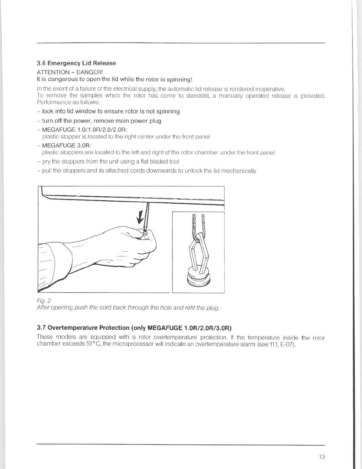
3.6 Emergency Lid Release
ATTENTION -DANGER!
It
is dangerous to open the lid while the rotor
is
spinning!
In the event ofa
fa
il
ure of the electrical supply,the automatic lid release is rendered inoperative.
To remove the samples when the rotor has
come
to standsti
ll,
a manually operated
re
lease is provided.
Perfo
rmance as
fo
llow
s:
-look into lid window to ensure rotor is not spinning
-turn off
the
power, remove main power plug
-MEGAFUGE 1.0/1.0R/2.0/2.0R:
plastic stopper is localed to the rightcenter underthe front panel
-MEGAFUGE 3.0R:
plastic stoppers are located to the left and right of the rotor chamber under the front panel
-pry the stoppers fr
om
the
un
it using a flat bladed tool
-pu
ll
t
he
stoppers and
it
s attached cords downwards to unlock
th
e lid
mec
ha
nical
ly
Fig.
2
After
openingpush the
co
rd
back
through the
ho
le
and
refit the plug.
3.7 Overtemperature Protection (only MEGAFUGE
1.0R/2.0R
/3
.0R)
These models are equipped with a rotor overtemperature protection.
If
th
e temperature inside the rotor
chamber exceeds
51
°C,
tt1e
microprocessor will indicate an overtemperature alarm (see
11.1,
E-07).
13
4. INSTALLATION
4.1 Location
The centrifuges are delivered in a special cardboard or wooden box.
Op
en the
box
carefull
y,
remove
th
e
transportprotec
ti
on
parts (foam) and put the
un
itm
its
location.
The unit must be set up on a sturdy,
le
vel laboratory t
ab
le
or
a suitable carriage with lockable wheels.
WARNING!
Do
not
place
the unitnext
to
a heat emitting element
or
instrument!
There must
be
a minimum clearance
to
the
wall
and
any
adjacent
equipment
of
10
cm
to
ensure
unrestricted
air
circulation.
The international european regulations for centrifuges require a safety zone
of
30
cm
around
the
centrifuge.
We
recommend
to
mark
this area
to
keep
away
persons
or
dangerous
goods
(e.g.
comprising
inflammable
or
infectious liquids}
during
centrifugation.
4.2 Electrical Requirements
Bef
or
e connecting
th
e Megafuge to the mains suppl
y,
make certain
th
at:
1.
the line voltage imprinted on
th
e identification plate is equal wi
th th
e one available (see 2.3 Mains Supply}
2.
th
e line voltage circuit breaker is a
13,
15 or
16
A
mp
type with a slow release feature commonly used for
instruments.
4.3 Main Power Switch
Connect the line cord plug
to
the
app
r
op
riate wall socket. Turn on the main power sw
it
ch located on the back
left hand side.
All
displaysand diodeswill light
up
tor two seconds (system check).
ATTENTION!
The main power switch should not be
us
ed (except in case of emergency)
to
interrupt the centrifuga
ti
on
.
Fo
r
t
hat,
the STOP key is provided.
Note: When powered
off,
all parameters of the last run a
re
main
ta
ined.
4.4
Opening
the
lid
The lid can only be opened with
tr1c
lid key when
the
yellow
LED
is li
t.
This is only possible when the rotor is
not turn
in
g and no er
ro
r messages
arc
displayed.
WARNING -DANGER!
The mechanical lid unlocking mechanism (see 3.6}
must
not
be
used
to
interrupt centrifugation.
It
is
absolutely
necessary
to
wait until the drive
has
come
to
standstill (can
be
checked
through the
window
in the
center
of
the lid).
14
5. ROTOR EXCHANGE
CAUTION!
Before inserting the rotor, make sure
that
the
rotor
chamber
is
free
of
contaminations (dust,
debris
etc.).
Condensate
or
residual sample
liquid
must
be
removed before centrifugation.
When clamping
on
the rotor
to
the drive shaft, the temperature
of
the rotor, the drive shaft
and
the collet
chuck
must all be in the range
of
10-30
°C
to
avoid loosening
of
the collet
chuck
by
temperature
imbalance.
WARNING!
The rotor
must
be
removed before transporting
the
centrifuge! Damage
to
the rotor and centrifuge may
result ifthe rotor
is
not
removed prior
to
transporting.
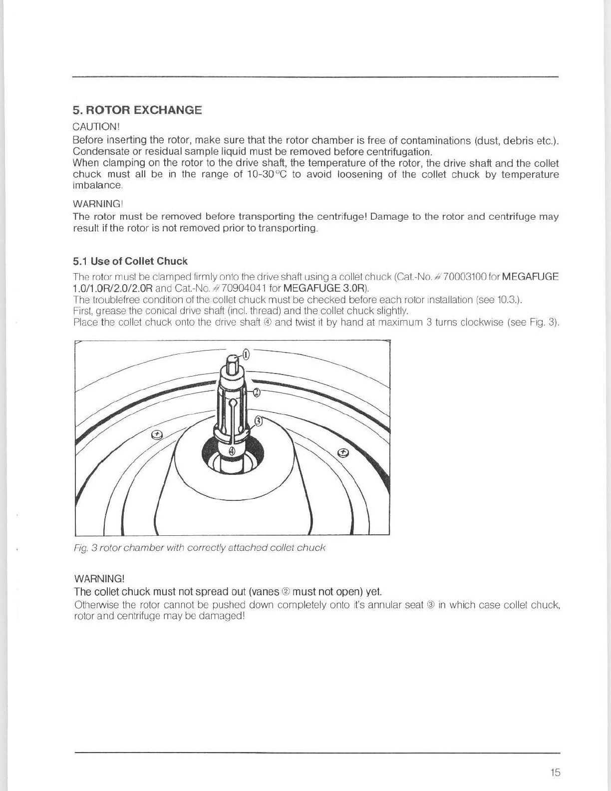
5.1
Use
of
Collet Chuck
The rotor mustbe clampedfirmlyontothe drive shaft using a collet chuck (Cat.-No.4"70003100for MEGAFUGE
1.0/1.0R/2.0/2.0R and Cat.-No.
//
70904041 for MEGAFUGE 3.0R).
The troublefree condition ofthe collet chuck must be checked before each rotor installation (see
10.3.).
Fi
rs
!,
grease
th
e conical drive shaft (incl.
th
read) and the collet chuck slightly.
Place the collet chuck onto the drive shaft
Ci>
and twist
it
by
hand at maxi
mum
3 turns clockwise (see
Fig.
3).
Fig.
3
rotor
cham
ber
with correctlyattachedcol/et
chuck
WARNING!
The collet
chuck
mustnotspread out (vanes ®
must
not
open) yet.
Otherwise the rotor cannot be pushed down completely onto it's annular seat @
in
which case
co
llet chuck,
rotor and centrifuge
may
be damaged!
15
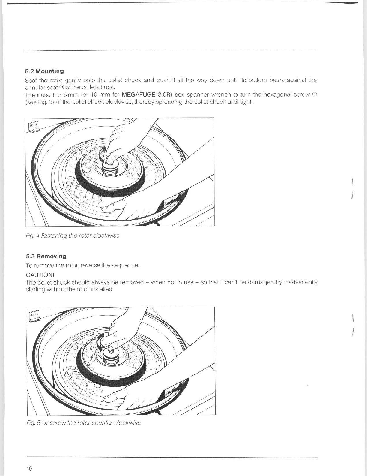
5.2 Mounting
Seat the rotor gently onto the collet
chuck
and push
it
a
ll
the
way
down un
til
i
ts
bottom bears against the
annular seat@ofthe collet chuck.
Then use the 6
mm
(or 10
mm
for
MEGAFUGE
3.0R)
box
spanner wrench to turn the hexagonal screw Ci)
(see Fig.
3)
of the
co
llet chuck clockwise,thereby spreading the collet chuck untiltight.
Fi
g.
4 Fastening the rotorclockwise
5.3
Removing
To remove the rotor, reverse the sequence.
CAUTION!
The collet ct1uck should always
be
removed -when not
in
use -so that it can't be damaged
by
inadve
rt
ently
starting without
the
rotor installed.
Fig.
5 Unscrewthe rotor counter-clockwise
16
}
6. ROTOR LOADING
WARNING!
The following instructions must
be
observed
exactly
to
avoid damage!
When using the sealed
rotor
#
3360
or
#
5315
,
the
loading instructi
ons
in
Sec
tion 6.7
must
be
obs
erved
in
every
det
ai
l.
All
adapters
must
only be loaded with t
ubes
whi
ch
have the right
shape
,
siz
e
and
material
(observe
tub
e manufacturer recommendations).
6.1
Swing-out
Rotors
WARNING!
In
swing
-
ou
t
rotors
all positions
mus
t be
occupied
with swinging
bucke
ts. The buckets
may
have an
ide
nt
i
fi
ca
ti
on letter which sta
te
s
H1e
weight class.
(e.
g. "E" or "D"). Only equal weight classes may be inserted
in opposi
ng
place
s.
Make
sure
that the
tubes
or
adapters
in
opposing
buckets
are identica
l.
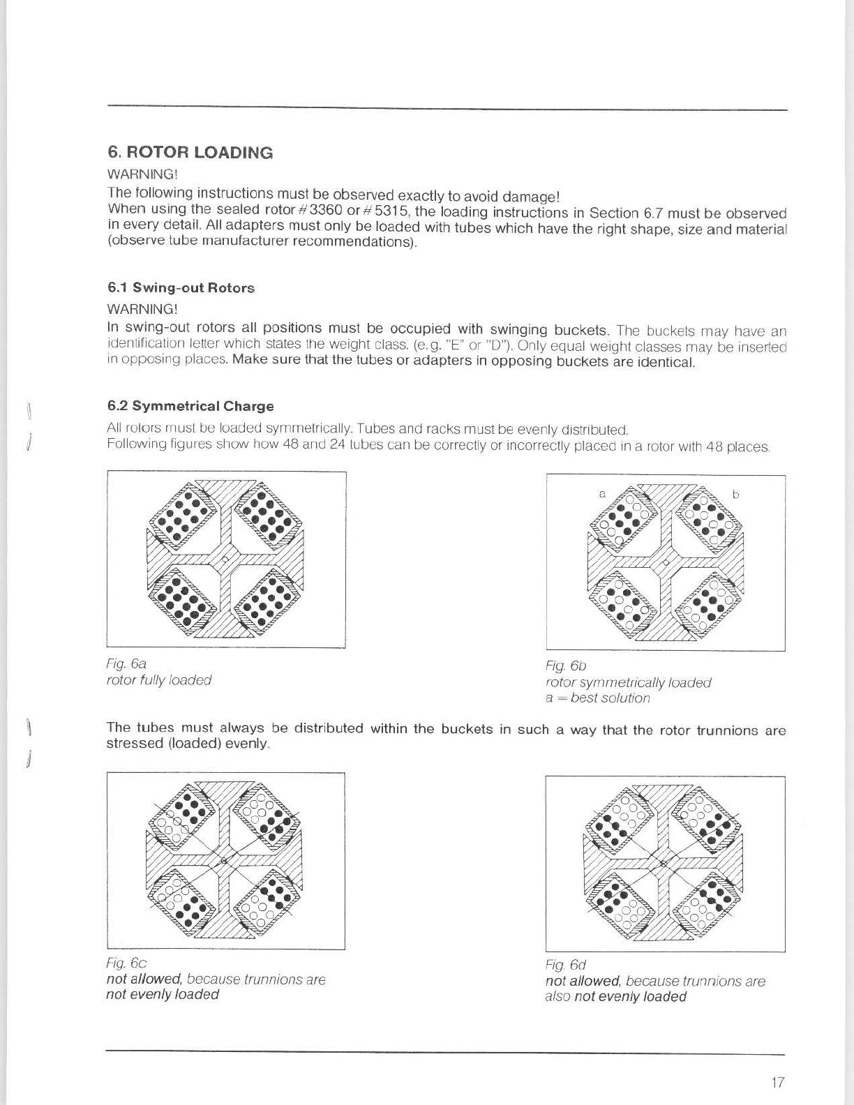
6.2
Symmetrical
Charge
All rotors must be loaded symme
tr
ically.Tubesand racks must be evenly distributed.
Following figures sh
ow
how 48 and 24 tubes can be correctly or in
co
rr
ectly placed in a rotor wi
th
48
places.
Fig.
6a
rotor fully loaded F
ig
.
6b
ro
tor
sy
mme
tr
ically loaded
a = be
st
solution
The
tubes
must
always be distributed within
the
buckets
in
such
a
way
that
the
roto
r
trnnnions
are
stressed
(loaded) evenly.
Fig.
6c
not
allowed
, because
tr
unni
ons
are
notevenly
loaded
Fig
.
6d
not
allowed
, because trunnions are
also
not
evenlyloaded
17
6.3
Distribution
of
Racks
In
order
to
avoid rotor wobble which might cause damage
to
both lhe centrifuge and the sample,
opposing
places
must
be
provided with identically loaded adapters, multiple carriers, tubes, bottles
etc
.
to
obtain
the
best
possible
balance.
Imbalance causes running
no
ises and produces a negative effect on
th
e
cJrive
system (excessive wear
out
of
the motorsupport).
The
permiss
i
ble
difference in total weight (or load) between
opposing
buckets
is
rotor
dependent
(see
RotorTables
2.4).
Todetermine the buc
ket
weights, any laboratory scale
is
suitable but a taring balance
is
best.
6.4 Tube Filling
Centrifuge tubes
up
to
approx. 30 mrn
in
diameter may
be
fil
led evenly
by
eye (up
to
5-10
mm
below the
rim,
depending upon size).
NOTE!
Using an angle
rot
or
and tubes without caps, only partial filling is possible (about
60%
and
75%
of the
maximum capacity). The actual amount of
fil
ling depends
on
the rotor's angle.
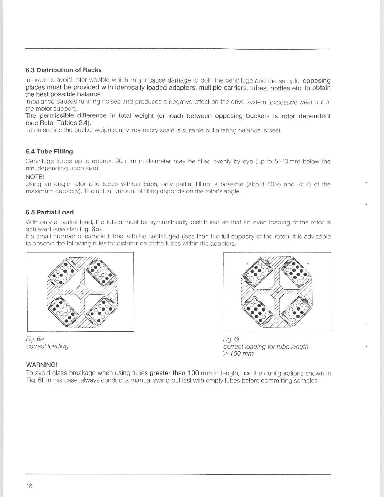
6.5
Partial
Load
Wi
th
only a partial load, the tubes must be symmetrically distributed so that an even loading of the rotor is
achieved (see also Fig. 6b).
If
a small number of sample tubes
is
to be centrifuged (less than the
ful
l capacity of the rotor), it is advisable
to
obseNe the following rules for distribution ofthe tubes within the adapters.
Fig.
6e
correct loading
WARNING!
Fig.
6f
correctloading for tube length
>
100mm
To
avoid
glass
brea
kage
wt1en
using
tubes
greater than 100 mm
in
l
ength,
use
the
configurations shown
in
Fig. 6f. In this case, always conducta manual swing-out test with emptytubes before committing samples.
18

6.6
Loading limits
rne material strength
of
every rotor
Is
limited with regmd to
1he
mass and speed-dependent forces actrng on its
yoke a
nd
other c
om
ponents du
ri
ng centrifuge operation.
HERAEUS rotors are designed
In
such a way that they still possess high strength reserves at the
maximum
perm1ss1ble
load and speed. Still
th
e maximum
permissible
limi
ts
must
not be
exc
ee
ded
.
It
is
the
operator's
responsibility
to
avoid overloa
ding
the rotor.
The max. permitted load
is
reached when all tubes are filled with a fluid of 1.2 g •
cm-
3 density. When the
density is higher th;rn
1.2
the tubes
may
only be partly filled. The total weight of a bucket
msy
not exceed the
value corresµonding
to to
tal fi
ll
ing with a liquid of 1.2
dens
i
ty.
As an alternative in such cases,
11
is possible
to
reduce the maximum perrrntted speed nm;:ix in accordance
with
the
following formula:
✓
To:ai
wc,y",I or
ltw
t•IIC:<ets
rul
s~m:il••
nadm =
nmax
w,tro
a ,i,,ns,1y
o:
1.2 9
cm
-
---
l
otdl
vvei<Jht
c:
tt1H
tJuckcts
11
c1
samp1t.?
w1
t
ll
h1ghnr c!e
ns1
N
6.7 Sealed Rotors
3360/5315
ATTENTION!
Sp
ecial
lo
ading instructions must be
observed
when
us
i
ng
the Seated Rotors#
3360
or
# 5315!
The operating instructions which are supplied with the sealed rotors must al
so
be read and observed exactly!
The Sealed Rotor is a swing-out rotor with a sealing lid designed for applications involving infectious
or
pathogenic samples. The centrifugal force of the buckets
,n
this rotor
Is
absorbed by an exterior ring of
fiberglass-reinforced pla
sti
c.
The lid reduces air friction whict1 a
ll
ows
th
is rotor to roach a high
er
max
i
mum
speed
th
an without lid.
Lock the rotor lid correctly to protect against spills due to broken glass or damaged tubes that may result
1n
aerosol cont
am
i
na
tion.
The buckets or
rotor"
3360
or
"'
5315 should be loaded wtlh Centn-Lab racks
or
inserts of identical exterior
dimensions and weight.
The rotor is intended to accomodato tubes 1
00
mm
in
length. However, shorter or longer tubes can be used.
Under certain circumstances, only the middle positions of the tube rack (sec
fig.
6Q
may
be occupied
by
the
longer tubes
to
prevent them from being knocked against the rotor yoke. Check
th
at
th
e buckets swing out
fr
eely.
Do not run the centrifuge with emptyglasstubes. Glass tubes
of
equal weight
may
exhibitverydifferent centers
ofgravity resulting in substan
ti
al
im
balance. This effect is reduced by filling
th
e tubes.
The unique
co
nstruction
of
the
Sealed Rotor requires special precautions when operating. The following
rules
must
be
absolutely
observed
in every detail.
WARNING!
It
is
esse
nt
ial thatthese rules are
prec
isely followed
in
order
to
preventdamage
to
the
rotor
or
ce
ntrifuge
resulting in a potential hazard
to
nearby
equipment
and
personnel.
1) Attach the rotor
co
rrectly
2) Ensure each counter-weightis
In
itsownposition 1-4 (only for rotor~ 3360being balanced
by
theseweights)
3) Insert
all
buckets and all tube rack
s.
All
buckets
must
be loaded.
4)
Load bucketsevenly and symmetrically
5)
Do not exceed permitted weight differences:
adjacent buckets: 100g
opposing buckets:
10
g
6) Do not exceed maximum sample load (
51
0g per bucket)
7) Check troublcfree operation
of
th
e rotor lid and observe expiration date (5 years laterthan imprinted date)
8) Lockrotor lid correctly
9) Do not exceed the speed limitof
th
e rotor (see RotorTables
2.4)
19
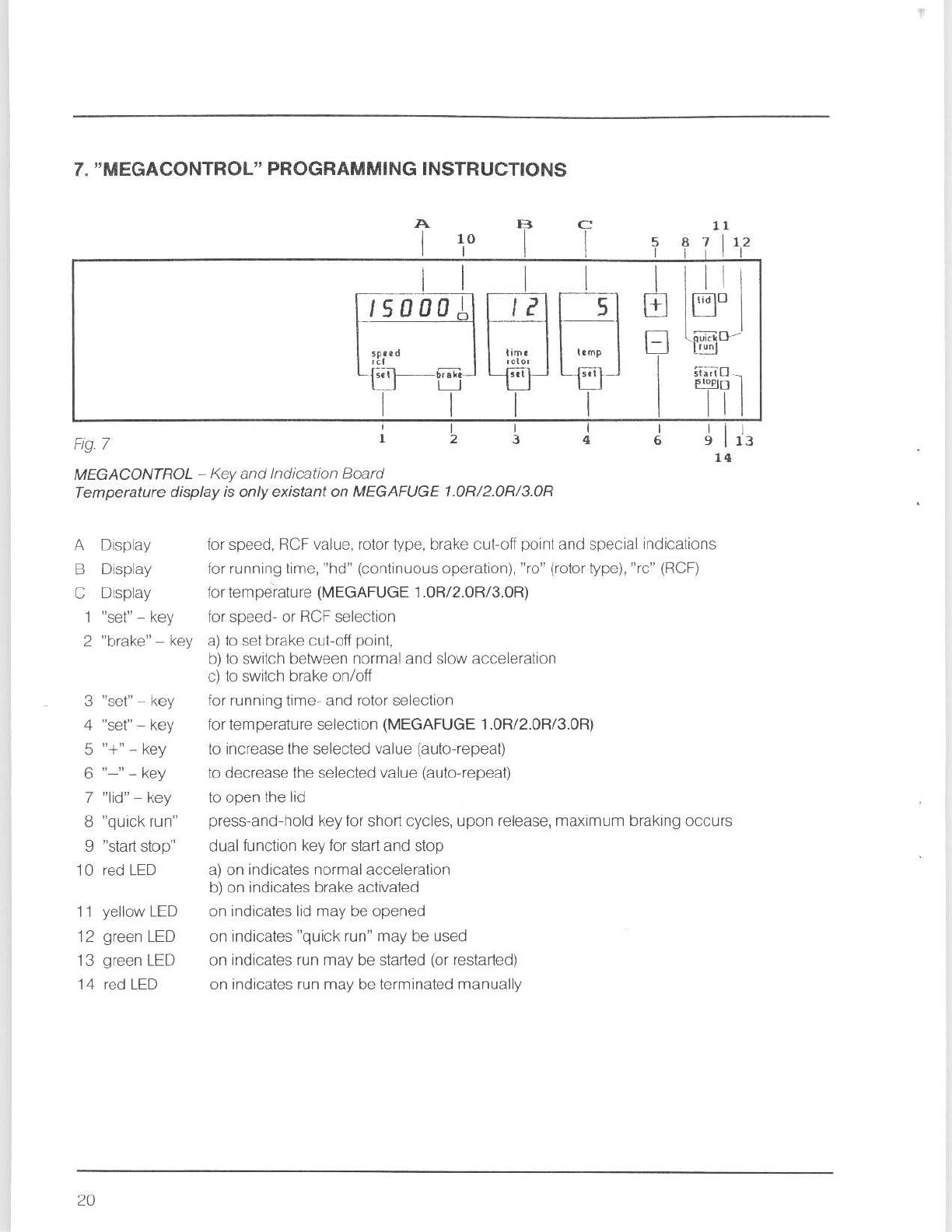
7. "MEGACONTROL" PROGRAMMING INSTRUCTIONS
A B C
11
I
10
I I 5 8 7 1
1i2
I I I
I I I I
~~:
/SOOD!
, 2 s
spud
ltm
p
,er
-e~b<al<r
-
starl·
□
-
1
--
L_J
~o
I I I I
I I I I I I .
Fig.
7 1 2 3 4 6 9 I1\
14
MEGACONTROL -
Key
and
Indication
Board
Temperature displayis onlyexistanton MEGAFUGE 1
.0R/2
.0R
/3.0R
A Display
B Display
C Display
1 "set" -key
2 "brake" -key
3 "set" -key
4 "set" -key
5 "+" -key
6 "-" -key
7 "lid" -key
8
"quick
run"
9 "start stop"
10
red
LED
11 yellow LED
12
green LED
13
green LED
14 red
LED
20
for speed, RCF value, rotor type, brake
cut
-offpoint
and
special indications
for running tirne,
"hd"
(conti
nuous
opera
ti
on), "ro" (rotor type), "re" (RCF)
for temperature (MEGAFUGE 1.0R/2.0R/3.0R)
for speed-
or
RCFselecti
on
a)
toset brakecut-off point,
b)
to switch between normal
and
sl
ow
acce
leration
c) to
sw
i
tch
brake on/off
for running
tim
e- and rotor selection
for
temperature sele
ct
ion (MEGAFUGE 1.0R/2.0R/3.0R)
to increase the selected value (auto-repeal)
to decrease the selected value (auto-repeat)
to
open
the lid
press-and-hold key for short
cyc
les,
upon
release,
maximum
braking
occ
u
rs
dual functi
on
key for start
and
stop
a)
on
indicates normal
acce
leration
b)
on
indicates brake activated
on
indicates lid
may
be
opened
on
indicates
"quick
run"
may
be used
on
indicates run
may
be
started (or restarted)
on
indicatesrun
may
be
terminated
manual
ly
This manual suits for next models
4
Table of contents
Other Heraeus Laboratory Equipment manuals


Popular Laboratory Equipment manuals by other brands


Belden
Belden HIRSCHMANN RPI-P1-4PoE installation manual

Koehler
Koehler K1223 Series Operation and instruction manual

Globe Scientific
Globe Scientific GCM-12 quick start guide

Getinge
Getinge 86 SERIES Technical manual

CORNING
CORNING Everon 6000 user manual

Biocomp
Biocomp GRADIENT MASTER 108 operating manual


