SNUG TOP UT PRO MT3 Service manual

Part #213779
UT PRO MT3
FORD RANGER
INSTALLATION INSTRUCTIONS
& OWNERS MANUAL
NOTICE D’INSTALLATION
ET GUIDE DU PROPRIÉTAIRE
INSTALACIÓN INSTRUCCIONES
& MANUAL DEL USUARIO

2
ENGLISH
TABLE OF CONTENTS
KEEP THESE INSTALLATION INSTRUCTIONS FOR FUTURE REFERENCE
Snugtop UT PRO MT3 Cap Components ...................................................................................................... 3
Cap Installation Instructions................................................................................................................................ 4
Installing Gap Filler................................................................................................................................................ 5
Front Seal Placement Procedure....................................................................................................................... 6
Positioning The Leveler Strips ............................................................................................................................ 6
Placing The Cap On The Truck........................................................................................................................... 7
Secure Cap To Truck............................................................................................................................................. 8
Coding Your Door Locks...................................................................................................................................... 8
Making Electrical Connections....................................................................................................................8 – 9
Final Inspection.....................................................................................................................................................10
Removing Your Truck Cap..................................................................................................................................10
Toolbox Assembly – Passenger Side....................................................................................................10 – 12
Toolbox Assembly – Driver Side.............................................................................................................13 – 14
Service Parts UT PRO MT3..............................................................................................................................15
Limited Warranty..................................................................................................................................................16
Caring For Your Truck Cap ................................................................................................................................17
3
ENGLISH
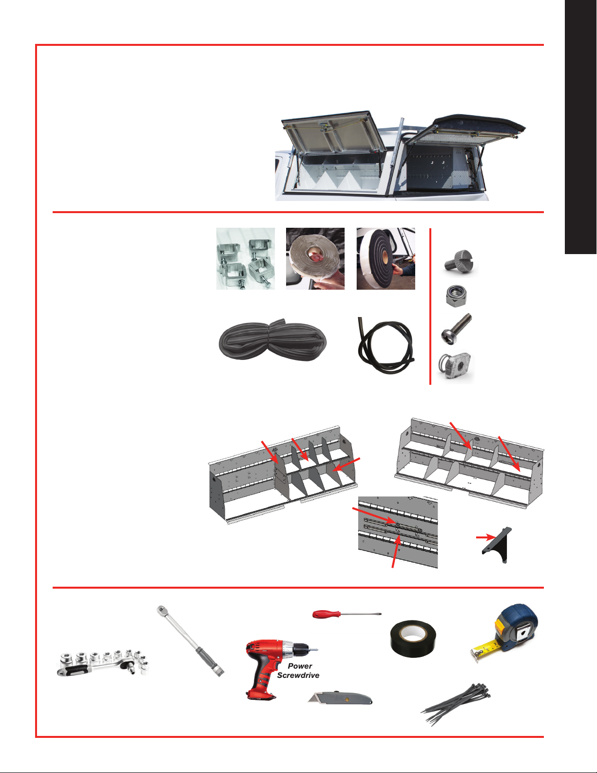
Center
Support
Half
Shelf
Lower
Divider
Center
Divider
CHECKLIST
q (4) Clamps and Bolts
q Putty/Butyl Tape
q Wiring Harness (Not shown)
q 6’ Front Bulkhead D-Seal
q 30’ Foam Seal
q (1) Leveler Strip
SHELVING COMPONENTS
q (1) Full Shelf
q (1) Half Shelf
q (6) Upper Dividers
q (6) Lower Dividers
q (4) Hardware Kits
q (1) Center Support
q (1) Center Divider
q (3) Locking Brackets
q (6) Shelf Supports
SNUGTOP UT PRO MT3 CAP COMPONENTS
UNPACK COMPONENTS AND INSPECT FOR MISSING OR DAMAGED ITEMS
6” Nylon
Cable Ties
Torque
Wrench 12 Ft. Tape
Measure
PLEASE SELECT ONE
q 5’ SNUGTOP UT PRO MT3 CAP
q 6’ SNUGTOP UT PRO MT3 CAP
TOOLS NEEDED
Wrenches,
9/16” Socket
1/2” Socket,
7/16” Combo Wrench
HARDWARE KITS
• 1/4 - 20 x .75
Slotted Thumb
Screw (12)
• 1/4 - 20
E-Stop Nut
Zinc Plated (48)
• 1/4 - 20
Phillips
Screw (48)
Clamps and
Bolts Putty/Butyl
Tape Foam Seal
• 1/4 -
Channel
Nuts (12)
6’ Front Bulkhead D-Seal
Leveler Strip
Electrical
Tape
Power
Screwdriver
Utility Knife
SHELVING COMPONENTS
Full Shelf
Upper Divider
Screwdriver
Locking
Bracket
Shelf
Support

4
ENGLISH
INSTALLATION INSTRUCTIONS
OPEN THE TRUCK TAILGATE AND CLEAN TRUCK BED RAILS
BEFORE YOU INSTALL
• We recommend using safety glasses
during installation.
• Keep truck tailgate down at all times
during assembly.
• Cap installation or removal requires four
people or use of a forklift.
• Read all instructions thoroughly before
installing cap.
INSTALLING CAP
(FOUR PEOPLE OR
FORKLIFT REQUIRED)
1. Clean bedrails, top of bulkhead, rear
truck window and front window of cap
with 50/50 isopropyl alcohol and a
clean cloth.
2. Starting at the drivers side rear of the
cap, apply the foam seal 5/8” from
the outside cap edge in a straight line
toward the front.
3. Repeat on the passengers side from
rear to front.
4. Apply the foam seal to the front
underside of the cap, flush against both
the drivers and passengers side foam
seal.
Starting at the driver side rear, apply the foam seal
5/8” from the outside cap edge in a straight line toward
the front.
Repeat on the passenger side from rear to front.
Apply the foam seal to the front underside of the cap,
butting up to both the driver and passenger side
foam seal.
Scan to See
Installation
Videos
5
ENGLISH
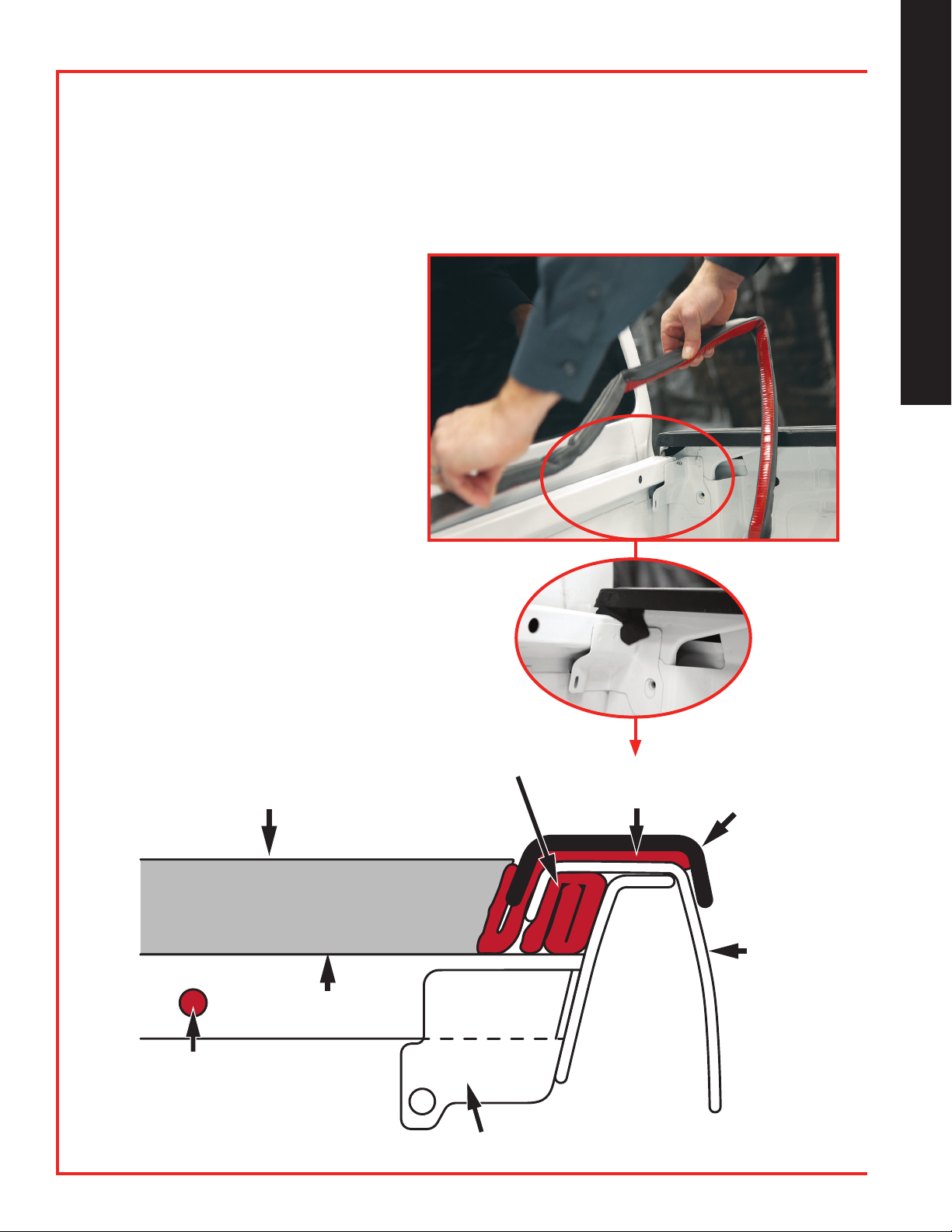
INSTALLING GAP FILLER
THIS FORD RANGER TRUCK BED HAS A GAP BETWEEN THE SIDE PLASTIC BED RAIL
CAPS AND THE FRONT BULKHEAD. THE FOLLOWING STEPS SHOULD BE
REPEATED ON BOTH THE DRIVER AND PASSENGER SIDES
1. Locate gaps in the bed.
2. Cut a 6” piece of putty/butyl
tape. Fold putty/butyl tape into
thirds and compact into gap
area, creating a transition from
the bedrail to the top of the
front bulkhead.
3. Repeat on the other side.
4. Cut a 1” piece of putty/
butyl tape and fill in holes in
bulkhead, both driver and
passenger sides.
5. Cut a 2” piece of putty/butyl
tape, lift bedrail cap and fill
in gap with putty/butyl tape
between bedrail cap and
front of bulkhead. Leave
extra putty/butyl tape on
top of the bulkhead.
MATERIALS REQUIRED
“D”-SEAL
2" PUTTY/
BUTYL TAPE
BED
CAP
TRUCK
FENDER
6" PUTTY/
BUTYL
TAPE
BED CORNER SUPPORT
1" PUTTY/BUTYL
TAPE
TOP OF BULKHEAD
Apply putty/
butyl tape
(color of putty
may vary)
Table of contents
Languages:
Other SNUG TOP Automobile Accessories manuals

Popular Automobile Accessories manuals by other brands


ULTIMATE SPEED
ULTIMATE SPEED 279746 Assembly and Safety Advice

SSV Works
SSV Works DF-F65 manual

ULTIMATE SPEED
ULTIMATE SPEED CARBON Assembly and Safety Advice

Witter
Witter F174 Fitting instructions

WeatherTech
WeatherTech No-Drill installation instructions

TAUBENREUTHER
TAUBENREUTHER 1-336050 Installation instruction