SoarTronic IOIO UART User manual

1
Soartronic IOIO UART interface v2e
assembly manual
www.soartronic.com

2
This manual is for both
IOIO v1 and IOIO-OTG
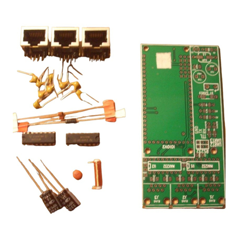
Components assembled should look like this:
components marked with RED arrows have polarity, and
must be soldered as shown in the picture.
Also make sure that the holes of micro-ships marked with
YELLOW arrows are as shown on the picture.
The BLUE arrows show places for extra components, which may be used
to filter the 5V output from IOIO-OTG card. We have not tested this, and
it is likely that placing coil and capacitor do not really help –but if you
test (and I souppose you know what you are doing..) please tell us what
was the result…

3
IF you have the first generation IOIO card
which looks like this:
You should connect the points marked with white circles
on back side of the Soartronic IOIO UART interface board.
One circle is marked with RED arrow for an example.
We also recommend to connect the corners for IOIO card
stability (corners marked with YELLOW arrow)
You MUST also connect jumper wire between these two
connection holes marked with WHITE arrow.

4
IF you have the second generation card, IOIO-OTG card
which looks like this:
You should connect the points marked with white circles
on top side of the Soartronic IOIO UART interface board.
One circle is marked with RED arrow for an example.
We also recommend to connect the corners for IOIO card
stability (one corners marked with YELLOW arrow)
You MUST also connect jumper wires (both marked with
short RED lines) between these connection holes marked
with WHITE arrow.

5
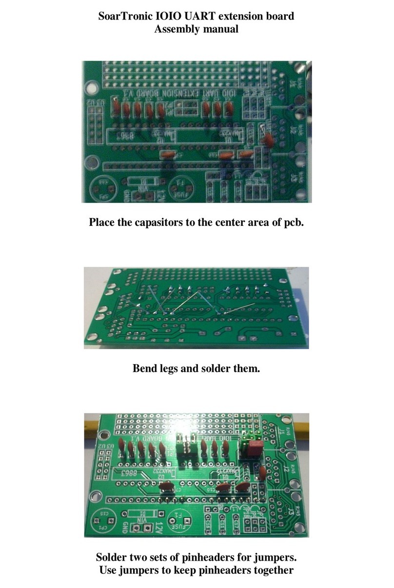
In earlier shown example pictures surface mounted
capacitors were used. If you have trough hole
components, your board will look more like this:
And this:
Note also on the above picture the orientation of the
larger capacitors, they have polarity. The small ones do
not. The coil in this picture may have been replaced with
ferrite, as shown in the earlier pictures.

6
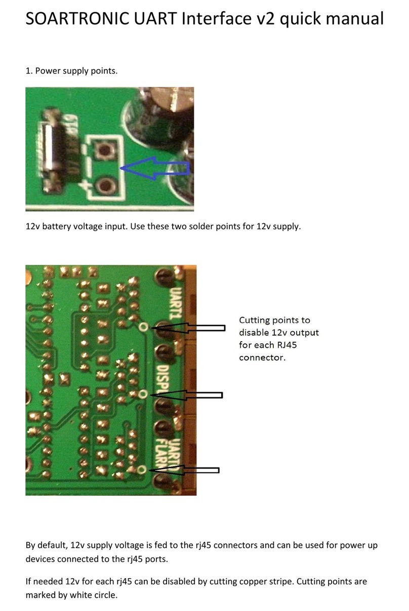
ON the backside of the Soartronic UART Interface V2e
there are 3 connection points to connect 12V or 5 V lines
to the RJ45 connectors. These jumpers are marked with
YELLOW arrows in this picture:
JP1 connects 12V to the Flarm and Display RJ45
connectors according to IGC standard. If JP1 is not
connected, 12V line is NOT connected.
JP2 connects 12V to the UART RJ45 connectors according
to IGC standard. If JP1 is not connected, 12V line is NOT
connected.
JP3 connects UART_1 RJ45 connector pin6 with the 5V
line of the Soartronic IOIO UART Interface and the IOIO
card. This can be used to power the IOIO card, or to feed
5V out of the card. If powered from outside with 5V THE
12V LINE MUST NOT BE CONNECTED!

7
About the use of JP1:
If you have FLARM that has already 12V supply, and you
want to keep that instead of feeding 12V from Soartronic
IOIO interface, do not connect JP1. If your FLARM has
separate 12V/GND wires connected, you just connect the
Flarm port to the FLARM dataport with straight RJ cable.
RS232 data communication is now connected.
If you have a RJ cable feeding power to your FLARM,
disconnect that RJ cable from FLARM and connect it to
the UART 0 / Flarm RJ45 port, and then and add a new
straight RJ cable between Soartronic IOIO interface Flarm
connector and FLARM. Now RS232 data communication is
connected, and 12V from outside source is relayed
trought the RJ45 splitter to your FLARM device.
If you solder connection over JP1 the UART 0 Flarm and
Display RJ45 connectors will feed 12V to your cable
according to IGC standard. With one cable you can feed
power to your FLARM and read/write RS232 data.

8
About the use of JP2
JP2 connects 12V to the UART 1 RJ45 connector.
JP2 is use to connect 12V to the RJ45 connector according
to IGC standard. This way you can connect RS232
communication and 12V power to devices like
Volkslogger, and some Colibri loggers.
Before connecting any logger or other device, please
make sure that your device uses IGC standard RJ
connector, and that your RJ cable is straight.
Straight (Trough) RJ cable vs. other possible connections:

9
About the use of JP3
Do not solder JP3 if you do not know what you are doing.
JP3 connects 5V of the IOIO card to the pin 6 of the UART
1 RJ45 connector.
If 12V is supplied to the IOIO card, this 5V is generated by
the IOIO card, and then fed out via pin 6.
If 5 V is generated by the device that is connected to this
pin 6, it can be used by the IOIO card instead of its own
5V regulated from the 12V supply voltage. In that case
12V should NOT be connected to the Soartronic IOIO
UART interface!

10
Diode direction print is missing from many UART
interface boards, since it was placed too close to copper.
The white arrows in his picture shows how to solder the
diodes:
(the holes next to the two diodes is for fixing wires
connected to UART2 and UART3 using narrow wire
straps.)

11
Place pin-headers for the first generation IOIO card as
shown in images below.
THIS IS IMPORTANT!!! For first generation IOIO make sure the voltage and GND
connection pins are exactly as shown here, and as marked with white circles
One pin that is used to connect voltage measurement to
12V line is missing from these pictures! Place for that pin is
marked with RED arrow, and it is marked with white circle.
You should have IOIO kard like this…

12
Place pin-headers for IOIO-OTG card as shown in images
below.
THIS IS IMPORTANT!!! For IOIO OTG make sure the voltage and GND connection
pins are exactly as shown here, and as marked with white circles
The pin that is used to connect voltage measurement to
12V line is missing from these pictures! Place for that pin
is marked with RED arrow, and it is marked with white
circle on the circuit-board.
You should have IOIO-OTG card like this…
Finally solder the IOIO card.

13
The USB connector should point into the opposite
direction with the RJ45 connectors, and all the
components and the USB connector should be on
the TOP.
Just for an example:
This picture shows jumpers for
-Connecting 12V line to FLARM RJ45 cables
-Connecting jumpers for use with IOIO-OTG
>> In this example FLARM is powered from Soartronic
interface card, and IOIO-OTG is used. >>

14
IOIO UART interface connections:
A) UART 0, FLARM splitter. These two RJ45 IGC standard ports are connected together as a
“RJ45 splitter”. Port market “FLARM” can communicate with FLARM. “DISPLAY” port can
be used to forward FLARM communication to other devices like display units,
variometers, etc. Please note that this splitter is intelligent. This means, that you can
have two devices communication with FLARM without need of a “declare/fly” switch, as
long as they do not write to FLARM simultaneously!
B) UART 1, another IGC standard RJ45 connector. This can connect with loggers and
variometers with IGC standard RJ45 or RJ12 ports.
C) UART 2, Connection points for RS232 level serial communication (RX/TX/GND). Solder
here connection wires to SUBD9 connectors or other special connectors. Use the holes in
PCB for fixing the wires using narrow wire straps.
D) UART 3, Connection points for TTL level serial communication (RX/TX/GND). You can
connect here TTL level serial communication devices like Bluetooth chips, come loggers,
etc. You can also use an external TTL/RS232 converter if you need to use all 4 UARTs.
A
B
C
D
Other manuals for IOIO UART
2
Other SoarTronic Recording Equipment manuals
