Woodward SPM-D2-10/YB User manual

37617B
Manual
From Release 7.10-0
Manual 37617B
SPM-D2-10/YB
Synchronizing Unit

Manual 37617B SPM-D2-10/YB - Synchronizing Unit
Page 2/51 © Woodward
WARNING
Read this entire manual and all other publications pertaining to the work to be performed before in-
stalling, operating, or servicing this equipment. Practice all plant and safety instructions and precau-
tions. Failure to follow instructions can cause personal injury and/or property damage.
The engine, turbine, or other type of prime mover should be equipped with an overspeed (overtemper-
ature, or overpressure, where applicable) shutdown device(s), that operates totally independently of
the prime mover control device(s) to protect against runaway or damage to the engine, turbine, or oth-
er type of prime mover with possible personal injury or loss of life should the mechanical-hydraulic
governor(s) or electric control(s), the actuator(s), fuel control(s), the driving mechanism(s), the link-
age(s), or the controlled device(s) fail.
Any unauthorized modifications to or use of this equipment outside its specified mechanical, electri-
cal, or other operating limits may cause personal injury and/or property damage, including damage to
the equipment. Any such unauthorized modifications: (i) constitute "misuse" and/or "negligence" with-
in the meaning of the product warranty thereby excluding warranty coverage for any resulting damage,
and (ii) invalidate product certifications or listings.
CAUTION
To prevent damage to a control system that uses an alternator or battery-charging device, make sure
the charging device is turned off before disconnecting the battery from the system.
Electronic controls contain static-sensitive parts. Observe the following precautions to prevent dam-
age to these parts.
Discharge body static before handling the control (with power to the control turned off, contact a
grounded surface and maintain contact while handling the control).
Avoid all plastic, vinyl, and Styrofoam (except antistatic versions) around printed circuit boards.
Do not touch the components or conductors on a printed circuit board with your hands or with
conductive devices.
OUT-OF-DATE PUBLICATION
This publication may have been revised or updated since this copy was produced. To verify that you
have the latest revision, be sure to check the Woodward website. The latest version of most publica-
tions is available at:
http://www.woodward.com/publications
If your publication is not there, please contact your customer service representative to get the latest
copy.
Important definitions
WARNING
Indicates a potentially hazardous situation that, if not avoided, could result in death or serious injury.
CAUTION
Indicates a potentially hazardous situation that, if not avoided, could result in damage to equipment.
NOTE
Provides other helpful information that does not fall under the warning or caution categories.
Woodward reserves the right to update any portion of this publication at any time. Information provided by Woodward is believed to be
correct and reliable. However, Woodward assumes no responsibility unless otherwise expressly undertaken.
© Woodward
All Rights Reserved.

Manual 37617B SPM-D2-10/YB - Synchronizing Unit
© Woodward Page 3/51
Copyright And Disclaimer
Disclaimer
All information and instructions in this manual have been provided under due consideration of applicable guide-
lines and regulations, the current and known state of the art, as well as our many years of in-house experience.
Woodward GmbH assumes no liability for damages due to:
•Failure to comply with the instructions in this manual
•Improper use / misuse
•Willful operation by non-authorized persons
•Unauthorized conversions or non-approved technical modifications
•Use of non-approved spare parts
The originator is solely liable to the full extent for damages caused by such conduct. The agreed upon obligations
in the delivery contract, the general terms and conditions, the manufacturer’s delivery con-ditions, and the statuto-
ry regulations valid at the time the contract was concluded, apply.
Copyright
This manual is protected by copyright. No part of this manual may be reproduced in any form or incor-porated into
any information retrieval system without written permission of Woodward GmbH.
Delivery of this manual to third parties, duplication in any form - including excerpts - as well as exploita-tion and/or
communication of the content, are not permitted without a written declaration of release by Woodward GmbH.
Service And Warranty
Our Customer Service is available for technical information. Please see last page for the contact data.
Warranty terms
Please enquire about the terms of warranty from your nearest Woodward representative.
For our contact search webpage please go to: http://www.woodward.com/Directory.aspx
Intended Use
The SPMD device must be used exclusively for synchronization of two electrical systems. By opening the device
you will loose any warranty.
Any unauthorized modifications to or use of this equipment outside its specified mechanical, electrical, or other
operating limits may cause personal injury and/or property damage, including damage to the equipment. Any
such unauthorized modifications: (1) constitute "misuse" and/or "negligence" within the meaning of the product
warranty thereby excluding warranty coverage for any resulting damage, and (2) invalidate product certifications
or listings.
Before starting any operation and after any modification of the parameterization make a documentary proof that
your programming and parameterization meets the requirements of your synchronization concept.
Typical applications for this product family/device line are for instance:
Synchronizing a mains parallel Generator to the mains
Any usage beyond these applications the devices are not designed for. This applies also to the use as a partly
completed machinery. The manufacturer cannot be held liable for any resulting damage, the user alone bears the
risk for this. As to the appropriate use of the device: The technical data and tolerances specified by Woodward
have to be met.

Manual 37617B SPM-D2-10/YB - Synchronizing Unit
Page 4/51 © Woodward
Revision History
Rev.
Date
Editor
Changes
B
2016-02-17
GG
UL rating added to technical data / ambient variables for N & XN packages. See page 51.
A
2016-01-27
GG
Changed product name “SPM-D-xxx” to “SPM-D2-xxx”
NEW
2015-12-09
GG
Release
Contents
Copyright And Disclaimer ......................................................................................................................... 3
Service And Warranty............................................................................................................................... 3
Intended Use............................................................................................................................................. 3
CHAPTER 2. GENERAL INFORMATION.........................................................................................7
CHAPTER 3. ELECTROSTATIC DISCHARGE AWARENESS .............................................................8
CHAPTER 4. INSTALLATION .......................................................................................................9
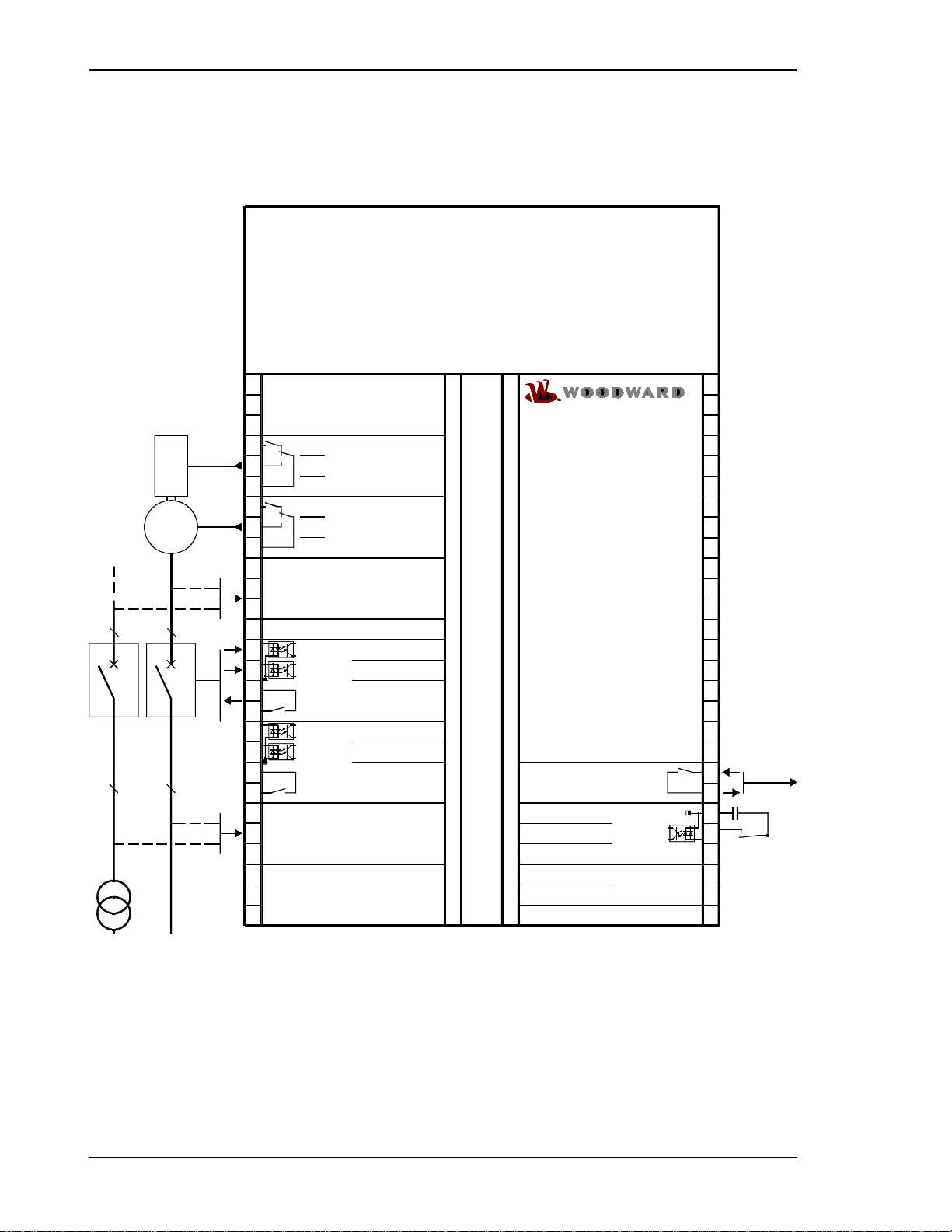
Wiring Diagram....................................................................................................................................... 10
SPM-D2-10/YB (24 Vdc) .............................................................................................................. 10
SPM-D2-10/NYB (90..250 Vac or 120…375 Vdc)........................................................................ 11
Reference Point...................................................................................................................................... 12
Power Supply.......................................................................................................................................... 12
Measuring Inputs .................................................................................................................................... 13
Mains/System U1 ......................................................................................................................... 13
Generator/System U2................................................................................................................... 13
Discrete Inputs........................................................................................................................................ 14
Relay Outputs......................................................................................................................................... 15
Controller Outputs................................................................................................................................... 15
CHAPTER 5. DESCRIPTION OF FUNCTIONS ...............................................................................16
Functionality............................................................................................................................................ 16
Table of Functions........................................................................................................................ 16
Control Inputs.......................................................................................................................................... 17
Isolation of the Power Supply from the Discrete Inputs.......................................................................... 17
Operating Conditions.............................................................................................................................. 18
No Load Control ........................................................................................................................... 18
Synchronizing............................................................................................................................... 18
Dead Bus Start (Asynchronous Add-On)...................................................................................... 19
Synch-Check ................................................................................................................................ 19
Control Outputs....................................................................................................................................... 20
CHAPTER 6. DISPLAY AND OPERATING ELEMENTS ...................................................................21
Brief Explanation of the LEDs and Push Buttons ................................................................................... 22
LEDs............................................................................................................................................. 22
Buttons ......................................................................................................................................... 22
Others........................................................................................................................................... 22
LEDs....................................................................................................................................................... 23
Push Buttons........................................................................................................................................... 25
LC Display............................................................................................................................................... 26

Manual 37617B SPM-D2-10/YB - Synchronizing Unit
© Woodward Page 5/51
Display Monitoring in Automatic Mode: Double Voltage/Frequency Display.................................26
Display Monitoring in Automatic Mode: Alarm Indication..............................................................26
CHAPTER 7. CONFIGURATION..................................................................................................27
Configure Basic Data ..............................................................................................................................28
Configure Basic Settings.........................................................................................................................30
Voltage Measuring........................................................................................................................30
Configure Controller................................................................................................................................32
No Load Control............................................................................................................................32
Frequency Controller.....................................................................................................................33
Voltage Controller .........................................................................................................................34
Synchronization.......................................................................................................................................35
Configure Synchronization............................................................................................................35
Dead Bus Start..............................................................................................................................36
Relay Output 16-17.......................................................................................................................37
Synchronizing Time Monitoring.....................................................................................................38
CHAPTER 8. COMMISSIONING..................................................................................................39
APPENDIX A. DIMENSIONS ......................................................................................................41
APPENDIX B. TECHNICAL DATA...............................................................................................42
APPENDIX C. LIST OF PARAMETERS ........................................................................................44
APPENDIX D. SERVICE OPTIONS..............................................................................................46
Product Service Options..........................................................................................................................46
Returning Equipment For Repair.............................................................................................................46
Packing A Control .........................................................................................................................47
Return Authorization Number RAN...............................................................................................47
Replacement Parts..................................................................................................................................47
How To Contact Woodward....................................................................................................................48
Engineering Services ..............................................................................................................................49
Technical Assistance ..............................................................................................................................50

Manual 37617B SPM-D2-10/YB - Synchronizing Unit
Page 6/51 © Woodward
Illustrations and Tables
Illustrations
Figure 4-1: Wiring diagram SPM-D2-10/YB ............................................................................................................................ 10
Figure 4-2: Wiring diagram SPM-D2-10/NYB ......................................................................................................................... 11
Figure 4-3: Reference point....................................................................................................................................................... 12
Figure 4-4: Power supply........................................................................................................................................................... 12
Figure 4-5: Measuring inputs - mains - system U1.................................................................................................................... 13
Figure 4-6: Measuring inputs - generator - system U2............................................................................................................... 13
Figure 4-7: Discrete inputs - control inputs - power circuit breaker.......................................................................................... 14
Figure 4-8: Discrete inputs - control inputs - operation............................................................................................................. 14
Figure 4-9: Relay outputs - control output #1 (CB operation)................................................................................................... 15
Figure 4-10: Relay outputs - control output #2.......................................................................................................................... 15
Figure 4-11: Controller - three-position controller .................................................................................................................... 15
Figure 6-1: Front foil................................................................................................................................................................. 21
Figure 8-1: Dimensions ............................................................................................................................................................. 41
Tables
Table 4-1: Conversion chart - wire size....................................................................................................................................... 9
Table 5-1: Operating modes....................................................................................................................................................... 16
Table 5-2: Operating modes - operating conditions................................................................................................................... 16

Manual 37617B SPM-D2-10/YB - Synchronizing Unit
© Woodward Page 7/51
Chapter 2.
General Information
The SPM-D2-10/YB is a three-phase synchronizing unit with expanded dead bus start functionality. The follow-
ing functions can be realized by using the appropriate discrete inputs:
Synchronization
Synch-check
Dead bus start
The SPM-D2 starts as a standard unit that may have additional functions added with each package. The model of
the SPM-D2 is designated as follows:
SPM-D2-10
4
0
B/
YB
Packages according to the Package list.
These packages can be found in the manual. Each headline points out
if the described function is standard or part of a package.
Mounting
[B].. Flush-mounting
CT's, current transformers, secondary
[0] = no CT
Voltage transformers/PT's, secondary
[1] = 100 Vac
[4] = 400 Vac
Type
Examples:
SPM-D2-1040B/YB (standard unit with 400 Vac PT measuring inputs, no CT inputs,
flush mounted, 24 Vdc power supply)
SPM-D2-1010B/NYB (standard unit with 100 Vac PT measuring inputs, no CT inputs,
flush mounted, 90 to 250 Vac / 120 to 375 Vdc power supply)
Intended Use The unit must only be operated as described in this manual. The prerequisite for a proper and safe
operation of the product is correct transportation, storage, and installation as well as careful operation and
maintenance.
NOTE
This manual has been developed for a unit equipped with all available options. Inputs/outputs,
functions, configuration screens and other details described, which do not exist on your unit,
may be ignored.
The present manual has been prepared to enable the installation and commissioning of the unit.
Because of the large variety of parameter settings, it is not possible to cover every possible
combination. The manual is therefore only a guide. In case of incorrect entries or a total loss of
functions, the default settings can be taken from the enclosed list of parameters at the rear of
this manual.

Manual 37617B SPM-D2-10/YB - Synchronizing Unit
Page 8/51 © Woodward
Chapter 3.
Electrostatic Discharge Awareness
All electronic equipment is static-sensitive, some components more than others. To protect these components
from static damage, you must take special precautions to minimize or eliminate electrostatic discharges.
Follow these precautions when working with or near the control.
1. Before doing maintenance on the electronic control, discharge the static electricity on your body to ground
by touching and holding a grounded metal object (pipes, cabinets, equipment, etc.).
2. Avoid the build-up of static electricity on your body by not wearing clothing made of synthetic materials.
Wear cotton or cotton-blend materials as much as possible because these do not store static electric charg-
es as much as synthetics.
3. Keep plastic, vinyl, and Styrofoam materials (such as plastic or Styrofoam cups, cup holders, cigarette
packages, cellophane wrappers, vinyl books or folders, plastic bottles, and plastic ash trays) away from the
control, the modules, and the work area as much as possible.
4. Opening the Control unit will void the warranty!
Do not remove the printed circuit board (PCB) from the control cabinet unless necessary. If you must re-
move the PCB from the control cabinet, follow these precautions:
Make sure that the unit is completely de-energized (all connectors have to be disconnected).
Do not touch any part of the PCB except the edges.
Do not touch the electrical conductors, connectors, or components with conductive devices or with bare
hands.
When replacing a PCB, keep the new PCB in the plastic antistatic protective bag it comes in until you
are ready to install it. Immediately after removing the old PCB from the control unit, place it in the an-
tistatic protective bag.
WARNING
To prevent damage to electronic components caused by improper handling, read and observe the pre-
cautions in Woodward manual 82715, Guide for Handling and Protection of Electronic Controls, Printed
Circuit Boards, and Modules.

Manual 37617B SPM-D2-10/YB - Synchronizing Unit
© Woodward Page 9/51
Chapter 4.
Installation
CAUTION
A circuit breaker must be provided near to the unit and in a position easily accessible to the operator.
This must also bear a sign identifying it as an isolating switch for the unit.
NOTE
Connected inductive devices (such as operating current coils, undervoltage tripping units, or auxiliary
or power contacts) must be connected to a suitable interference suppressor.
WARNING
All technical data and ratings indicated in this chapter are not definite! Only the values indicated in Ap-
pendix B: Technical Data on page 42 are valid!
The following chart may be used to convert square millimeters [mm²] to AWG and vice versa:
AWG
mm²
AWG
mm²
AWG
mm²
AWG
mm²
AWG
mm²
AWG
mm²
30
0.05
21
0.38
14
2.5
4
25
3/0
95
600MCM
300
28
0.08
20
0.5
12
4
2
35
4/0
120
750MCM
400
26
0.14
18
0.75
10
6
1
50
300MCM
150
1000MCM
500
24
0.25
17
1.0
8
10
1/0
55
350MCM
185
22
0.34
16
1.5
6
16
2/0
70
500MCM
240
Table 4-1: Conversion chart - wire size

Manual 37617B SPM-D2-10/YB - Synchronizing Unit
Page 10/51 © Woodward
Wiring Diagram
≡≡≡≡≡≡≡≡≡≡≡≡≡≡≡≡≡≡≡≡≡≡≡≡≡
SPM-D2-10/YB (24 Vdc)
Referencepoint
Command:closeCB
alternatively
Subjectto technicalmodifications.
Voltage - SystemU1
CB
CB
alternatively
Drive
Reply:CBisopen
EnableCB
Voltage - SystemU2
Common (term. 3, 4,5,6,53,54)
Configuration locked
12
Readinessforoperation Function:
make-
contact
0Vdc
24 Vdc
The socket for the PC configuration
is situated on the side of the unit.
SPEED
Three-position controller
VOLTAGE
Three-position controller
lower
raise
raise
lower
Battery
SPM-D2-10/YB (Synchronizing Unit)
Message: Connect2
Synch-check
Enableblack start
*At theterminal 21/51"Voltage L2/ N"
the following as tobeapplied:
- voltage measuring"1 phase L-N" = zero-conductor N
- voltage measuring"1 phaseL-L" =conductor L2
- voltage measuring"3 phase" = conductor L2
Forvoltage measuring "1phase L-N" and
"1phase L-L"you haveto short-circuit the
terminals 21/22 as well as terminals 51/52.
14
05 15
3
3
L1
L2 /N*
15 3 4 11
02 12 1098
21 31
3
3G
0
2003-10-15 | SPM-D10YB WiringDiagramspmd10ybww-4203-ap.skf
5 6 7 81 91
L1
L2 /N*
#
L3
22
52
L3
16 17 53 54
Figure 4-1: Wiring diagram SPM-D2-10/YB

Manual 37617B SPM-D2-10/YB - Synchronizing Unit
© Woodward Page 11/51
SPM-D2-10/NYB (90..250 Vac or 120…375 Vdc)
SPM-D2-10/NYB(Synchronizing Unit)
Referencepoint
14
Command: closeCB
5150
3
alternatively
3
Subject totechnical modifications.
L1
L2/ N* Voltage -SystemU1
15 3 4 11
2120 10
1312 8 9
CB
3
CB
alternatively
3Drive
G
Reply: CBis open
EnableCB
Voltage -SystemU2
Common (term. 3, 4,5,6,53,54)
Configurationlocked
05 6
Ready foroperation
719
N.O.
18
SPEED
Three-position controller
VOLTAGE
Three-position controller
lower
raise
raise
lower
L1
L2 /N*
Battery
#
L3
22
52
L3
16 17 53 54
Message: Connect 2
Synch-check
Enabledead busstart
*Attheterminal21/51"VoltageL2/N"
thefollowingastobeapplied:
-voltagemeasuring"1phaseL-N"=zero-conductorN
-voltagemeasuring"1phaseL-L"=conductorL2
-voltagemeasuring"3phase"=conductorL2
Forvoltagemeasuring"1phaseL-N"and
"1phaseL-L"youhavetoshort-circuitthe
terminals21/22aswellasterminals51/52.
25 27 29
L(90 to250 Vac) OR +(120to375Vdc)
PE
N(ac) OR 0V(dc)
N.O.
N.O.
TheUSB socket for the PC configuration
issituated on the sideof the unit.
Figure 4-2: Wiring diagram SPM-D2-10/NYB

Manual 37617B SPM-D2-10/YB - Synchronizing Unit
Page 12/51 © Woodward
Reference Point
≡≡≡≡≡≡≡≡≡≡≡≡≡≡≡≡≡≡≡≡≡≡≡≡≡
0
Referencepoint
Figure 4-3: Reference point
Terminal
Description
Amax
0
Reference point: Neutral point of the three-phase system (3Ph4W) or
neutral terminal of the voltage transformer (Measuring reference
point);
with three-conductor systems (3Ph3W), do not connect
Sold.lug
Power Supply
≡≡≡≡≡≡≡≡≡≡≡≡≡≡≡≡≡≡≡≡≡≡≡≡≡
Figure 4-4: Power supply
Terminal
Description
Amax
YB Package - standard
1
+24 Vdc (+/-25 %), 10 W
2.5 mm²
2
0 V reference potential
2.5 mm²
NYB Package - wide range power supply
25
90 to 250 Vac / 120 to 375 Vdc, max. 10 W
2.5 mm²
27
PE (protective earth)
2.5 mm²
29
0 Vac
2.5 mm²
Wide-range power supply
29
27
25
PE
+/L
Power supply
-/N
90 to 250 Vac / 120 to 375 Vdc
24 Vdc (+/-25 %)
1
2
24 Vdc
0 Vdc
Power supply
Standard

Manual 37617B SPM-D2-10/YB - Synchronizing Unit
© Woodward Page 13/51
Measuring Inputs
≡≡≡≡≡≡≡≡≡≡≡≡≡≡≡≡≡≡≡≡≡≡≡≡≡
Mains/System U1
L3
L2
L1
N
525150
L3
L1
G
Voltage
System U1
CB
L2/N
#
Figure 4-5: Measuring inputs - mains - system U1
Terminal
Measurement
Description
Amax
50
Direct or measuring
transducer ../100 V
Voltage L1
2.5 mm²
51
Voltage L2 / N#
2.5 mm²
52
Voltage L3
2.5 mm²
#Note: If voltage measuring is "single-phase L-N", the neutral conductor N has to be connected.
## Note: If voltage measuring is "single-phase L-N" or "single-phase L-L" the terminals 51/52 must be connected with
a bridge.
Generator/System U2
L1
L2
L3
N
20 21 22
L3
L1
G
CB
L2/N
Voltage
System U2
#
Figure 4-6: Measuring inputs - generator - system U2
Terminal
Measurement
Description
Amax
20
Direct or measuring
transducer ../100 V
Voltage L1
2.5 mm²
21##
Voltage L2 / N#
2.5 mm²
22##
Voltage L3
2.5 mm²
# Note: If voltage measuring is "single-phase L-N", the neutral conductor N has to be connected.
## Note: If voltage measuring is "single-phase L-N" or "single-phase L-L" the terminals 21/22 must be connected with a bridge.

Manual 37617B SPM-D2-10/YB - Synchronizing Unit
Page 14/51 © Woodward
Discrete Inputs
≡≡≡≡≡≡≡≡≡≡≡≡≡≡≡≡≡≡≡≡≡≡≡≡≡
CAUTION
Please note that the maximum voltages which may be applied at the discrete inputs are defined as fol-
lows. Voltages higher than those specified will damage the hardware!
Maximum input range: +/-18 to 250 Vac.
Signal device
Release GCB
73
CB
Reply
Reply: GCB is open
74
3
+/-18 to 250 Vac/dc
Figure 4-7: Discrete inputs - control inputs - power circuit breaker
Input terminal
Common termi-
nal
Description
(acc. DIN 40 719 part 3, 5.8.3)
Amax
NO (make contact)
3
7
Enable CB
2.5 mm²
NC (break contact)
4
7
Reply: CB is open
2.5 mm²
Signal device
Discrete input
BA
18..250 V(AC/DC)
Figure 4-8: Discrete inputs - control inputs - operation
Input terminal
A
Common termi-
nal
B
Description
(acc. to DIN 40 719 part 3, 5.8.3)
Amax
NO (make contact)
6
7
Configuration locked
2.5 mm²
53
Enable dead bus start
2.5 mm²
54
Synch-check
2.5 mm²

Manual 37617B SPM-D2-10/YB - Synchronizing Unit
© Woodward Page 15/51
Relay Outputs
≡≡≡≡≡≡≡≡≡≡≡≡≡≡≡≡≡≡≡≡≡≡≡≡≡
AB
Relay output
external device
max. 250 Vac
Figure 4-9: Relay outputs - control output #1 (CB operation)
Root
Switched
Description
Amax
14
15
Synchronizing pulse; Command: close CB
2.5 mm²
AB
Relay output
external device
max. 250 Vac
Figure 4-10: Relay outputs - control output #2
Root
switched
Description
Amax
A
B
Note: The relays change state when the described func-
tion is met.
18
19
Ready for operation
2.5 mm²
16
17
Message: connect 2
2.5 mm²
Controller Outputs
≡≡≡≡≡≡≡≡≡≡≡≡≡≡≡≡≡≡≡≡≡≡≡≡≡
The controller is equipped with two three-position controllers (made of a form C and form A relay) for raising and
lowering voltage and frequency.
max. 250 Vac
11 12 13
Voltage
controller
Common
Raise
Lower
Voltage controller
8
Common
Speed
controller Speed / frequency
controller
910
Lower
Raise
Figure 4-11: Controller - three-position controller
Terminal
Description
Amax
8
common
Speed-/frequency controller
2.5 mm²
9
raise
2.5 mm²
10
lower
2.5 mm²
11
common
Voltage controller
2.5 mm²
12
raise
2.5 mm²
13
lower
2.5 mm²

Manual 37617B SPM-D2-10/YB - Synchronizing Unit
Page 16/51 © Woodward
Chapter 5.
Description of Functions
Functionality
≡≡≡≡≡≡≡≡≡≡≡≡≡≡≡≡≡≡≡≡≡≡≡≡≡
Table of Functions
NOTE
The following table is only valid, if terminal 54 is not set
Input signal
Operating condition
Condition
Release
Dead bus start
Reply:
CB is open
Release CB
x
1
0
No-load control
C
0
1
1
Synchronizing
No-load control
A
D
1
1
1
Synchronizing
Dead bus start
No-load control
A
B
D
0: "OFF" / 1: "ON" / x: Signal has no importance (0 or 1)
Table 5-1: Operating modes
For the explanation of the operating conditions please notice chapter "Functionality" see after page 16.
Conditions: The function of the unit also depends on the condition of the measuring voltages. The functions may
also be switched on or off by configuration.
Condition
Function
A
For system U1 the following must apply: 85% Vrated voltage 112% Vrated
96% frated frequency 104% frated
For system U2 the following must apply: 75% Vrated voltage 115% Vrated
88% frated frequency 112%frated
(if time monitoring expires, the synchronization will be aborted)
B
Parameter "Generator circuit breaker asynchronous connect" configured to "ON"
One of the three dead bus start options must be switched on and the voltages U1 and U2 must
be within the configured limits for the dead bus start
C
Parameter "Controller in no load operation" configured to "ON"
voltage U2 80% rated voltage Vrated
D
voltage U2 80% rated voltage Vrated
Table 5-2: Operating modes - operating conditions

Manual 37617B SPM-D2-10/YB - Synchronizing Unit
© Woodward Page 17/51
Control Inputs
≡≡≡≡≡≡≡≡≡≡≡≡≡≡≡≡≡≡≡≡≡≡≡≡≡
Release CB
Terminal 3
Enabling for the operation of the power circuit breaker.
In order to enable synchronization or a dead bus start, this input must be en-
ergized.
Reply: CB is open
Terminal 4
The status of the CB must be transmitted to the control unit through this in-
put. The input must be energized if the CB is open. (The status of this input is
checked for plausibility and is indicated with the LED "Gen CB - ON".)
Enable: Dead bus start
Terminal 53
In order to carry out a dead bus start, this input must be energized.
Configuration locked
Terminal 6
Energizing this input avoids an unwanted switching into the configuration
mode by pressing "Digit" und "Cursor". For the setting, a detachable-key
switch can be used, for instance.
Synch-check
Terminal 54
By energizing this input, the unit is switched into the synchronization control
mode. While this operating mode is selected, there is no output of high-
er/lower orders of the three-position controllers. This means that no voltage
or frequency regulation is possible. The relay "synchronizing pulse: close CB
" will then work like a synch-check relay (see chapter "Control Outputs"
starting on page 20).
CAUTION
If several generators feed one busbar, it has to be ensured with external interlocking that only one of
the generators is released for dead bus start at a time. If several generators are released for dead bus
start at the same time, it may happen that the generator circuit breakers close at the same time, which
might cause serious damage to the generators!
Isolation of the Power Supply from the Discrete Inputs
≡≡≡≡≡≡≡≡≡≡≡≡≡≡≡≡≡≡≡≡≡≡≡≡≡
The common reference point for the discrete inputs (terminal 7) may be electrically isolated from the supply volt-
age (0V, terminal 2) through proper external wiring. This permits the control to utilize more than one voltage in
the control wiring. This is necessary for example if the supply voltage for the control is +24 Vdc and electrical
isolation of the system control voltage (e.g. 220 Vdc or 220 Vac) must be ensured.
The control should be wired as follows:
If the discrete inputs are to utilize the same voltage as the supply voltage:
Install a jumper between terminal 7 and terminal 2 (0 V)
If the supply voltage and control voltage are not the same ...
Terminal 2: connect to 0 V of the supply voltage
Terminal 7: connect to 0 V or N of the control voltage

Manual 37617B SPM-D2-10/YB - Synchronizing Unit
Page 18/51 © Woodward
Operating Conditions
≡≡≡≡≡≡≡≡≡≡≡≡≡≡≡≡≡≡≡≡≡≡≡≡≡
No Load Control
With the relays of the three-position controller and speed switching appropriately, voltage and frequency of the
system U2 are adjusted to the configurable set point values. (Also see chapter "Table of Functions" starting on
page 16).
Synchronizing
The system U2 is adjusted to system U1 as far as voltage and frequency are concerned, the relays of the three-
position controller for voltage and speed switching correspondingly. Taking the switcher time element into ac-
count, the add-on order for the power circuit breaker is output in the synchronous point. The synchronization or
add-on is effected under the following conditions (also see chapter Table of Functions" on page 16):
The unit is in automatic mode (LED "automatic" is illuminated)
The synchronization function is enabled by configuration
Voltage and frequency of system U1 and U2 are within a certain range (see chapter "Table of Functions" start-
ing on page 16),
The discrete input "Release CB" is energized
The discrete input "Release: CB is open" is energized
The synchronization time monitoring is not enabled or has not expired
During the synchronization the unit may output a so-called kick pulse. The kick pulse is an individual pulse "raise
speed " The output of a kick pulse avoids that a status is maintained where the frequencies of the systems U1 and
U2 are almost equal for a long time, whereas the phase angle between the systems does not equal zero and re-
mains almost unchanged. In this state there is no synchronism and thus, no add-on of the power circuit breaker is
possible. Since in this case, the frequency controller does not output any actuating pulses, reaching the synchro-
nous point would take too long. With the output of a kick pulse the phase angle is changed. Thus, the synchronous
point is reached faster.

Manual 37617B SPM-D2-10/YB - Synchronizing Unit
© Woodward Page 19/51
Dead Bus Start (Asynchronous Add-On)
Output of an add-on order for the power circuit breaker without synchronization, if the following conditions are
fulfilled:
The dead bus start function is in principle activated by configuration
One of the three possible dead bus start functions is selected by configuration
The discrete input "Dead bus start release" is energized
The discrete input "Release CB" is energized
The discrete input "Reply: CB is open" is energized
The conditions for one of the preset dead bus start functions are fulfilled:
a) U1 has the value Un (taking the configured rated voltage difference into account dV |V-Vrated|) and U2 is
zero (taking the configured zero voltage difference into account dV |V-0|).
b) U1 is zero (taking the configured zero voltage difference into account dV |V-0|) and U2 has the value Vrated
(taking the configured rated voltage difference into account dV |V-Vrated|).
c) U1 is zero and U2 is zero (taking each configured zero voltage difference into account dV |V-0|).
Moreover, in case a) and b) the frequency of U1 and U2 must be within the configured limits.
Synch-Check
In this condition, the unit can be used as a synchronization control. No control is carried out. The relay "CB
close" remains picked up, as long as the following conditions are met:
The voltage differential is within the configured limit
(screen "synchronization dVmax)
The frequency differential is within the configured limit
(screens "synchronization dfmax and dfmin")
The phase angle is within the configured limit
(screen "slip synchron. phimax")
The discrete input "Reply: CB is open" is energized
The discrete input "Enable CB" is energized
The systems U1 and U2 are within the permitted limits
(see Table 5-2: Operating modes - operating conditions, condition A, page 16).
The discrete input “Synch-check” is energized.
The synchronization time monitoring must be deactivated.

Manual 37617B SPM-D2-10/YB - Synchronizing Unit
Page 20/51 © Woodward
Control Outputs
≡≡≡≡≡≡≡≡≡≡≡≡≡≡≡≡≡≡≡≡≡≡≡≡≡
Synchronizing pulse:
close CB
Terminals 14/15
Through this relay, the CB receives the order to add-on. In normal operation,
the contact assembly in the synchronous point only closes for the configured
time of the add-on pulse. When in synchronizing control mode, a continuous
signal is output through this relay (see chapter "Control Inputs" on page 17).
If the CB has made contact and the unit gets this information through a corre-
sponding discrete input, this relay de-energizes.
Ready for operation
Terminals 18/19
The contact assembly is closed when the unit is ready for operation. The relay
will de-energize if the following occurs:
a) The internal self-monitoring system has detected an alarm condition.
Trouble-free operation of the unit cannot be guaranteed and appropriate
corrective measures must be taken.
b) The synchronization time monitoring system is enabled and the config-
ured time has expired before synchronization has occurred.
"Message:
Connect 2"
Terminal 16/17
For the description of these control inputs please refer to chapter "Relay Out-
put 16-17" on page 37
.
Three-position
controller speed
higher/lower
Terminals 8/9/10
Through these relays, pulses are output from the internal speed governor, in
order to adjust the frequency of system U2 to the frequency of system U1
(synchronization), or to adjust the frequency to the configured set point fre-
quency (no-load control). In order to obtain the speed variation required, the
relays have to be connected with the appropriate inputs of an external speed
governor. The order "lower" is output through the terminals 8/10, the order
"higher" is output through the terminals 8/9.
Three-position
controller voltage
higher/lower
Terminals 11/12/13
Through these relays, pulses are output from the internal speed governor, in
order to adjust the voltage of system U2 to the voltage of system U1 (syn-
chronization), or to adjust the voltage to the configured voltage set point (no-
load control). In order to obtain the voltage variation required, the relays have
to be connected with the appropriate inputs of an external voltage controller.
The order "lower" is output through the terminals 11/13, the order "higher"
through the terminals 11/12.
Table of contents
Other Woodward Recording Equipment manuals
Popular Recording Equipment manuals by other brands

SMC Networks
SMC Networks EX600-SPN3 instruction manual

ARM
ARM lntegrator IM-PD1 user guide

Lexicon
Lexicon OMEGA - ANNEXE 723 owner's manual

Digital Voice Systems
Digital Voice Systems VC-20 Application note

Roland
Roland SDE-2500 owner's manual

USB-Nachruesten
USB-Nachruesten MMI 2G Installation guide and user's manual