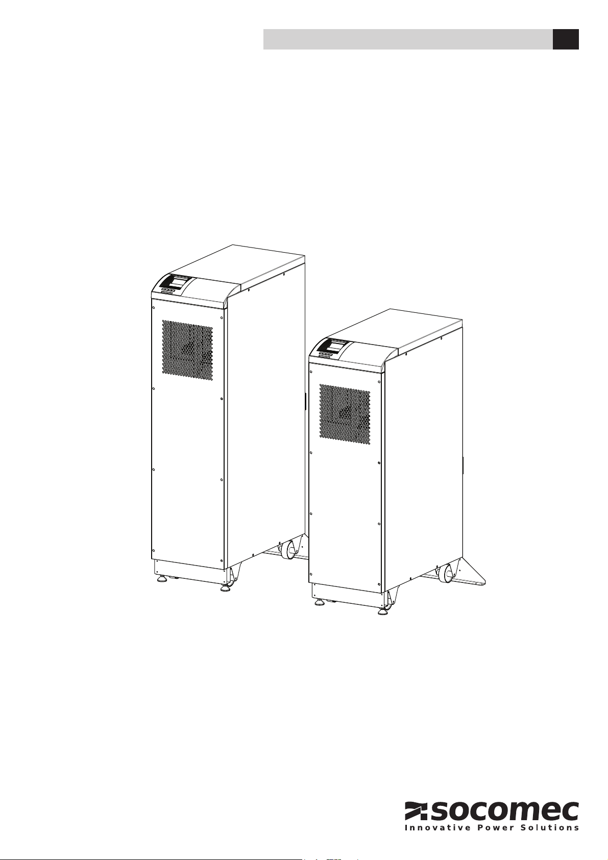
socomec MASTERYS BC+ 10 User manual

MASTERYS BC+
10-20 kVA
INSTALLATION AND OPERATING MANUAL EN

Available installation tutoring mobile app
Discover eWIRE Free download from
Ask your Socomec dealer for your activation code. Visit us at www.socomec.com for more info. (tool page).
This Application is meant to support the User when installing the relevant SOCOMEC products in tutoring the installation step
by step. The Application shall in no way substitute the installation and user manual provided with this SOCOMEC product,
which remains the sole accurate instructions in terms of safety, handling, connection and use of SOCOMEC products.
NOTE!
On starting the unit an operating code is requested.
Before commencing operation, contact an authorised support centre to obtain the code,
providing the unit serial number.
Note that for some options and/or configuration startup should be implemented by quali-
fied technical personnel.

3EN
MASTERYS BC+ 10-20 kVA - IOMMASBCXX0J-EN 00 - SOCOMEC
CONTENTS
1. CERTIFICATE AND CONDITIONS OF WARRANTY 5
2. SAFETY STANDARDS 6
2.1 DESCRIPTION OF SYMBOLS. . . . . . . . . . . . . . . . . . . . . . . . . . . . . . . . . . . . . . . . . . . . . . . . . . . . . . 8
3. ENVIRONMENTAL REQUIREMENTS AND HANDLING 9
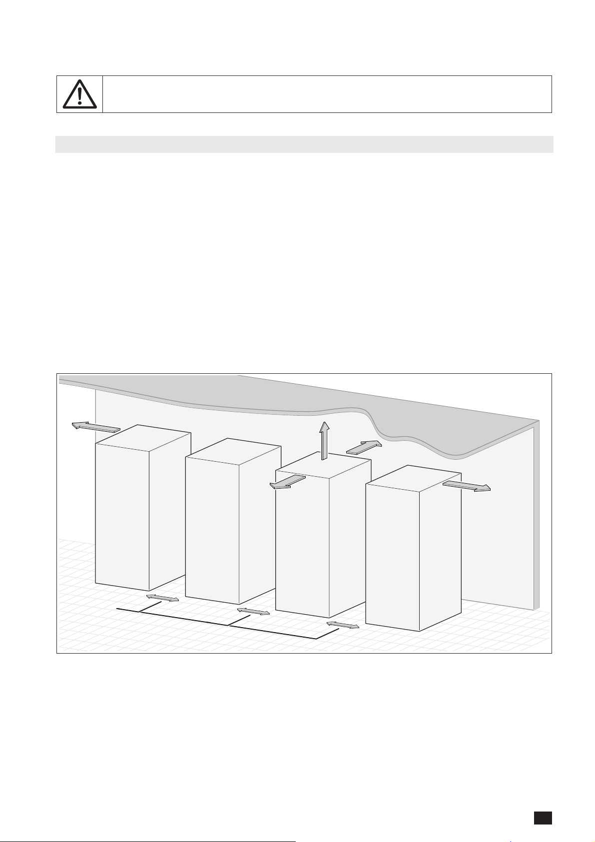
3.1 ENVIRONMENTAL REQUIREMENTS . . . . . . . . . . . . . . . . . . . . . . . . . . . . . . . . . . . . . . . . . . . . . . . . 9
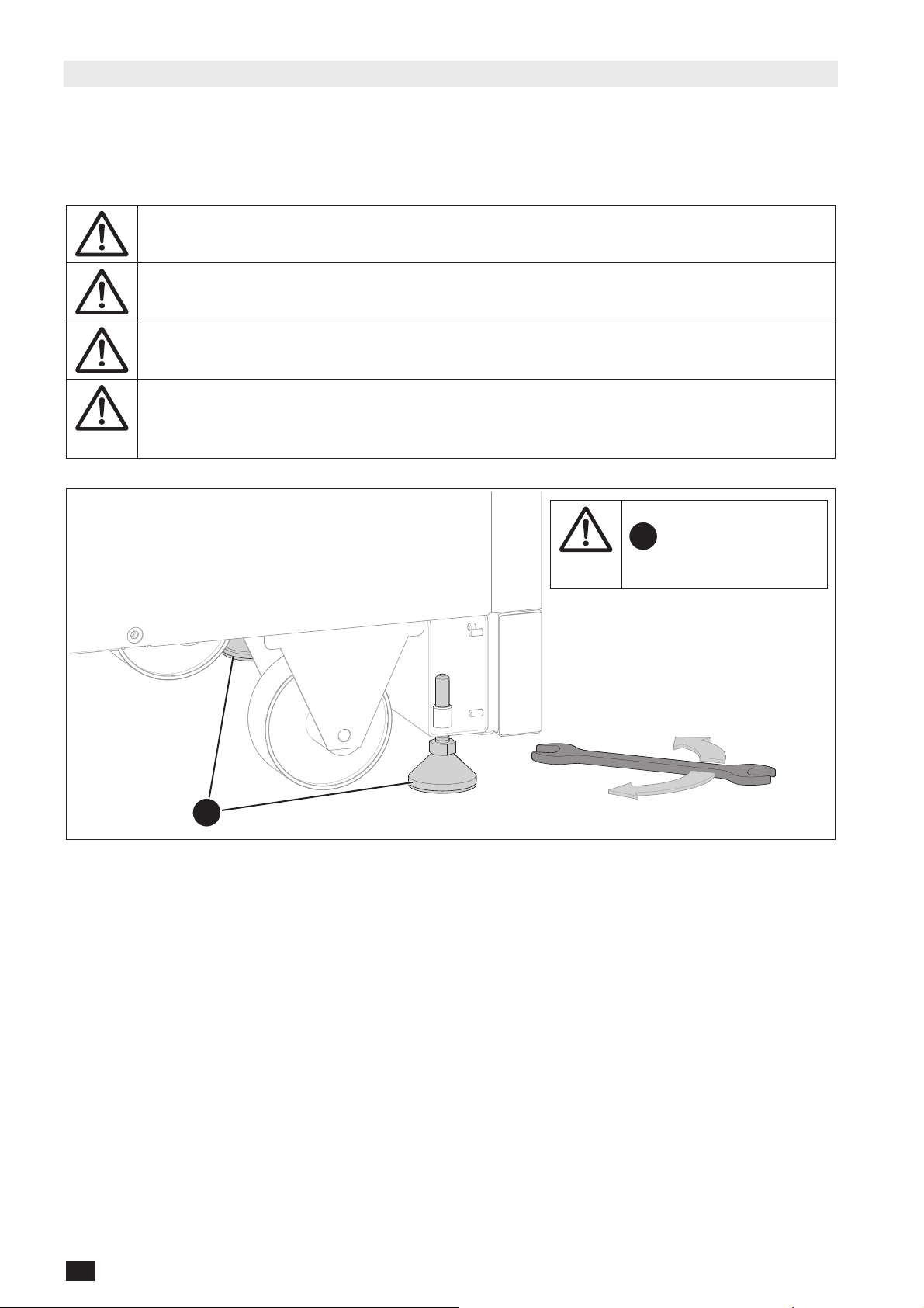
3.2 HANDLING. . . . . . . . . . . . . . . . . . . . . . . . . . . . . . . . . . . . . . . . . . . . . . . . . . . . . . . . . . . . . . . . . . . . 10
4. ELECTRICAL INSTALLATION 11
4.1 UPS SINGLE CONFIGURATION . . . . . . . . . . . . . . . . . . . . . . . . . . . . . . . . . . . . . . . . . . . . . . . . . . . 11
4.1.1 COMMON MAINS (recommended configuration). . . . . . . . . . . . . . . . . . . . . . . . . . . . . . . . . 11
4.1.2 SEPARATE MAINS (recommended configuration) . . . . . . . . . . . . . . . . . . . . . . . . . . . . . . . . 11
4.2 UPS PARALLEL CONFIGURATION . . . . . . . . . . . . . . . . . . . . . . . . . . . . . . . . . . . . . . . . . . . . . . . . 12
4.2.1 GENERAL INFORMATION . . . . . . . . . . . . . . . . . . . . . . . . . . . . . . . . . . . . . . . . . . . . . . . 12
4.2.2 POWER CONNECTIONS . . . . . . . . . . . . . . . . . . . . . . . . . . . . . . . . . . . . . . . . . . . . . . . . 12
4.2.3 COMMON MAINS (recommended configuration). . . . . . . . . . . . . . . . . . . . . . . . . . . . . . . . . 13
4.2.4 SEPARATE MAINS (recommended configuration) . . . . . . . . . . . . . . . . . . . . . . . . . . . . . . . . 14
4.2.5 PARALLEL SETUP RULES. . . . . . . . . . . . . . . . . . . . . . . . . . . . . . . . . . . . . . . . . . . . . . . 15
4.2.6 CONTROL CONNECTIONS . . . . . . . . . . . . . . . . . . . . . . . . . . . . . . . . . . . . . . . . . . . . . . 15
4.3 ELECTRICAL REQUIREMENTS . . . . . . . . . . . . . . . . . . . . . . . . . . . . . . . . . . . . . . . . . . . . . . . . . . . 16
4.4 CABLE POSITIONING . . . . . . . . . . . . . . . . . . . . . . . . . . . . . . . . . . . . . . . . . . . . . . . . . . . . . . . . . . . 22
5. OVERVIEW 23
5.1 FRONT VIEW . . . . . . . . . . . . . . . . . . . . . . . . . . . . . . . . . . . . . . . . . . . . . . . . . . . . . . . . . . . . . . . . . . 23
5.2 REAR SIDE . . . . . . . . . . . . . . . . . . . . . . . . . . . . . . . . . . . . . . . . . . . . . . . . . . . . . . . . . . . . . . . . . . . 24
6. CONNECTIONS 27
6.1 UPS CONNECTION. . . . . . . . . . . . . . . . . . . . . . . . . . . . . . . . . . . . . . . . . . . . . . . . . . . . . . . . . . . . . 28
6.1.1 MAINS AND AUXILIARY MAINS CONNECTED IN COMMON (3/3 models) . . . . . . . . . . 28
6.1.2 MAINS AND AUXILIARY MAINS CONNECTED SEPARATELY (3/3 models). . . . . . . . . . 28
6.1.3 MAINS AND AUXILIARY MAINS CONNECTED SEPARATELY (3/1 models). . . . . . . . . . 28
7. CONTROL PANEL 29
8. MENU 30
8.1 DISPLAY OVERVIEW (SYSTEM) . . . . . . . . . . . . . . . . . . . . . . . . . . . . . . . . . . . . . . . . . . . . . . . . . . . 30
8.2 DISPLAY OVERVIEW (UNIT) . . . . . . . . . . . . . . . . . . . . . . . . . . . . . . . . . . . . . . . . . . . . . . . . . . . . . . 30
8.3 MENU TREE . . . . . . . . . . . . . . . . . . . . . . . . . . . . . . . . . . . . . . . . . . . . . . . . . . . . . . . . . . . . . . . . . . 34
8.4 MENU FUNCTION DESCRIPTIONS . . . . . . . . . . . . . . . . . . . . . . . . . . . . . . . . . . . . . . . . . . . . . . . . 37
8.4.1 ENTERING PASSWORDS . . . . . . . . . . . . . . . . . . . . . . . . . . . . . . . . . . . . . . . . . . . . . . . 37
8.4.2 ALARM MENU . . . . . . . . . . . . . . . . . . . . . . . . . . . . . . . . . . . . . . . . . . . . . . . . . . . . . . . . 37
8.4.3 STATUS MENU. . . . . . . . . . . . . . . . . . . . . . . . . . . . . . . . . . . . . . . . . . . . . . . . . . . . . . . . 37
8.4.4 EVENT LOG MENU . . . . . . . . . . . . . . . . . . . . . . . . . . . . . . . . . . . . . . . . . . . . . . . . . . . . 37
8.4.5 MEASUREMENTS MENU. . . . . . . . . . . . . . . . . . . . . . . . . . . . . . . . . . . . . . . . . . . . . . . . 37
8.4.6 CONTROLS MENU. . . . . . . . . . . . . . . . . . . . . . . . . . . . . . . . . . . . . . . . . . . . . . . . . . . . . 37
8.4.7 USER PARAMS MENU. . . . . . . . . . . . . . . . . . . . . . . . . . . . . . . . . . . . . . . . . . . . . . . . . . 38
8.4.8 SERVICE MENU . . . . . . . . . . . . . . . . . . . . . . . . . . . . . . . . . . . . . . . . . . . . . . . . . . . . . . . 38
9. OPERATING PROCEDURES 39
9.1 SWITCHING ON . . . . . . . . . . . . . . . . . . . . . . . . . . . . . . . . . . . . . . . . . . . . . . . . . . . . . . . . . . . . . . . 39
9.2 SWITCHING OFF. . . . . . . . . . . . . . . . . . . . . . . . . . . . . . . . . . . . . . . . . . . . . . . . . . . . . . . . . . . . . . . 39
9.3 BYPASS OPERATIONS . . . . . . . . . . . . . . . . . . . . . . . . . . . . . . . . . . . . . . . . . . . . . . . . . . . . . . . . . . 40
9.4 EXTENDED OUT OF SERVICE . . . . . . . . . . . . . . . . . . . . . . . . . . . . . . . . . . . . . . . . . . . . . . . . . . . . 41
9.5 EMERGENCY SHUTDOWN. . . . . . . . . . . . . . . . . . . . . . . . . . . . . . . . . . . . . . . . . . . . . . . . . . . . . . . 41
9.6 UPS POWER OFF (U.P.O.) . . . . . . . . . . . . . . . . . . . . . . . . . . . . . . . . . . . . . . . . . . . . . . . . . . . . . . . 41
10. OPERATING MODES 42
10.1 ON LINE MODE . . . . . . . . . . . . . . . . . . . . . . . . . . . . . . . . . . . . . . . . . . . . . . . . . . . . . . . . . . . . . . . . 42
10.2 HIGH EFFICIENCY MODE (ECO MODE). . . . . . . . . . . . . . . . . . . . . . . . . . . . . . . . . . . . . . . . . . . . . 42
10.3 ENERGY SAVER MODE . . . . . . . . . . . . . . . . . . . . . . . . . . . . . . . . . . . . . . . . . . . . . . . . . . . . . . . . . 42
10.4 CONVERTER MODE . . . . . . . . . . . . . . . . . . . . . . . . . . . . . . . . . . . . . . . . . . . . . . . . . . . . . . . . . . . . 43
10.5 OPERATION WITH MAINTENANCE BYPASS. . . . . . . . . . . . . . . . . . . . . . . . . . . . . . . . . . . . . . . . . 43
10.6 OPERATION WITH MOTOR GENERATOR (GENSET) . . . . . . . . . . . . . . . . . . . . . . . . . . . . . . . . . . 43

4EN MASTERYS BC+ 10-20 kVA - IOMMASBCXX0J-EN 00 - SOCOMEC
11. STANDARD FEATURES AND OPTION 44
11.1 STANDARD WEB PAGES . . . . . . . . . . . . . . . . . . . . . . . . . . . . . . . . . . . . . . . . . . . . . . . . . . . . . . . . 45
11.2 ADC+SL CARD . . . . . . . . . . . . . . . . . . . . . . . . . . . . . . . . . . . . . . . . . . . . . . . . . . . . . . . . . . . . . . . . 46
11.2.1 TEMPERATURE SENSOR . . . . . . . . . . . . . . . . . . . . . . . . . . . . . . . . . . . . . . . . . . . . . . . 48
11.3 NET VISION CARD . . . . . . . . . . . . . . . . . . . . . . . . . . . . . . . . . . . . . . . . . . . . . . . . . . . . . . . . . . . . . 49
11.3.1 EMD . . . . . . . . . . . . . . . . . . . . . . . . . . . . . . . . . . . . . . . . . . . . . . . . . . . . . . . . . . . . . . . . 49
11.4 MODBUS TCP CARD . . . . . . . . . . . . . . . . . . . . . . . . . . . . . . . . . . . . . . . . . . . . . . . . . . . . . . . . . . . 49
11.5 BACNET CARD . . . . . . . . . . . . . . . . . . . . . . . . . . . . . . . . . . . . . . . . . . . . . . . . . . . . . . . . . . . . . . . . 49
11.6 REMOTE TOUCHSCREEN DISPLAY . . . . . . . . . . . . . . . . . . . . . . . . . . . . . . . . . . . . . . . . . . . . . . . 50
11.7 PROFIBUS PROTOCOL INTERFACE . . . . . . . . . . . . . . . . . . . . . . . . . . . . . . . . . . . . . . . . . . . . . . . 50
11.8 SOFTWARE OPTION. . . . . . . . . . . . . . . . . . . . . . . . . . . . . . . . . . . . . . . . . . . . . . . . . . . . . . . . . . . . 50
11.9 INTERNAL BACKFEED PROTECTION . . . . . . . . . . . . . . . . . . . . . . . . . . . . . . . . . . . . . . . . . . . . . . 50
11.10 EXTERNAL MAINTENANCE BYPASS. . . . . . . . . . . . . . . . . . . . . . . . . . . . . . . . . . . . . . . . . . . . . . . 50
11.11 KIT FOR TN-C / NEUTRAL-GROUND CONNECTION . . . . . . . . . . . . . . . . . . . . . . . . . . . . . . . . . . 51
11.12 RAMP FOR UPS UNLOADING . . . . . . . . . . . . . . . . . . . . . . . . . . . . . . . . . . . . . . . . . . . . . . . . . . . . 52
11.13 KIT FOR FRONT COVER. . . . . . . . . . . . . . . . . . . . . . . . . . . . . . . . . . . . . . . . . . . . . . . . . . . . . . . . . 53
11.14 KIT FOR FRONT AND LATERAL COVER . . . . . . . . . . . . . . . . . . . . . . . . . . . . . . . . . . . . . . . . . . . . 53
11.15 KIT FOR IP21. . . . . . . . . . . . . . . . . . . . . . . . . . . . . . . . . . . . . . . . . . . . . . . . . . . . . . . . . . . . . . . . . . 53
12. TROUBLESHOOTING 54
12.1 SYSTEM ALARMS. . . . . . . . . . . . . . . . . . . . . . . . . . . . . . . . . . . . . . . . . . . . . . . . . . . . . . . . . . . . . . 54
12.2 SYSTEM STATUS . . . . . . . . . . . . . . . . . . . . . . . . . . . . . . . . . . . . . . . . . . . . . . . . . . . . . . . . . . . . . . 55
13. PREVENTIVE MAINTENANCE 56
13.1 BATTERIES . . . . . . . . . . . . . . . . . . . . . . . . . . . . . . . . . . . . . . . . . . . . . . . . . . . . . . . . . . . . . . . . . . . 56
13.2 FANS & CAPACITORS . . . . . . . . . . . . . . . . . . . . . . . . . . . . . . . . . . . . . . . . . . . . . . . . . . . . . . . . . . 57
14. SAFEGUARDING THE ENVIRONMENT 58
15. TECHNICAL SPECIFICATIONS 59

5EN
MASTERYS BC+ 10-20 kVA - IOMMASBCXX0J-EN 00 - SOCOMEC
1. CERTIFICATE AND CONDITIONS OF WARRANTY
This SOCOMEC continuous power system is guaranteed against any manufacturing or material defects.
The warranty is valid for 12 (twelve) months from the commission date, provided activation is carried out by
SOCOMEC personnel or personnel from a support centre authorised by SOCOMEC, and no more than 15 (fifteen)
months from being shipped from SOCOMEC.
The warranty is valid throughout national territory. If the UPS is exported abroad, the warranty will only cover the parts
used to repair faults.
The warranty is valid ex-works and covers labour and parts used to repair the faults.
The warranty shall not apply in the following cases:
• Failure due to unforeseen circumstances or force majeure (lightning, floods, etc.);
• Failure due to negligence or improper use (use outside limits: temperature, humidity, ventilation, electric power
supply, applied load, batteries);
• Insufficient or inappropriate maintenance;
• When maintenance, repairs or modifications have not carried been out by SOCOMEC personnel, or personnel
from a support centre authorised by SOCOMEC.
• If the battery has not been recharged in accordance with the terms indicated on the packaging and in the manual,
in the event of long periods of storage or UPS inactivity.
SOCOMEC may, at its own discretion, opt for the repair of the product or the replacement of faulty or defective parts
with new parts, or with used parts of equivalent quality to new parts with regard to function and performance.
Defective or faulty parts replaced free of charge must to be made available to SOCOMEC, which becomes the sole
owner.
Replacement or repair of parts, or any modifications to the product during the warranty period, will not extend the
duration of the warranty.
SOCOMEC will not be responsible for damages under any circumstances (including, without limitations, damage for
loss of earnings, interruption of activity, loss of information or other financial losses) arising from the use of the prod-
uct.
These conditions are subject to Italian law. Any disputes fall under the jurisdiction of the Court of Vicenza.
SOCOMEC retains the full and exclusive ownership rights to this document. Only a personal entitlement to use the
document for the application indicated by SOCOMEC is granted to the recipient of this document. The reproduction,
modification, distribution of this document, either partially or wholly and in any manner, is strictly prohibited except
upon Socomec’s express prior written consent.
This document is not a specification. SOCOMEC reserves the right to make any changes to the information provided
without prior notice.

6EN MASTERYS BC+ 10-20 kVA - IOMMASBCXX0J-EN 00 - SOCOMEC
2. SAFETY STANDARDS
This user manual specifies installation and maintenance procedures, technical data and safety instructions for
SOCOMEC. For further information visit the Socomec website: www.socomec.com.
NOTE!
Any work carried out on the equipment must be performed by skilled, qualified technicians.
NOTE!
Before carrying out any operations on the unit read the installation and operating manual care-
fully. Keep this manual safe for future reference.
DANGER!
Failure to observe safety standards could result in fatal accidents or serious injury, and damage
equipment or the environment.
NOTE!
The models are not available for all markets. Contact Socomec for further information.
CAUTION!
If the unit is found to be damaged externally or internally, or any of the accessories are damaged
or missing, contact SOCOMEC. Do not operate the unit if it has suffered a violent mechanical
shock of any kind.
NOTE!
Install the unit in accordance with clearances in order to prevent access to handling devices and
guarantee sufficient ventilation (refer to 'Electrical requirements' chapter).
NOTE!
Only use accessories recommended or sold by the manufacturer.
NOTE!
When the equipment is transferred from a cold to a warm place wait approx. two hours before
putting the unit into operation.
NOTE!
When carrying out electrical installation, all standards applicable specified by the IEC, in particu-
lar IEC 60364, and the electricity supplier must be observed. All national standards applicable to
batteries must be observed. For further information refer to 'Technical specifications' chapter.
WARNING!
Connect the protective earth (PE) conductor before making any other connections.
The UPS requires three-phase plus neutral input connections (3P+N). The neutral input connec-
tion is not required only in case of input transformer.
NOTE!
The installer is responsible for implementing the backfeed protection with the use of AC input
line isolation devices external to the UPS. Refer to 'Electrical requirements' chapter.
DANGER! RISK OF ELECTRIC SHOCK!
Before carrying out any operations on the unit (cleaning and maintenance performances,
connection of appliances, etc.) disconnect all power sources.
DANGER! RISK OF ELECTRIC SHOCK!
After disconnecting all power sources wait approx. 5 minutes for the complete discharge of the
unit.
NOTE!
The UPS may be powered from an IT distribution system with a neutral conductor.

7EN
MASTERYS BC+ 10-20 kVA - IOMMASBCXX0J-EN 00 - SOCOMEC
NOTE!
Any use other than the specified purpose will be considered improper. The manufacturer/
supplier shall not be held responsible for damage resulting from this. Risk and responsibility lies
with the system manager.
NOTE! The product you have chosen is designed for environments that include all commercial, light industry and
industrial establishments other than those directly connected to a low-voltage mains that supplies buildings used for
residential purposes. In order to be used for particular “critical applications” such as life support systems, medical
applications, commercial transportation, nuclear facilities or any other application or systems where product failure
is likely to cause substantial harms to person or property, the products may have to be adapted. For such uses we
would advise you to contact SOCOMEC beforehand to confirm the ability of these products to meet the requested
level of safety, performance, reliability and compliance with applicable laws, regulations and specifications.
WARNING!
Only for 10 kVA 3/3
This is a category C2 UPS product. In a residential environment, this product may cause radio
interference, in which case the user may be required to take additional measures.
For the other models:
This is a product for commercial and industrial application in the second environment - installa-
tion restrictions or additional measures may be needed to prevent disturbances.
Safety requirements for secondary batteries and battery installations.
The installer is responsible for ensuring that the battery installation and their operating environ-
ment conform to national and international codes and safety standards.

8EN MASTERYS BC+ 10-20 kVA - IOMMASBCXX0J-EN 00 - SOCOMEC
2.1 Description of symbols
Symbols Description
Protective earth terminal (PE).
Authorised personnel only.
Only qualified personnel are permitted to work on the batteries.
Do not use naked flames or cause sparks in the vicinity of the accumulators.
No smoking.
Batteries charging!
Batteries and related parts contain lead which is dangerous to health if ingested.
Wash hands after handling!
Accumulators are heavy!
Use suitable transport and lifting equipment to work safely.
Risk of electric shock!
Connecting accumulators in series creates hazardous voltages.
Risk of explosion! Avoid short circuits!
Never place tools or metal objects on the accumulators.
Corrosive liquids (electrolyte).
Read the user instructions carefully.
Read the user manual before performing any operations.
Wear protective gloves
Wear safety shoes.
Wear protective goggles.
In the event of accidents, improper use, failure or electrolyte leakage wear a protective apron.
In the event of accidents, improper use, failure or electrolyte leakage wear a gas mask.
In the event of contact with the eyes, wash immediately with plenty of water and call a doctor.
Call a doctor immediately in the event of accidents or illness.
Do not dispose of in normal waste stream (symbol waste electrical and electronic equipment).

9EN
MASTERYS BC+ 10-20 kVA - IOMMASBCXX0J-EN 00 - SOCOMEC
3. ENVIRONMENTAL REQUIREMENTS AND HANDLING
NOTE!
Before carrying out any operations on the unit read the 'Safety standards' chapter carefully.
3.1 Environmental requirements
The room must be:
• Clean and dry;
• Of a suitable size;
• Free from conductive, inflammable and corrosive items;
• Not exposed directly to sunlight.
The floor must support the weight of the unit and guarantee its stability.
The unit is designed for indoor installation only.
Room positioning
For information regarding ambient temperature, dimensions and weights refer to the 'Technical specifications' chap-
ter.
The connections and the UPS breakers need to be accessible from the rear; a space of at least 1.5 meters should be
left at the front of the UPS for maintenance purposes. It is also advisable to ensure that cable connections are suffi-
ciently long and flexible so that the unit can be extracted during maintenance, if necessary.
A space at least 20 cm must be left at the back for adequate ventilation (see figure).
UPS
OR OTHER
CABINET
UPS
OR OTHER
CABINET
UPS
OR OTHER
CABINET
UPS
Free area:
≥80 cm Free area:
≥60 cm
Free area:
≥20 cm
Free area:
≥60 cm
Free area:
≥30 cm
Free area:
≥150 cm

10 EN MASTERYS BC+ 10-20 kVA - IOMMASBCXX0J-EN 00 - SOCOMEC
3.2 Handling
• The packaging guarantees the stability of the unit during shipping and physical transfer.
• The unit must remain in a vertical position during all shipping and handling operations.
• Ensure that the floor is strong enough to support the weight of the unit.
• Carry the packaged unit as close as possible to the installation site.
The unit MUST be handled by at least two people. The people MUST take position at the sides of
the UPS with respect to the direction of movement.
Do not move the unit by putting pressure on the front.
When moving the unit on even slightly sloping surfaces, use the locking equipment and braking
devices to ensure that the unit does not fall over.
WARNING!
The following instructions must be carried out prior to moving the unit (after initial positioning).
Failure to heed this warning could result in the unit falling over, equipment damage, injury and
even death.
S
Secure the UPS with feet
Sonly when it is in
position with the cable
connected.

11EN
MASTERYS BC+ 10-20 kVA - IOMMASBCXX0J-EN 00 - SOCOMEC
4. ELECTRICAL INSTALLATION
4.1 UPS single configuration
4.1.1 Common Mains (recommended configuration)
X50
A
Q2
X20
X10
Q1 Q5
Q3
A
J
G
MAINS
F
OUT
KEY
ACommon mains thermal-magnetic circuit breaker.
FExternal maintenance bypass switch(1).
GUnit output switch.
JUnit Input mains switch.
UPS
External maintenance bypass(2)
1. Connect signal status to the ADC+sl board.
2. See 'Standard features and option' chapter.
4.1.2 Separate Mains (recommended configuration)
X50
A
Q2
X20
X10 X40
Q1 Q4 Q5
Q3
A
B
I
G
MAINS AUXILIARY
MAINS
F
OUT
KEY
AInput mains thermal-magnetic circuit breaker.
BAuxiliary mains thermal-magnetic circuit breaker.
FExternal maintenance bypass switch(1).
GUnit output switch.
IUnit Auxiliary mains switch.
UPS
External maintenance bypass(2)
1. Connect signal status to the ADC+sl board.
2. See 'Standard features and option' chapter.

12 EN MASTERYS BC+ 10-20 kVA - IOMMASBCXX0J-EN 00 - SOCOMEC
4.2 UPS parallel configuration
4.2.1 General Information
A parallel connection enhances UPS system reliability, performance and power.
Models can be installed in a parallel configuration by specialist personnel using the kit designed for this purpose.
UPS units connected in parallel are fairly similar to a standard UPS unit therefore the safety, shipping and installation
recommendations in the 'Electrical installation' and 'Connections' chapters also apply.
UPS units for parallel operation must comply with the distances indicated in the 'Environmental requirements' chap-
ter.
See the 'Operating procedures' chapter for operating procedures.
4.2.2 Power connections
• See chapter 'Electrical requirements' for input protection devices.
The cross section and length of the input and output cables must be identical for all units.
The phase rotation must be correct and the same for each unit connected in parallel and also on
any external manual bypass line.
Cables of the same length and cross section must be used for connection between general
power switches ( Cand D), switches Aand Band the respective units.
If RCD is installed on the mains power switch (optional), it must be selective and inserted
upstream of the distribution panel, and the trigger value must be 0.5A multiplied by the number
of units connected in parallel (see 'Electrical requirements' chapter).
The cable arrangement for the input, auxiliary and output lines are to be the same for each UPS,
in order to guarantee the same impedance for each power line.
System shutdown switch Hshould always be installed in the external distribution cabinet and
recognised as an emergency shutdown switch (red handle). If this switch is far from the UPS or in
another room a remote shutdown button shall be installed near the UPS.
Before turning on an individual unit ensure that the relevant unit output switch Gis closed.
Before opening unit output switch Gensure that the relevant unit is turned off.
If unit output switches Gare present it is advisable to connect a normally open early break
switch from the switch to the unit’s parallel board.
If an external maintenance bypass switch Fis present it is advisable to connect a normally
closed early make switch from the switch to the parallel board of the concentrator unit.
If a system shutdown switch His present it is advisable to connect a normally open early break
switch from the switch to the parallel board of the concentrator unit.
Communication cables must not exceed 30 metres (made of a specific cable type).
Specific cable type with shield which must be used: F/UTP (or FTP) cat 5e awg 26 100 Ω.

13EN
MASTERYS BC+ 10-20 kVA - IOMMASBCXX0J-EN 00 - SOCOMEC
4.2.3 Common Mains (recommended configuration)
X50 X50 X50
X20
A
Q2
X20
A
Q2
X20
A
Q2
X20
X10 X10 X10
Q1 Q1 Q1Q5 Q5 Q5
Q3 Q3 Q3
C
G
E E
H
G G
F
A A A
MAINS
UPS 1 UPS 2 UPS n
OUT
15 m max15 m max
up to 4 UPSs
KEY
AUnit Input mains thermal-magnetic circuit breaker.
CInput mains thermal-magnetic circuit breaker.
EParallel bus cable.
FExternal maintenance bypass switch(1).
GUnit output switch(2).
HSystem shutdown switch(1).
1. Connect signal status to the parallel board of the concentrator unit.
2. Connect signal status to the unit’s parallel board.

14 EN MASTERYS BC+ 10-20 kVA - IOMMASBCXX0J-EN 00 - SOCOMEC
4.2.4 Separate Mains (recommended configuration)
X50 X50 X50
A
Q2
X20
A
Q2
X20
A
Q2
X20
X10 X10 X10
X40 X40 X40
Q1 Q1 Q1Q4 Q4 Q4Q5 Q5 Q5
Q3 Q3 Q3
C
G
E E
H
G G
F
B
A
B
A
B
A
D
MAINS AUXILIARY MAINS
UPS 1 UPS 2 UPS n
OUT
15 m max15 m max
15 m max
up to 4 UPSs
KEY
AUnit Input mains thermal-magnetic circuit breaker.
BUnit Auxiliary mains thermal-magnetic circuit breaker.
CInput mains thermal-magnetic circuit breaker.
DAuxiliary mains thermal-magnetic circuit breaker.
EParallel bus cable.
FExternal maintenance bypass switch(1).
GUnit output switch(2).
HSystem shutdown switch(1).
1. Connect signal status to the parallel board of the concentrator unit.
2. Connect signal status to the unit’s parallel board.

15EN
MASTERYS BC+ 10-20 kVA - IOMMASBCXX0J-EN 00 - SOCOMEC
4.2.5 Parallel setup rules
In order to achieve the best performance in a parallel configuration ensure that the mains input, output and auxiliary
input cables:
• Have the same length (maximum length range is ±5%).
• Are as short as possible.
• Are not longer than 15 metres.
• Are arranged evenly and not wrapped in coils. Cabling must be the same for each UPS in parallel.
WARNING!
In a parallel system it is necessary to oversize the auxiliary input cables at least 20% more than
the rated value, due to the auxiliary input current balance tolerances.
4.2.6 Control connections
Control cables Eare required for units connected in a parallel configuration.
The control cables are supplied with the UPS in the case of standard parallel arrangements, or attached to the paral-
lel kit if the system is upgraded at a later date.
The control cables supplied allow a maximum distance of about 1/2 meter between the UPS units.
Furthermore, every individual unit must read the status of its output switch, and one of the two units, known as the
concentrator, must read the status of the external manual bypass of the system Fand the status of the output
switch of the system H.
Parallel configuration must only be activated by qualified SOCOMEC personnel; in each case arrange the control
cables in the relevant cable run as shown in the diagram, leaving the connector(s) unconnected (one incoming and
one outgoing control cable must be used).

16 EN MASTERYS BC+ 10-20 kVA - IOMMASBCXX0J-EN 00 - SOCOMEC
4.3 Electrical requirements
NOTE!
Before carrying out any operations on the unit read the 'Safety standards' chapter carefully.
The installation and system must comply with national plant regulations.
The electrical distribution panel must have a sectioning and protection system installed for input and auxiliary mains.
Ensure a type-B RCD (residual current detector) is installed on the mains power switch and that this is inserted
upstream of the distribution panel.
Size of input protection devices
Model rating Magneto-thermal
input(1)
Magneto-thermal
Auxiliary Mains(1) Differential input(3) Internal battery
protection(4)
(kVA) In/Out
phase
(A) (A) (A) (A)
A B
Selective type
Fuse
Single unit Parallel (n)
(n = 1 up to 4)
10
3/1
25 80 0.5 0.5*n 50 aR
15 32 100 0.5 0.5*n 100 aR
20 40 125 0.5 0.5*n 100 aR
10
3/3
25 25 0.5 0.5*n 50 aR
15 32 32 0.5 0.5*n 100 aR
20 40 40 0.5 0.5*n 100 aR
Cable core size
Model rating
Type of cable
core size
Input cable
core size Auxiliary cable core size(2) Output cable core size(2)
(kVA) In/Out
phase
mm2(AWG) mm2(AWG) mm2(AWG)
flexible cable flexible cable flexible cable
10
3/1
min 6 (AWG10) 16 (AWG5) 16 (AWG10)
max(5) 25 (AWG3) 25 (AWG3) 25 (AWG3)
15 min 6 (AWG10) 25 (AWG3) 25 (AWG10)
max(5) 25 (AWG3) 25 (AWG3) 25 (AWG3)
20 min 10 (AWG7) 25 (AWG3) 25 (AWG7)
max(5) 25 (AWG3) 25 (AWG3) 25 (AWG3)
10
3/3
min 6 (AWG10) 6 (AWG10) 6 (AWG10)
max(5) 25 (AWG3) 25 (AWG3) 25 (AWG3)
15 min 6 (AWG10) 6 (AWG10) 6 (AWG10)
max(5) 25 (AWG3) 25 (AWG3) 25 (AWG3)
20 min 10 (AWG7) 10 (AWG7) 10 (AWG7)
max(5) 25 (AWG3) 25 (AWG3) 25 (AWG3)
1. Recommended thermal-magnetic circuit breaker: with intervention threshold Curve C, it is necessary to use a D curve
selective breaker in case of UPS with transformer. For backfeed protection use a magneto thermal switch with 220 V - 240 V
release coil.
2. For parallel configuration, cables shall have the same size and length for each unit (maximum length tolerance is ±5%).
Output cables should be less than 15 metres.
3. Use a single type-B selective (S) breaker installed upstream of the inputs power supply.
4. See "5.2 Rear side" chapter.
5. Determined by the size of the terminals.

17EN
MASTERYS BC+ 10-20 kVA - IOMMASBCXX0J-EN 00 - SOCOMEC
CAUTION: Residual Current Detection (RCD) can only be used when mains and auxiliary mains
are connected together (configuration not recommended). It must be placed upstream of the
connection between the mains and auxiliary mains. If RCD is installed the trigger value must be
0.5 A multiplied by the number of units connected in parallel.
Use type B four-pole selective (S) residual current detectors. Load leakage currents are to be
added to those generated by the UPS and during transitory phases (power failures and power
returns) short current peaks may occur. If loads with high leakage current are present, adjust
the residual current protection. It is advisable in all cases to carry out a preliminary check on the
earth current leakage with the UPS installed and operational with the definitive load, so as to
prevent the RCD tipping over.
Ensure personal protection against indirect contact, bearing in mind that there is RCD protection
with a high trigger current upstream of the UPS units, as recommended above.
The phase rotation of auxiliary mains and output cables must be the same for each unit.
NOTE:
- 3/1: to ensure bypass integrity select an appropriate auxiliary magneto thermal switch to limit I2t to
maximum 14.4 kA2s and peak current to maximum 2.4 kA for 10 ms.
- 3/3: to ensure bypass integrity select an appropriate auxiliary magneto thermal switch to limit I2t to
maximum 7.2 kA2s and peak current to maximum 1,2 kA for 10 ms.
Contact SOCOMEC for detailed information.
The UPS is designed for transient overvoltages in category II installations. If the UPS is part of
the building’s electrical circuit, or is likely to be subject to transient overvoltages in category
III installations, additional external protection must be provided, either on the UPS or in the AC
power supply network powering the UPS.
The UPS is designed for indoor environmental service conditions according to IEC 60721-
3-3 with pollution degree lower or equal to 2 (non-conductive pollution).
WARNING: as specified in EN62040-3 Appendix 3: Non-linear Load Reference, in the event of
three-phase non-linear loads connected downstream of the UPS, the neutral current on the load
can be 1.5 - 2 times higher than the phase current. This must be considered when estimating the
correct size of the output and the auxiliary neutral cables.
WARNING: protective earthing conductor (PE) must have sufficient current-carrying capacity.
The PE cable core size must be chosen according to the PROTECTIVE CURRENT RATING of the
earth circuit which depends on the provision and location of protective overcurrent devices.
We suggest 16 mm2(AWG4) for MASTERYS BC+ 3/3 version and 25 mm2(AWG2) for MASTERYS
BC+ 3/1 version using the protective devices in the table above.
NOTE: 3-Phase 4-Wire Input Power is required.
The unit can be installed in TN-C, TN-S, TT and IT AC distribution systems (IEC 60364-3).
For TN-C system see 'External backfeed protection' chapter.
Contact SOCOMEC for detailed information.

18 EN MASTERYS BC+ 10-20 kVA - IOMMASBCXX0J-EN 00 - SOCOMEC
External backfeed protection
The UPS is set up for the installation of external protection devices against dangerous voltage backfeed on both
the input power supply line (MAINS SUPPLY) and the auxiliary backup mains power supply line (AUXILIARY MAINS
SUPPLY); these devices are controlled by dedicated outputs (X29 and X28).
The current rating of the switching device has to follow the instruction outlined in chapter 'Electrical requirements'.
DANGER! RISK OF ELECTRIC SHOCK!
The installer must attach the warning label in order to warn electrical technicians about danger-
ous backfeed situations (not caused by the UPS).
The label must be affixed:
• to all primary power isolators installed remotely from the UPS area;
• to all external access points, if present;
• between the isolators and the UPS.
Warning label (supplied with the equipment) Backfeed trip coil wiring
Before working on this circuit
- Isolate the Uninterruptible Power System (UPS)
- Then check for Hazardous Voltage between all terminals
including the protective earth
Risk of Voltage Backfeed
L1
COM1/COM2
NC1/NC2
L2
L3
N
U
>
Backfeed trip coils supply
XB28 XB29
XB28 XB29
Not present in case
of internal back-
feed.

19EN
MASTERYS BC+ 10-20 kVA - IOMMASBCXX0J-EN 00 - SOCOMEC
NOTE!
Use a 220-240 V trip coil with integrated travel limit contact to pilot the input/auxiliary protection
systems. If a trip coil without an integrated end of travel contact is used, a normally open early
break contact must be added (see 'Backfeed trip coil wiring' diagram). Electrical contact data:
1.6 A 250 V AC.
Function Connector name Voltage Internal fuse Detail
BKF AUX X29 220-240 V rms 1.6 A time delay COM 2(1)
NC2
BKF MAINS X28 220-240 V rms 1.6 A time delay COM1(1)
NC1
1. COM1 and COM2 are connected to the neutral.

20 EN MASTERYS BC+ 10-20 kVA - IOMMASBCXX0J-EN 00 - SOCOMEC
• Common Mains
Activating UPS protection on the mimic panel: access the MAIN MENU > SERVICE > LED TEST > MAINS
CONFIGURATION and set the parameter to COMMON MAINS.
3/3 models
A
T1
L1
L2
L3
N
X10
L1
L2
L3
N
XB28
XB29
U
>
MAINS
UPS
BKF
Key
ADistribution panel
U
>
Shunt trip coil
X10 Mains terminal block
X40 Auxiliary Mains terminal block
T1 Mains BKF power isolation device
X29 Not connected
X28 Mains BKF terminals
Remote switches – rated current
Model T1 (A)
10 3/3 25
15 3/3 32
20 3/3 40
This manual suits for next models
2
Table of contents
Other socomec Power Supply manuals
Popular Power Supply manuals by other brands

MKS
MKS 246C instruction manual

Lambda Electronics
Lambda Electronics 71 instruction manual

TDK-Lambda
TDK-Lambda HWS 30A-150A/ME Series instruction manual

Aqprox Gaming
Aqprox Gaming APP700PS user guide

Lucent Technologies
Lucent Technologies Lineage 2000 product manual

Tektronix
Tektronix PS 5004 instruction manual