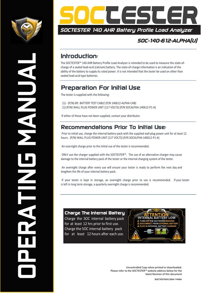
SOCTESTER SOC AERO User manual

Uncontrolled Copy when printed or downloaded.
Please refer to the SOCTESTER™ website address below for the
latest Revision of this document
SOCTESTER.COM/AERO-70M
OPERATING MANUAL
Introduction:
The SOC AERO Battery Profile Load Analyzer is intended to be used as directed in this manual. It is not intended
that the tester be used on any other than the specific type of battery it was designed to test. Customization,
including Preprogrammed AHR and Voltage settings, is available upon request.
SOCTESTER
SOCTESTER AERO Battery Profile
Load Analyzer
SOC-AERO-70-ALPHA
Preparation For Initial Use
The tester is supplied with the following:
(1) - 6ft. BATTERY TEST CABLE (P/N SOC-AERO-70-ALPHA-CAB)
(1) - WALL PLUG POWER UNIT (117 VOLTS) (P/N SOC-AERO-70-P1-A)
If either of these items have not been supplied, contact your distributor.
Recommendations Prior To Initial Use:
Prior to initial use, charge the internal battery pack with the supplied wall plug power unit for at least 12
hours. Charger -> WALL PLUG POWER UNIT (117 VOLTS) (P/N SOC-AERO-70-P1-A)
An overnight charge prior to the Initial use of the tester is recommended.
ONLY use the charger supplied with the SOCTESTER™. The use of an alternative charger may cause
damage to the internal battery pack of the tester or the internal charging system of the tester.
An overnight charge after every use will ensure your tester is ready to perform the next day and
lengthen the life of your internal battery pack.
If your tester is kept in storage, an overnight charge prior to use is recommended. If your tester
is left in long term storage, a quarterly overnight charge is recommended.
Charge The Internal Battery
Charge the SOC internal battery pack
for at least 12 hrs prior to first use.
Charge the SOC internal battery pack
for at least 12 hours after each use.

SOC TESTER ALPHA Series SOC-AERO-70-ALPHA
1. Introduction ............................................................................................................... 1
2.
3.Main Settings Screen -Step By Step Instructions .......................................................... 3
3. (a) Main Settings Screen - Connect And Power Up .................................................. 3
3. (b) Main Settings Screen - AHR Setting .................................................................... 4
3. (c) Main Settings Screen - Automatic Variable Recognition Settings ........................ 5
4.Interpreting Results Step-By-Step Instructions .......................................................... 6
© 2019 SOC Tester Page 2of 11 SOCTESTER.COM/AERO-70M
LIMITED WARRANTY
THE SOCTESTER™ BATTERY TESTER IS GUARANTEED AGAINST DEFECTS IN MATERIALS
AND WORKMANSHIP FOR 90 DAYS FROM THE DATE OF PURCHASE. ULTRASYSTEMS
ELECTRONICS INC. WILL, AT ITS OPTION, REPAIR OR REPLACE DEFECTIVE PARTS OR UNITS.
THE PURCHASER AGREES TO ASSUME ALL RESPONSIBILITY FOR DAMAGES OR BODILY
INJURY THAT MAY RESULT FROM THE USE OR MISUSE OF THIS TESTER BY THE
PURCHASER, ITS EMPLOYEES OR AGENTS. UNDER NO CIRCUMSTANCES SHALL
ULTRASYSTEMS ELECTRONICS INC. BE RESPONSIBLE FOR CONSEQUENTIAL DAMAGES.
THIS WARRANTY IS IN LIEU OF ALL OTHER WARRANTIES- EXPRESSED OR IMPLIED.
WARNING
THIS TESTER IS INTENDED FOR USE BY QUALIFIED PERSONNEL ONLY. IT IS IMPORTANT
THAT OPERATORS OF THIS EQUIPMENT FOLLOW THE OPERATING INSTRUCTIONS
CAREFULLY. PROPER BATTERY HANDLING PROCEDURES ARE MANDATORY AND THE
MANUFACTURER’S INSTRUCTIONS MUST BE OBSERVED.
SOCTESTER 70 AHR Battery Profile Load Analyzer SOC-AERO-70-ALPHA
5.Tips For Successful Use ............................................................................................. 8
6.Internal Battery Maintenance ................................................................................... 9
Specifications .......................................................................................................... 10
8.Condensed Operation Manual ................................................................................. 11
4. (a) Interpreting Results -The Results Screen ............................................................ 6
4. (b) Interpreting Results - Percentage Breakdown ................................................... 7
Table Of Contents ........................................................................................................ 2
6.

CONNECT TEST CLIPS
Install the battery cable set into the mating connector on the right side panel of the tester.
Rotate the lock ring until the connector is firmly seated.
Connect the black battery clip to the NEGATIVE (-) terminal on the battery.
Connect the red battery clip to the POSITIVE (+) terminal on the battery.
Ensure the battery clip connections are secure and have made a good electrical connection.
TURN ON THE BREAKER
After the cable set connection is secure, turn on the breaker and power up the tester.
IMPORTANT NOTE: !The tester will not turn on, UNTIL the cable set is connected to the battery under test!
SOCTESTER 70 AHR Battery Profile Load Analyzer SOC-AERO-70-ALPHA
© 2019 SOC Tester Page 3of 11 SOCTESTER.COM/AERO-70M
Step-By-Step Instructions:
IMPORTANT: In order to turn on the tester, you must first connect to the battery under test.
!The tester will not turn on, unless the cable set is connected to the battery under test!
SOC TESTER ALPHA Series SOC-AERO-70-ALPHA
SIMPLE INSTUCTIONS - FRONT AND CENTER
Simple Instructions are displayed on the center of the front panel when
you open the tester.
The use of the tester is extremely straight forward, but the detailed step
by step instructions below should provide the end user with ultimate
clarity by breaking down every step in great detail.
Step One: Connect Test Cable Set And Turn On The Breaker

MANUAL INPUT:
AHR (AMPERE HOUR RATING) VARIABLE
This is the only manual input required by the end user.
(*Pre-Programmed Option Available - Requiring No Manual Input and
thus eliminating end user error)
Set the AHR (ampere hour rating) for the battery under test by
adjusting the AHR knob to the clockwise or counter-clockwise to reach
the required test variable for the battery under test.
The AHR (ampere hour rating) knob is found in the center of the
control panel, directly under the display screen.
The AHR (ampere hour rating) should be based on the standard 20 hour
rate. This information can usually be found on the battery label.
MAIN SETTINGS SCREEN
Turn on the breaker, while connected to the battery under test,
and the main settings screen will be displayed.
The Main Settings Screen will allow the end user to input and/or verify automatically recognized variables for the test
sequence. There is only 1 manual input required by the end user, the AHR setting variable, making the tester extremely simple
to operate. *Pre-programmed AHR variables are available upon request.
SOC TESTER ALPHA Series SOC-AERO-70-ALPHA
MAIN SETTINGS SCREEN
This is the Main Settings Screen that will be displayed when
powering up the tester.
This screen will give the end user a full view of the test variables.
TEST VARIABLES:
TEMP SETTING - VOLTS SETTING - AHR SETTING
The OCV (Open Circuit Voltage) is also displayed above the
"VOLTS" setting on the right side of the screen. The end user may
view the starting OCV (Open Circuit Voltage) of the battery prior
to test.
Step Two: Set The AHR (Ampere Hour Rating)
© 2019 SOC Tester Page 4of 11 SOCTESTER.COM/AERO-70M
SOCTESTER 70 AHR Battery Profile Load Analyzer SOC-AERO-70-ALPHA

2019 SOC Tester© Page 5of 11 SOCTESTER.COM/AERO-70M
SOC TESTER ALPHA Series SOC-AERO-70-ALPHA
AUTOMATIC VOLTAGE VARIABLE
RECOGNITION - AVR
AUTOMATIC VOLTAGE VARIABLE RECOGNITION - AVR is engaged by
default and will automatically select the required voltage variable of
the battery under test.
The OCV (Open Circuit Voltage) of the battery under test will also be
displayed above the battery test voltage setting.
This variable is completely automatic and there is no manual input
required or allowed for this variable.
*IMPORTANT NOTE: IF you are testing a 24V battery and the
AUTOMATIC VOLTAGE RECOGNITION selects 12V,
DO NOT RUN THE TEST as the 24V battery has fallen to the 12V
range and is would be considered a bad battery.
AVR - ATR - INPUT SETTINGS
AUTOMATIC VARIABLE RECOGNITION
Step Three: Start The Test Cycle
AUTOMATIC INPUT:
TEMP VARIABLE RECOGNITION AVR
+Plus OPTIONAL TEMP OVERRIDE
The Temperature of the battery under test will be recognized
automatically and the variable will automatically be set for the test
sequence.
This input is completely automatic, however, the temp setting
allows for an optional manual override of the temperature variable.
Adjusting the left knob labeled Temp OR on the SOC control panel
clockwise or counter-clockwise will override temperature and allow
the user to set the required input variable.
Press The Start Button
Press the start button on the right side of the control panel to start the test cycle. At the end of the 43 second load cycle, the
battery tester will beep and the True-state-of-charge and capacity of the battery under test will be revealed.
SOCTESTER 70 AHR Battery Profile Load Analyzer SOC-AERO-70-ALPHA

© 2019 SOC Tester Page 6of 11 SOCTESTER.COM/AERO-70M
SOC TESTER ALPHA Series SOC-AERO-70-ALPHA
Interpreting Results
SOCTESTER 70 AHR Battery Profile Load Analyzer SOC-AERO-70-ALPHA
The Results Screen
When the test has been completed, the tester will beep and the results will be broken down on the control panel display. The start
button LED will also be illuminated indicating the state-of-charge of the battery Green-Pass/Yellow-Marginal/Red-Fail. The battery
backdrop will also show Green-Pass/Yellow-Marginal/Red-Fail depending on the results of the test cycle.
Quick Results Reference:
When the load test cycle has completed, the tester will beep and the results will be broken down on the control
panel display.
The start button LED will illuminate indicating the state-of-charge of the battery along with the corresponding
PASS - MARGINAL - FAIL written results shown on the Control panel display with corresponding background colors.
GREEN = (GOOD/PASS) -
YELLOW = (MARGINAL) -
RED = (FAIL/BAD) -
The "ACTUAL AHR" (Ampere Hour Calculation) of the battery under test, based on the resulting TSOC value, will be
calculated and written to the display. The Ampere Hour Calculation provides the end user with real time insight into
the battery under test for on the spot decision making without the end user having to perform calculations.
RESULTS SCREEN BREAKDOWN
Quick View Results are
Displayed On The Right
A quick view and reference of
the testing cycle results will be
displayed on the right.
Capacity results will be displayed
in a numerical percentage %
format.
Results will be written and color
coded in Green-Pass/Yellow-
Marginal/Red-Fail depending on
the results of the test cycle.
Detailed Results Are Displayed In The Center
A detailed breakdown of the test results are displayed in the center of the
screen. "TSOC Results" percentage results are shown center left as well as
a written and color coded Green-Pass/Yellow-Marginal/Red-Fail on Center.
The "ACTUAL AHR" (Ampere Hour Calculation) of the battery under test is
found -center right- with the manual input AHR Setting directly above
"ACTUAL AHR" for quick and direct reference to the calculation.
Test Variables Are
Displayed On The Left
All the test variables are displayed
on the left side of the screen under
"SETTINGS".
Voltage (AUTO)
AHR setting (MANUAL INPUT, OR PRE-PROG)
Temp Setting (AUTO, OR OVERRIDE)
OCV [Open Circuit Voltage] (AUTO)
Battery Chemistry (AUTO)
These are the test variables for the
completed test cycle as manually
input and/or auto input.

© 2019 SOC Tester Page 7of 11 SOCTESTER.COM/AERO-70M
SOC TESTER ALPHA Series SOC-AERO-70-ALPHA
Percentage Breakdown
TSOC % And Actual AHR Calculation
SOCTESTER 70 AHR Battery Profile Load Analyzer SOC-AERO-70-ALPHA
105%-110% (GREEN) This is a normal state-of-charge for many systems. It merely indicates the battery will yield energy
exceeding the 20-hour rating. Some batteries, under ideal conditions, improve with age. Test twice.
100%-105% (GREEN) This is the normal state-of-charge and indicates the battery will deliver 100% of its rated capacity
90% (GREEN) Even new batteries may read 90%. The capacity of a new battery can improve with time however, and may later
read 100%. This battery should be monitored to ensure further loss of battery capacity does not occur.
80% (YELLOW) A battery that reads 80% is considered to be marginal for normal use. Ensure the charging system for the
battery is working correctly.
70% (YELLOW) A 70% indication means the battery no longer has sufficient capacity for normal use. If the charging system is
working properly, the battery should be replaced. In use, it may yield erratic or unreliable performance.
60% and below (RED) A reading of 60% and below, on a properly charged battery, indicates the battery needs to be
replaced.
Batteries that read 40% and below are usually not salvageable.
The tester will interrupt the load cycle of dead or almost dead batteries before 43 seconds. The tester will not run its complete load cycle
on a dead battery. If you have made the connections correctly and the tester does not complete the load cycle, or even turn on, your
battery is probably completely dead.
Batteries removed from storage that read less than 100%, but more than 50%, may need a precise recharge cycle to restore original
capacity. These batteries should be float charged on precision automatic equipment for a minimum of 24 hours.
TSOC Percentage Break Down:

© 2019 SOC Tester Page 8of 11 SOCTESTER.COM/AERO-70M
SOC TESTER ALPHA Series SOC-AERO-70-ALPHA
Successful Operation
SOCTESTER 70 AHR Battery Profile Load Analyzer SOC-AERO-70-ALPHA
*Important Tips And Recommendations For Proper Use:
It is important all of the terminals of the battery being tested be clean.
It is important the battery test clips are clean and not damaged. A thin coating of
petroleum jelly (Vaseline) is recommended.
Do not block the cooling fans of the SOCTESTER™ battery tester. It is important air
flows freely through the battery tester panel.
The Test cables have been specially designed and must not be modified or altered in
any way. Make certain the test cables of the tester are connected directly to the
terminals of the battery.
Batteries that are connected in series should be tested individually, if possible.
Do not connect the tester to a battery larger than the working capacity of the tester.
Tips And Best Practices

© 2019 SOC Tester Page 9of 11 SOCTESTER.COM/AERO-70M
SOC TESTER ALPHA Series SOC-AERO-70-ALPHA
Internal Battery Pack Maintenance
INTERNAL BATTERY CHARGING
SOCTESTER 70 AHR Battery Profile Load Analyzer SOC-AERO-70-ALPHA
“Internal Battery Low”
If the “Internal Battery Low” indicator comes on during use, the internal battery pack needs to be recharged.
Follow the directions on the display.
Charging Notes and Recommendations
The tester may be used with the internal battery Pack charger plugged in, but if the tester has reached maximum battery pack discharge and
the “Internal Battery Low” screen is displayed, it is recommended to immediately turn of the tester, disconnect the tester from the external
battery under test and plug in the wall charger while the tester is disconnected from any external battery.
The tester should remain disconnected from any external batteries, in the off position, with the wall charger plugged into the tester for at
least 15 minutes of charge time prior to continuing to test batteries with the charger plugged into the tester.
Prior to initial use, charge
the internal battery pack
Prior to initial use, charge the internal battery pack
with the supplied wall plug power unit for at least 12
hours. (P/N) WALL PLUG POWER UNIT (117 VOLTS)
(P/N SOC-AERO-70-P1-A)
An overnight charge prior to the Initial use of the
tester is recommended.
The "INTERNAL BATTERY CHARGE IN PROGRESS" Led will be illuminated during battery pack charging. The "MAINTENANCE MODE/CHARGE
COMPLETE" Led will illuminate gradually when the system is reaching full charge and be at full brightness in maintenance mode when the
charge is complete.
The AC power unit may be plugged in for extended periods of time if desired and
overnight charging is recommended before every use and after every use.
An overnight charge after every use will ensure your tester is ready to perform the
next day and lengthen the life of your internal battery pack.
If your tester is kept in storage, an overnight charge prior to use is recommended. If
your tester is left in long term storage, a quarterly overnight charge is recommended.
ONLY use the SOCTESTER™ charger supplied with the SOCTESTER™. The use of an
alternative charger may cause damage to the internal battery pack of the tester or the
internal charging system.

© 2019 SOC Tester Page 10of 11 SOCTESTER.COM/AERO-70M
SOC TESTER ALPHA Series SOC-AERO-70-ALPHA
Specifications
SOC-AERO-70-ALPHA
SOCTESTER 70 AHR Battery Profile Load Analyzer SOC-AERO-70-ALPHA
SPECIFICATIONS:
VOLTAGE: 12V, 24V (Customization Available)
AMPERE HOUR RATING: 3-70 AH (Customization Available)
SHIPPING WEIGHT: 20.5 lb.
SIZE: 14.9" X 12.1" X 9.6"
OPTIONS & REPLACEMENT PARTS
6ft. BATTERY TEST CABLE
(P/N SOC-AERO-70-ALPHA-CAB)
(*Custom Cable Sets Are Available)
WALL PLUG POWER UNIT (117 VOLTS)
(P/N SOC-AERO-70-P1-A)

© 2019 SOC Tester Page 11of 11 SOCTESTER.COM/AERO-70M
SOC TESTER ALPHA Series SOC-AERO-70-ALPHA
Step By Step {CONDENSED}
CONDENSED OPERATIONAL MANUAL
SOCTESTER 70 AHR Battery Profile Load Analyzer SOC-AERO-70-ALPHA
STEP ONE: Make Connections
Install the battery cable into the mating connector on the right side of the tester.
Connect the black battery clip to the NEGATIVE (-) terminal of the battery.
Connect the red battery clip to the POSITIVE (+) terminal of the battery.
*IMPORTANT NOTE: If the battery to be tested is connected to equipment, disconnect the
battery connections following the manufacturer’s recommendations. This is important, because
some batteries are biased to unusual or unexpected voltages.
STEP TWO: Set the “Ampere Hour”
Set the “Ampere Hour” knob to the ampere hour rating of the battery being tested.
*The ampere hour rating should be based on the standard 20 hour rate.
*Ampere hour rating information can usually be found on the battery label.
STEP THREE: Start The Test
Verify Setting Variables and Depress the “Start Test” button momentarily.
The tester start the load cycle indicating the test has begun.
RESULTS:
At the end of 43 second load cycle, the the cooling cycle will begin and the results of the test
will be shown for the duration of the cooling cycle on the control panel display.
This manual suits for next models
1
Table of contents
Other SOCTESTER Measuring Instrument manuals
