Sofar 7.5KTLM User manual

SOFAR 7.5KTLM User manual
Copyright © Shenzhen SOFARSOLAR Co., Ltd
I
Contents
Preface..................................................................................................................................... III
1. Basic safety information................................................................................................... - 1 -
1.1. Safety instructions...............................................................................................- 1 -
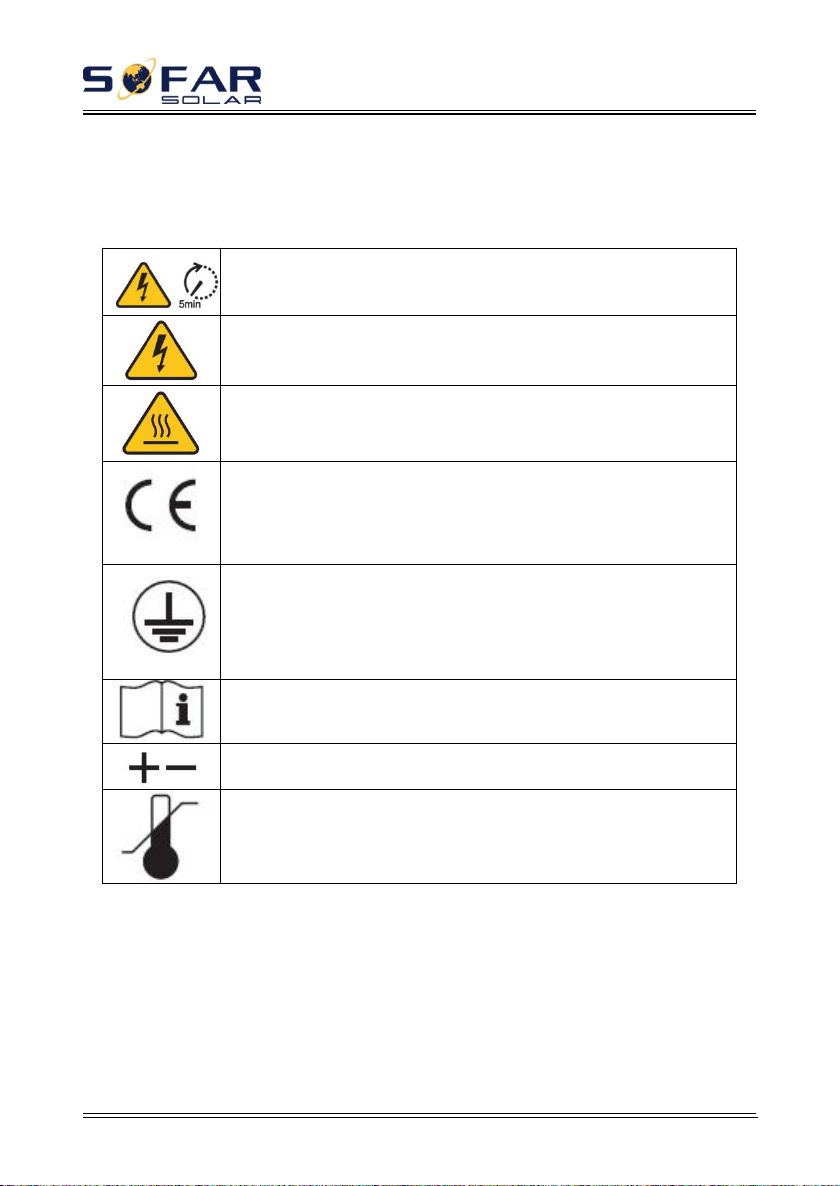
1.2. Symbols and signs...............................................................................................- 4 -
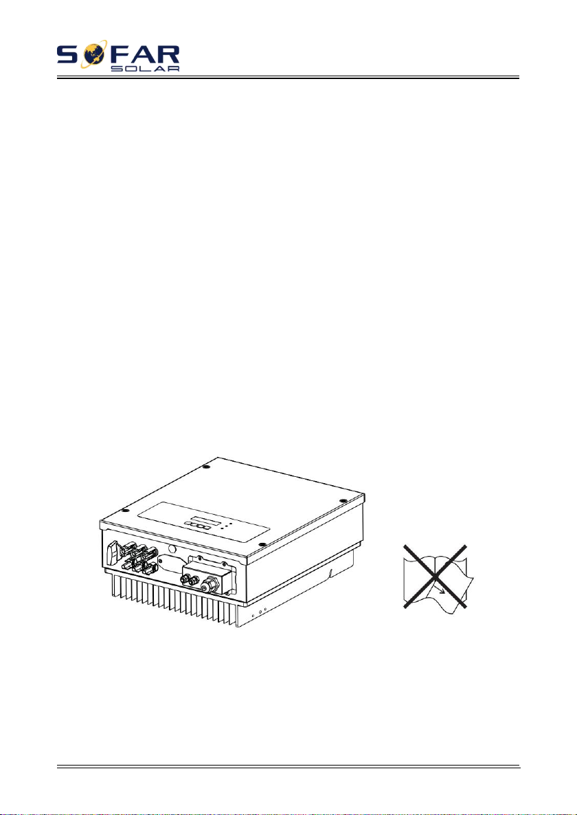
2. Product characteristics...................................................................................................... - 6 -
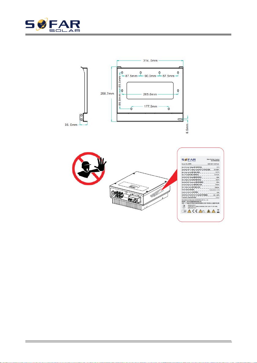
2.1. Product dimensions............................................................................................. - 6 -
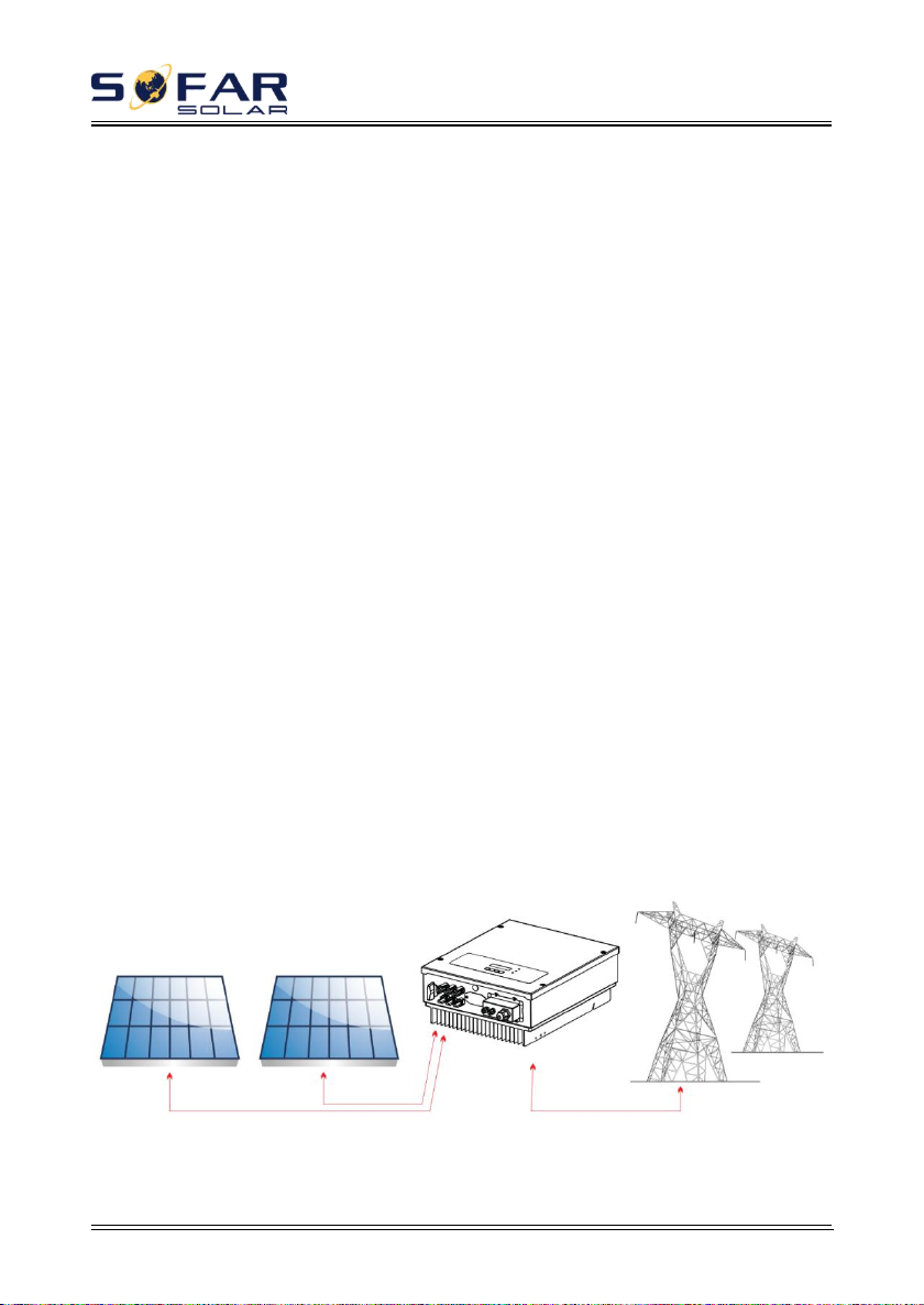
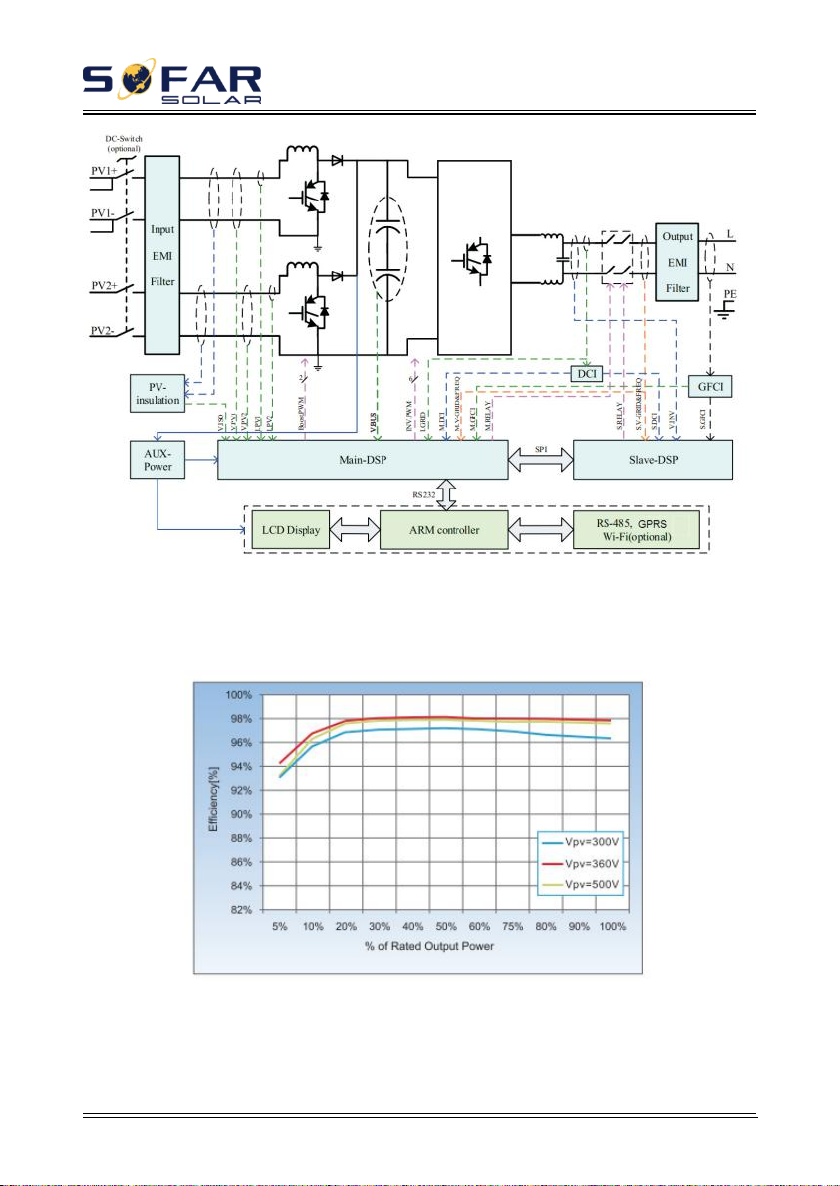
2.2. Function description............................................................................................- 8 -
2.3. Efficiency curve................................................................................................ - 10 -
3. Installation...................................................................................................................... - 11 -
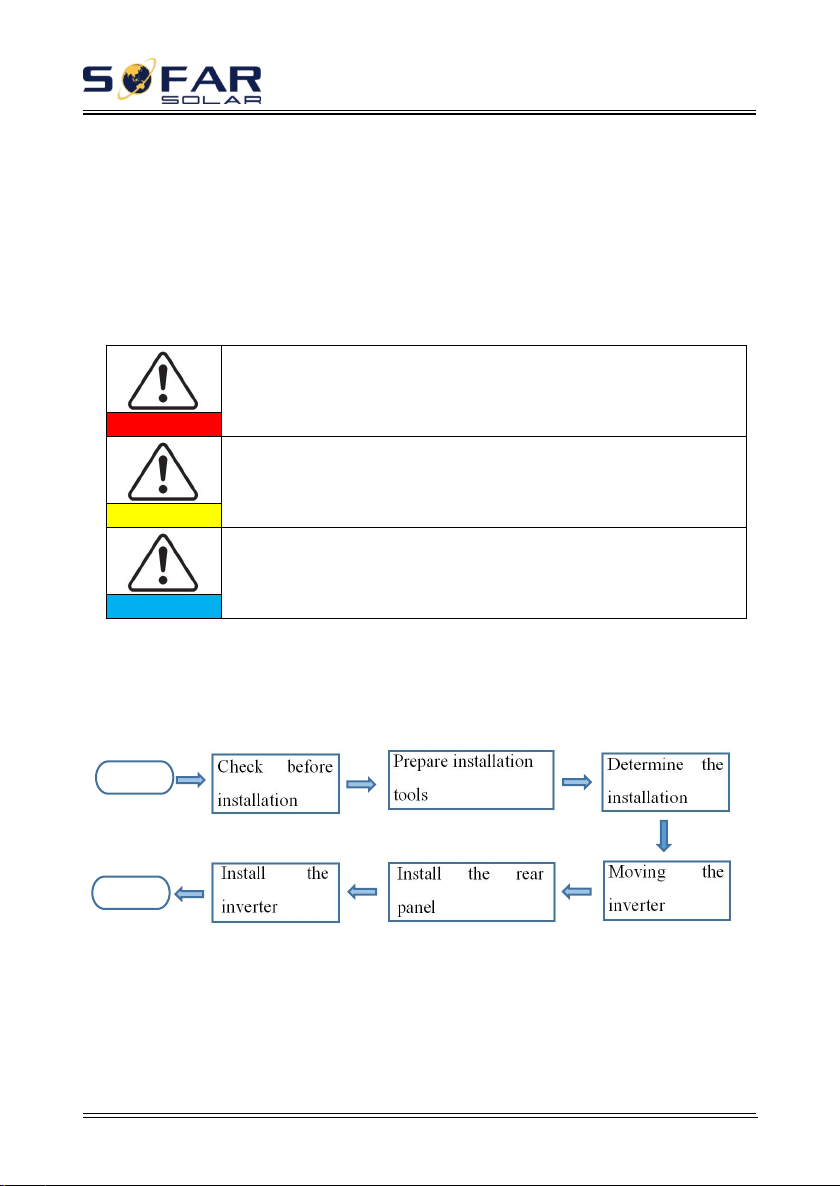
3.1. Installation Process............................................................................................- 11 -
3.2. Checking Before Installation.............................................................................- 11 -
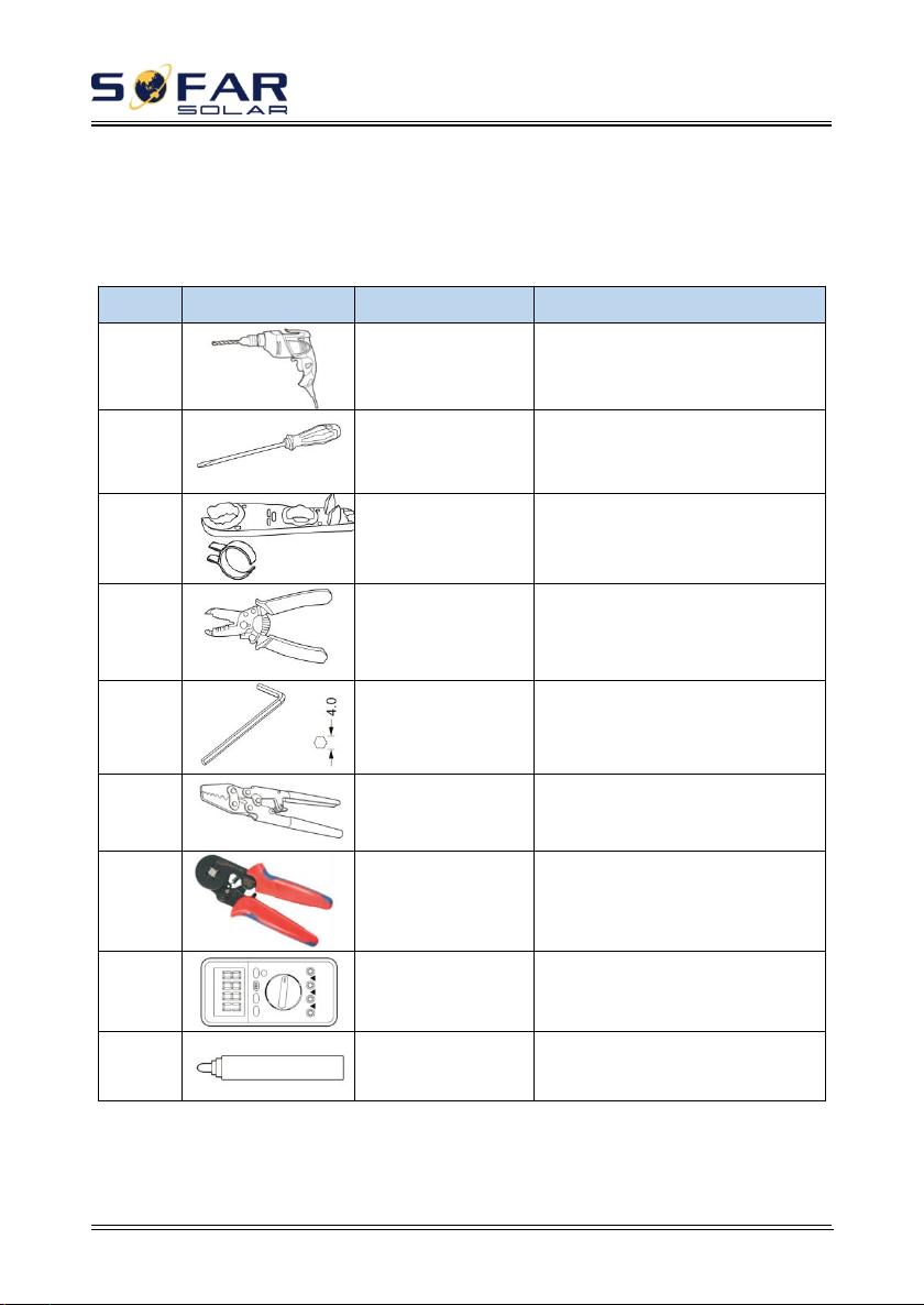
3.3. Tools..................................................................................................................- 14 -
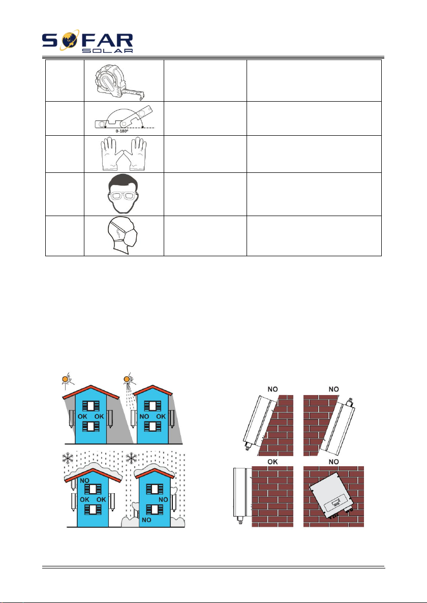
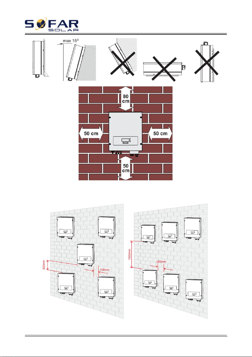
3.4. Determining the Installation Position............................................................... - 15 -
3.5. Moving the SOFAR 7.5KTLM......................................................................... - 17 -
3.6. Installing SOFAR 7.5KTLM.............................................................................- 18 -
4. Electrical Connections.................................................................................................... - 20 -
4.1. Electrical connection.........................................................................................- 21 -
4.2. Connecting PGND Cables................................................................................ - 21 -
4.3. Connecting DC Input Power Cables................................................................. - 23 -
4.4. Connecting AC Output Power Cables...............................................................- 26 -
4.5. RS485,CT,inverter logic interface connection.................................................. - 29 -
4.6. WIFI/GPRS module installation procedure...................................................... - 34 -
4.7. Communication method....................................................................................- 35 -
5. Commissioning of inverter............................................................................................. - 39 -
5.1. Safety inspection before commissioning.......................................................... - 39 -
5.2. Start inverter......................................................................................................- 39 -
6. Operation interface......................................................................................................... - 40 -
6.1. Operation and Display Panel.............................................................................- 40 -
6.2. Standard Interface............................................................................................. - 41 -
6.3. Main Interface................................................................................................... - 44 -
6.4. Update Software online.....................................................................................- 48 -
7. Trouble shooting and maintenance................................................................................. - 50 -
7.1. Trouble shooting............................................................................................... - 50 -
7.2. Maintenance...................................................................................................... - 59 -
8. Technical data................................................................................................................. - 60 -
8.1. Input parameters (DC)...................................................................................... - 60 -
8.2. Output parameters (AC)....................................................................................- 61 -
8.3. Efficiency,Protection and Communication....................................................... - 62 -
8.4. General Date..................................................................................................... - 63 -
9. Quality Assurance........................................................................................................... - 64 -

SOFAR 7.5KTLM User manual
Copyright © Shenzhen SOFARSOLAR Co., Ltd
II
Notice
This manual contains important safety instructions that must be followed
during installation and maintenance of the equipment.
Save these instructions!
This manual must be considered as an integral part of the equipment. The
manual must always accompany the equipment,even when it is transferred to
another user or field.
Copyright Declaration
The copyright of this manual belongs to Shenzhen SOFARSOLAR
Co.,Ltd.Any corporation or individual should not plagiarize, partially copy or fully
copy it (including software, ect .),and no reproduction or distribution of it in any
form or by any means.All right reserved.
SOFARSOLAR reserves the right of final interpretation.This manual is
subject to change according to user’s or customer’s feedback.Please check our
website at http://www.sofarsolar.com for latest version.

SOFAR 7.5KTLM User manual
Copyright © Shenzhen SOFARSOLAR Co., Ltd
III
Preface
Outline
Please read the product manual carefully before installation,operation or
maintenance.This manual contains important safety instructions and installation
instructions that must be followed during installation and maintenance of the
equipment.
Scope
This product manual describes the installation,electrical connections,
commissioning,maintenance and troubleshooting of SOFAR 7.5KTLM inverters
Keep this manual where it will be accessible at all times.
Target Group
This manual is intended for qualified electrical technical personnel who are
responsible for inverter installation and commissioning in the PV power system and
PV plant operator.
Symbols Used
This manual is provides safety operation information and uses the symbol in
order to ensure personal and property security and property security and use
inverter efficiently when operating the inverter. You must understand these
emphasized information to avoid the personal injury and property loss.Please read
the following symbols used in this manual carefully.

SOFAR 7.5KTLM User manual
Copyright © Shenzhen SOFARSOLAR Co., Ltd
IV
Danger indicates a hazardous situation which, if not
avoided, will result in death or serious injury.
Danger
Warning indicates a hazardous situation which, if not
avoided, could result in death or serious injury.
Warning
Caution indicates a hazardous situation which, if not
avoided, could result in minor or moderate injury.
Caution
Attention indicates potential risks which, if not
avoided, may lead to equipment fault or property damage.
Attention
Note provides tips that are valuable for the optimal
operation of the product.
Note

SOFAR 7.5KTLM User manual
Copyright © Shenzhen SOFARSOLAR Co., Ltd
- 1 -
1. Basic safety information
If you have any question or problem when you read the following
information, please contact Shenzhen SOFARSOLAR Co., Ltd.
Note
Outlines of this chapter
Safety instruction
It mainly introduce the safety instruction when install and operate the
equipment.
Symbols and signs
It mainly introduce the safety symbols on the inverter.
1.1. Safety instructions
Read and understand the instructions of this manual, and be familiar with
relevant safety symbols in this chapter, then start to install and troubleshoot the
equipment.
According to the national and state requirements, before connecting to the
electrical grid, you must get permission from the local electrical grid operation can
only be performed by qualified electrical engineer.
Please contact the nearest authorized service center if any maintenance or
repair is needed.Contact your distributor for the information of the nearest
authorized service center. Do NOT repair it by yourself, it may cause injury or
property damage.
Before installing and maintaining the equipment, you should turn the DC
switch OFF to cut off the high voltage DC of the PV array. You can also turn the
switch in the PV combiner box OFF to cut off the high voltage DC. Otherwise,
serious injury may be caused.

SOFAR 7.5KTLM User manual
Copyright © Shenzhen SOFARSOLAR Co., Ltd
- 2 -
Qualified persons
The customer must make sure the operator has the necessary skill and training
to do his/her job.Staff in charge of using and maintaining the equipment must be
skilled,aware and mature for the described tasks and must have the reliability to
correctly interpret what is described in the manual. For safety reason only a
qualified electrician, who has received training and / or has demonstrated skills and
knowledge in construction and in operation of this unit, can install this inverter.
Shenzhen SOFARSOLAR Co., Ltd does not take any responsibility for the property
destruction and personal injury because of any incorrect use.
Installation requirements
Please install inverter according to the following section. Fix the inverter on
an appropriate objects with enough load bearing capacity (such as walls, PV racks
etc.), and ensure that inverter is vertical placed. Choose a place suitable for
installing electrical devices. And assure there is enough fire exit space, convenient
for maintenance. Maintain proper ventilation to ensure enough air cycle to cool the
inverter.
Transport requirements
If you find packing problems that may cause the damage of the inverter, or
find any visible damage, please immediately notice the responsible transportation
company. You can ask solar equipment installation contractor or Shenzhen

SOFAR 7.5KTLM User manual
Copyright © Shenzhen SOFARSOLAR Co., Ltd
- 3 -
SOFARSOLAR Co.Ltd for help if necessary.
Transport of the equipment, especially by road, must be carried out with by suitable
ways and means for protecting the components (in particular, the electronic
components) from violent shocks, humidity, vibration, etc.
Electric connection
Please comply with all the current electrical regulations about accident
prevention in dealing with the solar invert.
Before the electrical connection, make sure to use opaque
material to cover the PV modules or to disconnect PV array DC
switch. Exposure to the sun, PV array will produce a dangerous
voltage!
Danger
All installation accomplished only by professional electrical
engineer!
Must be trained;
Completely read the manual operation and understand
relevant matter.
Warning
Get permission from the local electrical gird operator,
complete all electrical connections by professional electrical
engineer, then connect inverter to electrical grid.
Attention
It’s forbidden to remove the tamper evident label, or open the
inverter. Otherwise Sofarsolar will not provide warranty or
maintenance!
Note
Operation
Touching the electrical grid or the terminal of the equipment
may lead to electrocution or fire!
Don’t touch the terminal or conductor connected to the
electrical grid.
Pay attention to any instructions or safety documents related to
grid connection.
Danger
Some internal components will be very hot when inverter is
working. Please wear protective gloves!
Attention
Maintenance and repair

SOFAR 7.5KTLM User manual
Copyright © Shenzhen SOFARSOLAR Co., Ltd
- 4 -
Before any repair work, turn OFF the AC circuit breaker
between the inverter and electrical grid first, then turn OFF the DC
switch.
After turning OFF the AC circuit breaker and DC switch, wait
for 5 minutes at least before carrying out any maintenance or repair
work.
Danger
Inverter should work again after removing any faults. If you
need any repair work, please contact with the local authorized
service center.
Can’t open the internal components of inverter without
authorized. Shenzhen SOFARSOLAR Co., Ltd. does not take any
responsibility for the losses from that.
Attention
EMC / noise level of inverter
Electromagnetic compatibility (EMC) refers to that one electrical equipment
functions in a given electromagnetic environment without any trouble or error, and
impose no unacceptable effect upon the environment. Therefore, EMC represents
the quality characters of an electrical equipment.
The inherent noise-immune character: immunity to internal electrical noise.
External noise immunity: immunity to electromagnetic noise of external system.
Noise emission level: influence of electromagnetic emission upon environment.
Electromagnetic radiation from inverter may be harmful to
health!
Please do not continue to stay around the inverter in less than 20
cm when inverter is working.
Danger
1.2. Symbols and signs
Caution of burn injuries due to hot enclosure!
You can only touch the screen and pressing key of the inverter
while it’s working.
Caution
PV array should be grounded in accordance to the requirements
of the local electrical grid operator!
We suggest that all PV module frames and inverter are reliably
grounded to protect the PV system and personnel security.
Attention
Ensure input DC voltage < Max. DC voltage .Over voltage may
cause permanent damage to inverter or other losses, which will not
be included in warranty!
Warning

SOFAR 7.5KTLM User manual
Copyright © Shenzhen SOFARSOLAR Co., Ltd
- 5 -
Signs on the inverter
There are some symbols which are related to security on the inverter. Please
read and understand the content of the symbols, and then start the installation.
There is a residual voltage in the inverter! Before opening the
equipment, operator should wait for five minutes to ensure the
capacitor is discharged completely.
Caution, risk of electric shock.
Caution hot surface.
Comply with the Conformite Europeenne (CE) certification.
Grounding point.
Please read this manul before install SOFAR 7.5KTLM.
This indicates the degree of protection of the equipment
according to IEC standard 70-1 (EN 60529 June 1997).
Positive pole and negative pole of the input voltage (DC).

SOFAR 7.5KTLM User manual
Copyright © Shenzhen SOFARSOLAR Co., Ltd
- 6 -
2. Product characteristics
Outlines of this chapter
Product dimensions
It introduces the field of use, and the overall dimensions of SOFAR 7.5KTLM
inverters.
Function description
It introduces how SOFAR 7.5KTLM inverters work and the function modules
inside.
Efficiency curves
It introduces the efficiency curves of in the inverter.
2.1. Product dimensions
SOFAR 7.5KTLM is a dual MPPT grid-tied PV inverter which converts the
DC power generated by PV arrays into sine wave single-phase AC power and feeds
it to the public electrical grid, AC circuit breaker (refer to Section 4.4) and DC
switch used as disconnect device, and the disconnect device shall be easily
accessible.
Figure2-1 PV Grid-tied System
SOFAR 7.5KTLM inverters can only be used with photovoltaic modules that

SOFAR 7.5KTLM User manual
Copyright © Shenzhen SOFARSOLAR Co., Ltd
- 7 -
do not require one of the poles to be grounded. The operating current during normal
operation must not exceed the limits specified in the technical specifications. Only
the photovoltaic modules can be connected to the input of the inverter (do not
connect batteries or other sources of power supply).
The choice of optional parts of inverter should be made by a qualified
technician who knows the installation conditions clearly.
Overall dimensions: L×W×H=467mm×352mm×157mm
Figure 2-2 Front view and left view dimensions
Figure 2-3 Back view and Bracket dimensions

SOFAR 7.5KTLM User manual
Copyright © Shenzhen SOFARSOLAR Co., Ltd
- 8 -
Figure 2-4 Bracket dimensions of SOFAR7.5KTLM
Labels on the equipment
2.2. Function description
DC power generated by PV array is filtered through Input Board before
entering into Power Board. Input Board also offer functions such as insulation
impedance detection and input DC voltage / current detection. DC power is
converted to AC power by Power Board. AC power is filtered through Output
Board then AC power is fed into the grid. Output Board also offer functions such as
grid voltage / output current detection, GFCI and output isolation relay. Control
Board provides the auxiliary power, controls the operation state of inverter and
The labels must
NOT be hidden with
objects and extraneous parts
(rags,boxes,equipment,etc.);they
must be cleaned regularly and
kept visible at all times.

SOFAR 7.5KTLM User manual
Copyright © Shenzhen SOFARSOLAR Co., Ltd
- 9 -
shows the operation status by Display Board. Display Board displays fault code
when inverter is in abnormal operation conditions. At the same time, Control Board
can trigger the relay so as to protect the internal components.
Function module
A. Energy management unit
This control can be used to switch the inverter on/off through an external
(remote) control.
B. Feeding reactive power into the grid
The inverter is able to produce reactive power and can therefore feed it into
the grid through the setting of the phase shift factor. Feed-in management can be
controlled directly by the grid company through a dedicated RS485 serial interface.
C. Limiting the active power fed into the grid
The inverter, if enabled can limit the amount of active power fed into the grid
by the inverter to the desired value (Expressed as a percentage).
D. Self power reduction when grid is over frequency
When the grid frequency is higher than the limited value, inverter will reduce
output power which is necessary for the grid stability.
E. Data transmission
The inverter or a group of inverters may be monitored remotely through an
advanced communication system based on RS-485 serial interface, or remotely via
the WIFI.
F. Software update
SD card is used for updating the firmware.
Electrical block diagram
Figure2-5 Electrical block diagram

SOFAR 7.5KTLM User manual
Copyright © Shenzhen SOFARSOLAR Co., Ltd
- 10 -
2.3. Efficiency curve

SOFAR 7.5KTLM User manual
Copyright © Shenzhen SOFARSOLAR Co., Ltd
- 11 -
3. Installation
Outlines of this chapter
This topic describes how to install the SOFAR 7.5KTLM .
Installation notes
3.1. Installation Process
Figure3-1 Installation flowchart
3.2. Checking Before Installation
Checking Outer Packing Materials
Do NOT install the SOFAR 7.5KTLM on flammable material.
Do NOT install the SOFAR 7.5KTLM in an area used to store
Flammable or explosive material.
Danger
The enclosure and heat sink are very hot while the inverter is
working, therefore do NOT install the SOFAR 7.5KTLM in places
where you might touch them inadvertently.
Caution
Consider the weight of SOFAR 7.5KTLM when transporting
and moving the inverters.
Choose an appropriate mounting position and surface.
Assign at least two persons to install the inverter.
Attention
Start
Check before
installation
Prepare installation
tools
Determine the
installation
Moving the
inverter
Install the rear
panel
Install the
inverter
End

SOFAR 7.5KTLM User manual
Copyright © Shenzhen SOFARSOLAR Co., Ltd
- 12 -
Packing materials and components may be damaged during transportation.
Therefore, check the outer packing materials before installing the inverter. Check
the outer packing materials for damage, such as holes and cracks. If any damage is
found, do not unpack the SOFAR 7.5KTLM and contact the dealer as soon as
possible. You are advised to remove the packing materials within 24 hours before
installing the SOFAR 7.5KTLM inverter.
Checking Deliverables
After unpacking the inverter, check whether deliverables are intact and
complete. If any damage is found or any component is missing, contact the dealer.
Table3-1 shows the components and mechanical parts that should be delivered.
NO.
Picture
Description
Quantity
1
7.5KTLM
1pcs
2
Rear panel
1pcs
3
PV+ input terminal
3pcs
4
PV- input terminal
3pcs
5
Metal terminals secured
to PV+ input power cables
3pcs
6
Metal terminals secured
to PV- input power cables
3pcs

SOFAR 7.5KTLM User manual
Copyright © Shenzhen SOFARSOLAR Co., Ltd
- 13 -
7
M5Hexagon screws
2pcs
8
Expansion bolts
10pcs
9
M6 flat washer
10pcs
10
Self-tapping screw
8pcs
11
Tubular pressure terminal
3pcs
12
Manual
1pcs
13
The warranty card
1pcs
14
Registration Form
1pcs
15
485 terminal (2pin)
1pcs

SOFAR 7.5KTLM User manual
Copyright © Shenzhen SOFARSOLAR Co., Ltd
- 14 -
3.3. Tools
Prepare tools required for installation and electrical connections.
Table 3-2 shows the tools required for installation and electrical connections.
NO.
Tool
Model
Function
1
Hammer drill
Recommend drill
dia. 6mm
Used to drill holes on the wall.
2
Screwdriver
wiring
3
Removal tool
Remove PV termin
4
Wire stripper
Strip wire
5
4mm Allen
Wrench
Turn the screw to connect rear
panel with inverter.
6
Crimping tool
Used to crimp power cables
7
Wire crimpers
Crimp tubular pressure terminal
8
Multi-meter
Used to check grounding
9
Marker
Used to mark signs

SOFAR 7.5KTLM User manual
Copyright © Shenzhen SOFARSOLAR Co., Ltd
- 15 -
10
Measuring tape
Used to measure distances
11
Level
Used to ensure that the rear panel
is properly installed
12
ESD gloves
Operators wear
13
Safety goggles
Operators wear
14
Anti-dust respirator
Operators wear
3.4. Determining the Installation Position
Determine an appropriate position for installing the SOFAR 7.5KTLM inverter.
Comply with the following requirements when determining the installation
position:
Figure3-2 Installation Requirements

SOFAR 7.5KTLM User manual
Copyright © Shenzhen SOFARSOLAR Co., Ltd
- 16 -
clearance for single SOFAR 7.5KTLM Inverter
Installation of multiple SOFAR 7.5KTLM inverter
Table of contents
Other Sofar Inverter manuals

Sofar
Sofar 255KTL-HV-TRO User manual

Sofar
Sofar SOFAR 3K-6KTLM-G2 User manual

Sofar
Sofar 125KTLX-G4 User manual

Sofar
Sofar DRM0 Reference manual

Sofar
Sofar 3K-6KTLM User manual

Sofar
Sofar HYD 6000-EP User manual

Sofar
Sofar HYD 3 6K-EP Series User manual

Sofar
Sofar 25KTLX-G3 User manual

Sofar
Sofar HYD 5KTL-3PH User manual

Sofar
Sofar HYD3000-ES User manual

Sofar
Sofar 100KTLX-G4 User manual

Sofar
Sofar CXAU0655BVS User manual

Sofar
Sofar 250KTL-HV User manual

Sofar
Sofar 60KTLX-G3 User manual

Sofar
Sofar 255KTL-HV User manual

Sofar
Sofar SOFAR 3K-6KTLM-G2 User manual

Sofar
Sofar 3KTLM-G2 User manual

Sofar
Sofar ME 5KTL-3PH User manual

Sofar
Sofar 100KTLX-G4 User manual

Sofar
Sofar 100KTLX-G4 User manual