BEKA BA307SE User manual

Issue: 4
26th September 2023
BA307SE & BA327SE
Ex ec & Ex tc
loop-powered
pa el mou ti g i dicators
Issue 4

2
1. Descriptio
2. Operatio
2.1 Controls
3. Certificatio
3.1 IECEx, ATEX & UKEX Ex ec
gas certification.
3.2 Increased safety protection
3.3 ones, gas groups & T rating
3.4 4/20mA input
3.5 Special conditions for safe use
3.6 Certification label information
4. System Desig for Zo e 2 Gas
Hazardous Areas.
4.1 Transmitter loops
4.2 Remote indication
5. I stallatio
5.1 Location
5.2 Installation procedure
5.3 Indicator earthing
5.4 EMC
5.5 Scale card
6. Co figuratio a d Calibratio
6.1 Summary of configuration
functions.
6.2 Indicator function
6.3 Resolution
6.4 Position of decimal point
6.5 Calibration using an external
current source.
6.6 Calibration using internal reference.
6.7 Bargraph format and calibration
6.8 Function of the P push button
6.9 Tare function
6.10 Security code
6.11 Reset to factory defaults
6.12 Under and over-range
7. Li eariser
7.1 Lineariser calibration using an external
current source.
7.2 Lineariser calibration using internal
reference.
7.3 Lineariser error message
7.4 Under and over-range
7.5 Lineariser default configuration
8. Mai te a ce
8.1 Fault finding during commissioning
8.2 Fault finding after commissioning
8.3 Servicing
8.4 Routine maintenance
8.5 Guarantee
8.6 Customer comments
9. Accessories
9.1 Scale card
9.2 Tag information
9.3 Stainless steel support plate
9.4 Alarms
9.4.1 Solid state output
9.4.2 Ex ec certification
9.4.3 Configuration and adjustment.
9.4.4 Alarm enable
9.4.5 Setpoint adjustment
9.4.6 Alarm function
9.4.7 Alarm output status
9.4.8 Hysteresis
9.4.9 Alarm delay
9.4.10 Alarm silence time
9.4.11 Flash display when alarm occurs.
9.4.12 Access setpoint in display mode.
9.4.13 Adjusting alarm setpoint from
the display mode.
9.4.14 Displaying setpoints on
BA327SE bargraph.
9.5 Display backlight
9.5.1 Loop powering the backlight
9.5.2 Separately powering the backlight.
Appe dix 1 Use in an Ex p pressurised enclosure
Appe dix 2 IECEx, ATEX and UKEX dust
certification.
Appe dix 3 ETL & cETL certification for
installations in USA and Canada.
CONTENTS
The BA307SE & BA327SE pa el mou ti g i dicators are CE marked to show complia ce with the European Explosive Atmospheres Directive
2014/34/EU a d the European EMC Directive 2014/30/EU.
The i dicators are also UKCA marked to show complia ce with UK statutory requireme ts Equipment and rotective Systems Intended for
Use in otentially Explosive Atmospheres Regulations UKSI 2016:1107 (as amended)
a d with the Electromagnetic Compatibility Regulations UKSI 2016:1091 (as amended).

3
1. DESCRIPTION
These panel mounting, Ex ec increased safety
digital indicators display the current flowing in a
4/20mA loop in engineering units. They are loop
powered but only introduce a 1.2V drop, which
allows them to be installed into almost any 4/20mA
current loop. No additional power supply or battery
is required.
The two models are electrically similar, but have
different displays.
Model Display
BA307SE 4 digits 15mm high
BA327SE 5 digits 12.7mm high
and 31 segment bargraph.
This instruction manual supplements the
instruction sheet supplied with each instrument.
The main application of both models is to display a
measured variable or control signal in a one 2
gas hazardous area or a one 22 dust hazardous
process area. The zero and span of the display
are independently adjustable so that the indicator
can be calibrated to display any variable
represented by the 4/20mA current, e.g.
temperature, flow, pressure or level.
Optional factory fitted dual alarms and a green
display backlight which can be loop or separately
powered, should be specified when the instrument
is ordered.
Both models have been issued with an IECEx
Certificate of Conformity, and with ATEX and UKEX
Type Examination Certificates. These confirm that
both indicators comply with the requirements for
increased safety Ex ec protection, and with those
for dust ignition protection by enclosure Ex tc.
All the certificate numbers have an 'X' suffix
indicating that the two indicators are subject to
special condition for safe use. For installations in
one 2 the panel enclosure into which the
indicators are mounted must comply with Ex e
requirements which are defined in EN 60079-7.
The indicators may also be installed in an Ex p
panel enclosure as described in Appendix 1.
Installation requirements for use in one 22 dust
hazardous areas are described in Appendix 2.
Both indicators also have ETL and cETL
certification allowing installation in the USA and
Canada as described in Appendix 3.
2. OPERATION
Fig 1 shows a simplified block diagram of both
models. The 4/20mA input current flows through
resistor R1 and forward biased diode D1. The
voltage developed across D1, which is relatively
constant, is multiplied by a switch mode power
supply and used to power the instrument. The
voltage developed across R1, which is proportional
to the 4/20mA input current, provides the input
signal for the analogue to digital converter.
Each time a 4/20mA current is applied to the
instrument initialisation is performed during which
all segments of the display are activated, after five
seconds the instrument displays the input current
using the calibration information stored in the
instrument memory.
If the loop current is less than 1.2mA the indicator
will display the error message LPLo below this
input current the instrument will not function
correctly.
Fig 1 Indicator block diagram

4
2.1 Co trols
The indicators are controlled and calibrated via the
four front panel push button switches. In the
display mode i.e. when the indicator is displaying a
process variable, these push buttons have the
following functions:
(While this button is pushed the
indicator will display the input current in
mA, or as a percentage of the
instrument span depending upon how
the indicator has been configured.
When the button is released the normal
display in engineering units will return.
The function of this push button is
modified when optional alarms are
fitted to the indicator.
&While this button is pushed the
indicator will display the numerical
value and analogue bargraph* the
indicator has been calibrated to display
with a 4mAΦ input. When released the
normal display in engineering units will
return.
*While this button is pushed the
indicator will display the numerical
value and analogue bargraph* the
indicator has been calibrated to display
with a 20mAΦ input. When released
the normal display in engineering units
will return.
)No function in the display mode unless
the tare function is being used.
( + &Indicator displays firmware number
followed by version.
( + *Provides direct access to the alarm
setpoints when optional alarms are
fitted to the indicator and the ac5p
access setpoints in display mode
function has been enabled.
( + )Provides access to the configuration
menu via optional security code.
Notes: * BA327SE only
Φ If the indicator has been calibrated
using the CAL function, calibration
points may not be 4 and 20mA.
3. CERTIFICATION
Both models have IECEx, ATEX, UKEX, ETL &
cETL Ex ec increased safety gas certification and
Ex tc protection by enclosure dust certification.
The main sections of this instruction manual
describe IECEx, ATEX and UKEX gas certification.
Dust approval is described in Appendix 2 and
North American gas and dust certification in
Appendix 3.
3.1
IECEx, ATEX a d UKEX Ex ec gas certificatio
Testing and certification company Intertek Testing
& Certification Ltd have issued both indicators with
an IECEx Certificate of Conformity IECEx ITS
22.0023X, and a UKEX Type Examination
Certificate ITS22UKEX0609X. Similarly, testing
and certification company Intertek Italia S.p.A.
have issued both indicators with
an ATEX Type Examination Certificate
ITS-1 22ATEX34494X.
Both indicators carry the Community and UKCA
Marks, subject to local codes of practice, they may
be installed in any of the EEA member countries
and in the UK. The IECEx certificate allows
worldwide installation, either directly or as a means
to obtain local approval.
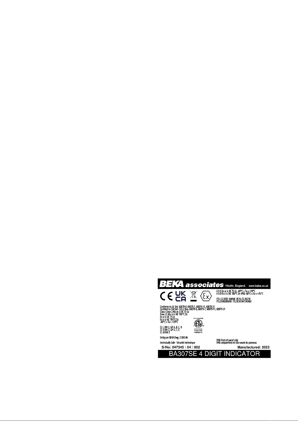
These instructions describe installations which
conform to EN 60079:14 Electrical installations
design, selection and erection. When designing
systems the local Code of Practice should always
be consulted. Fig 2 shows the certification
information label that is on the top of a BA307SE
indicator.
3.2 I creased safety protectio
Increased Safety Ex e protection applies additional
measures to provide increased security against the
possibility of excessive temperatures and against
the occurrence of arcs and sparks. The fifth edition
of international standard IEC 60079-7:2015
Equipment Protection by Increased Safety ‘e’
defines two levels of protection:
Ex eb EPL Gb
Equipment for installation in ones 1 or 2.
Ex ec EPL Gc
Equipment for installation in one 2.
Note: Ex ec supersedes Ex nA protection
following publication of the Ex n standard
EN IEC 60079-15:2019 which no longer
includes Ex nA protection.

5
3.3 Zo es, gas groups a d T rati g
The BA307SE and BA327SE indicators have been
certified as Group II Category 3G Ex ec ic IIC T5
Gc apparatus.
When connected to a suitable system and
correctly mounted in a panel enclosure:
The indicators may be installed in:
one 2 explosive gas air mixture not
likely to occur, and if it does
will only exist for a short time.
Be used with gases in groups:
Group A propane
Group B ethylene
Group C hydrogen
In gases that may safely be used with
equipment having a temperature classification
of:
T1 450oC
T2 300oC
T3 200oC
T4 135oC
T5 100oC
At ambient temperatures between -40 and
+70oC.
Note: When determining the maximum ambient
temperature, heat generating equipment mounted
in the same enclosure, or adjacent to the
enclosure, should be considered.
This allows both indicators to be used with most
common industrial gases except carbon disulphide
and ethyl nitrite which have an ignition temperature
of 95°C.
The Ex ic in the indicator's certification code refers
to the front panel push button contacts which are
non incendive and have been certified intrinsically
safe without the need for an external ener barrier
or galvanic isolator. This allows the indicators to
be adjusted when installed in one 2 or 22, but the
indicators themselves are not intrinsically safe and
should not be connected to an intrinsically safe
circuit.
3.4 4/20mA i put
The input safety parameters for the 4/20mA input,
terminals 1 and 3 are:
Umax = 30V dc
Imax = 200mA
The indicators are current input instruments
incorporating an internal protection circuit that
defines the voltage developed between the input
terminals 1 and 3.
3.5 Special co ditio s for safe use
All of the Ex ec certificates specify special
conditions for safe use and therefore have
certificate numbers with an 'X' suffix.
The certificates state that the BA307SE and
BA327SE indicators should be mounted such that
the rear of the indicator, including the terminals,
have additional protection. This protection should
comply with EN/IEC 60079-0 Clause 1 and provide
at least IP54 ingress protection as required by
IEC 60079-7.
Mounting the BA307SE or BA327SE in an Ex e
component certified enclosure satisfies these
requirements, but component certificates are only
intended to be used as part of a certified assembly.
Therefore the indicator certificate, the Ex e
enclosure certificate and the installation should be
be reviewed to ensure they are compatible.
3.6 Certificatio label i formatio
The certification information label is fitted in a
recess on the top of the instrument. It shows the
IECEx certification information, BEKA associates
name and location, year of manufacture and the
instrument serial number. ATEX, UKEX and North
American certification information is also shown.
Fig 2 BA307SE certification label

6
4. SYSTEM DESIGN FOR USE IN ZONE 2 GAS
HAZARDOUS AREAS.
4.1 Tra smitter loops
When correctly mounted in one 2 both indicators
may be connected in series with almost any
4/20mA current loop with apparatus in the safe
area, or with Ex e, Ex p or Ex d protected
apparatus located in ones 1 or 2. The indicators
are transparent to HART ® signals.
CAUTION
The BA307SE a d BA327SE are ot certified
i tri sically safe they should ot be
co ected to a i tri sically safe system.
ATTENTION
Les BA307SE et BA327SE e so t pas
certifiés sécurité i tri sèque, ils e doive t
pas être co ectés da s u système à
sécurité i tri sèque.
There are four design requirements:
1. The indicator must be installed in a panel
enclosure providing the additional rear
protection outlined in section 3.5 of this
manual. Installation in a certified Ex e
enclosure satisfies these requirements.
2. The Ex ec certificates specify that the
indicator should be powered from a limited
energy circuit having a maximum output
voltage of 30V dc. A low voltage instrument
supply, usually 24V, that complies with the
low voltage Directive and is CE/UKCA
marked, is usually considered acceptable.
3. Wiring should comply with Clause 9 of
EN 60079-14.
4. The loop must be able to tolerate the
additional 1.2V required to operate the
indicator. This increases to 5.0V if the
indicator is fitted with an optional backlight
which is loop powered. See 9.5.1.
Figs 2 illustrate a typical application in which a
BA307SE or BA327SE located in one 2 is
connected in series with a 2-wire Ex d transmitter
located in one 1. BEKA Application Guide
AG321, which can be downloaded from
www.beka.co.uk, contains examples of other Ex ec
indicator applications.
Fig 2 Typical one 2 transmitter loop
To comply with the requirements of
EN 60079:14 Electrical installations design,
selection and erection, each of the wires entering
the hazardous area should be individually fused
and contain a means of isolation. These two
requirements can be satisfied by using terminals
containing a fuse holder with an easily removable
fuse which can be extracted to achieve isolation as
shown in Fig 3.
This is a satisfactory method at the low voltages
and currents common in instrumentation systems.
Clear identification of, and easy access to the
means of isolation is essential for their effective
use. It is also necessary to ensure that the
maintenance procedure makes sure that
unauthorised replacement of the fuses does not
occur. It is not considered necessary to have a
means of isolation or electrical protection for the
screen.
For some applications Ex ec instrumentation
energised by a current limited power supply or
instrument that can be switched off, is considered
adequate and to comply with the requirements of
the standard.

7
Fig 3 Indicator installation in Ex e enclosure
with fuses in safe area terminals
4.2 Remote i dicatio
The BA307SE and the BA327SE may also be
driven directly from a safe area instrument with a
4/20mA output to provide a remote display within a
one 2 hazardous area.
There are four design requirements:
1. The indicator must be installed in a panel
enclosure providing the additional rear
protection outlined in section 3.5 of this
manual. Installation in a certified Ex e
enclosure satisfies these requirements.
2. The Ex ec certificates specify that the
indicator should be powered from a limited
energy circuit having a maximum output
voltage of 30V dc. This requirement is
satisfied if the 4/20mA indicator input current
is derived from an instrument powered by a
low voltage instrument supply, that complies
with the EU/EC Low voltage Directive is
usually acceptable..
3. Wiring should comply with Clause 9 of
BS EN 60079-14:2008.
4. The output from the safe area 4/20mA source
must be able to supply the 1.2V required to
operate the indicator. This increases to 5.0V
if the indicator includes an optional backlight
which is loop powered. See 9.5.1
.
A typical applications is shown in Fig 4
Fig 4 Remote indication in one 2 hazardous area
To comply with the requirements of
EN 60079:14 Electrical installations design,
selection and erection, each of the wires entering
the hazardous area should be individually fused
and contain a means of isolation. These two
requirements can be satisfied by using terminals
containing a fuse holder with an easily removable
fuse which can be extracted to achieve isolation.
This is a satisfactory method at the low voltages
and currents common in instrumentation systems.
Clear identification of, and easy access to the
means of isolation is essential for their effective
use. It is also necessary to ensure that the
maintenance procedure makes sure that
unauthorised replacement of the fuse(s) does not
occur. It is not considered necessary to have a
means of isolation or electrical protection for the
screen.
For some applications Ex ec instrumentation
energised by a current limited power supply or
instrument that can be switched off, is often
considered adequate and to comply with the
requirements of the standard.

8
5. INSTALLATION
5.1 Locatio
When installed in a panel enclosure complying with
the requirements for Ex e protection as specified in
section 3.5 of this manual, both indicators may be
located in a one 2 hazardous area providing that
the operating temperature is between –40°C and
+70°C and the installation complies with the
indicator's certification requirements.
The indicators may also be installed in an Ex p
panel enclosure located in one 2 as described in
Appendix 1.
Both indicators have a stainless steel Ex e
component certified housings which has 7J front of
panel impact resistance incorporating a 10mm
thick toughened glass window which can withstand
a 4J impact. This component Ex e certification
confirms that when a BA307SE or BA327SE
indicator is installed in an Ex e enclosure the
integrity of the enclosure and its Ex e component
certification is not compromised. The captive
silicone gasket provides an IP66 seal between the
indicator and the enclosure.
Although the front of the indicators have IP66
protection, they should be shielded from
continuous direct sunlight and severe weather
conditions.
Fig 5 show the overall dimensions of the indicators
together with the recommended panel enclosure
cut-out dimensions.
Fig 5 Dimensions
5.2 I stallatio Procedure
a. Cut the aperture specified in Fig 5 in the
panel enclosure. Ensure that the edges of
aperture are de-burred.
b. Inspect the indicator's captive gasket and
ensure that it is not damaged before inserting
the indicator into the panel enclosure
aperture as shown in Fig 7.
c. If the enclosure panel is less than 1.0mm
thick, or is non-metallic, an optional BEKA
stainless steel support plate should be slid
over the rear of the indicator before the panel
clamps are fitted to evenly distribute the
clamping force and prevent the enclosure
panel being distorted or creeping.
d. Slide a panel clamp into the two grooves at
each corner of the indicator housing with the
M3 stud protruding through the hole at the
rear of the clamp. Fit the stainless steel
spring washer over the stud and secure with
the stainless steel wing nut.
e. Evenly tighten the four clamps to secure the
instrument. The recommended minimum
tightening torque for each wing nut is 22cNm
(1.95 lbf in).
f. Connect the panel enclosure wiring to the
rear Ex e approved terminals. To fit a wire
into a terminal, insert an instrument
screwdriver into the slot at the side of the
wire entry and gently push the screwdriver
towards the entry as shown in Fig 6. This will
open the gripping spring and allow a wire to
be inserted into the terminal. When the
screwdriver is withdrawn the wire will be
secured. Only one wire should be inserted
into each terminal.
Fig 6 Inserting wire into rear terminals
Field wiring adjacent to the terminals should
be supported to prevent damage resulting
from vibration.
g. Finally, to prevent injury to technicians, fit a
silicone rubber push-on cap to the end of
each M3 threaded rod.

9
Fig 7 Installation procedure
5.3 I dicator earthi g
Both indicators have an M4 earth stud on the rear
panel which should be electrically connected to the
panel enclosure in which the indicator is mounted,
or to the plant equipotential conductor.
5.4 EMC
Both instruments comply with the requirements of
the European EMC Directive 2014/30/EU and the
UK Electromagnetic Compatibility Regulations
UKSI 2016:1091 (as amended). For specified
immunity all wiring should be in screened twisted
pairs, with the screens earthed in the safe area.
Fig 8 Rear terminals
5.5 Scale card
The indicator’s units of measurement can be
shown on a printed scale card in a window at the
right hand side of the display. The scale card is
mounted on a flexible strip that is inserted into a
slot at the rear of the instrument as shown in Fig 9.
Thus the scale card can easily be changed without
dismantling the indicator or removing it from the
Ex e panel or enclosure in which it is mounted.
New indicators are supplied with a printed scale
card showing the requested units of measurement,
if this information is not supplied when the indicator
is ordered a blank card will be fitted.
A pack of self-adhesive scale cards printed with
common units of measurement is available as an
accessory from BEKA associates. Custom printed
scale cards can also be supplied.
To change a scale card, unclip the protruding end
of the flexible strip by gently pushing it upwards
and pulling it out of the enclosure. Peel the
existing scale card from the flexible strip and
replace it with a new printed card, which should be
aligned as shown below. Do not fit a new scale
card on top of an existing card.
Align the self-adhesive printed
scale card onto the flexible strip
and insert the strip into the
indicator as shown below.
Install the new scale card by
gently pushing the flexible strip
into the slot at the rear of the
indicator, when it reaches the
internal end-stop secure it by
pushing the end of the flexible
strip downwards so that the
tapered section is held by the
rear panel of the indicator.
Fig 9 Inserting the flexible strip carrying the scale
card into the slot at the rear of indicator.

10

11
6. CONFIGURATION AND CALIBRATION
Indicators are configured and calibrated via the
four front panel push buttons. All the configuration
functions are contained in an easy to use intuitive
menu that is shown diagrammatically in Fig 10.
Each menu function is summarised in section 6.1
and includes a reference to more detailed
information. When the indicator is fitted with alarms
additional functions are added to the menu which
are described in section 9.3. Throughout this
manual push buttons are shown as (, ), & or
*, and legends displayed by the indicator are
shown 7 digit format as displayed by the indicators
e.g. CAL and alr2.
Access to the configuration menu is obtained by
operating the ( and ) push buttons
simultaneously. If the indicator security code is set
to the default 0000 the first parameter func will be
displayed. If a security code other than the default
code 0000 has already been entered, the indicator
will display CodE. Pressing the ( button will clear
this prompt allowing each digit of the code to be
entered using the * and & push buttons and the
( button to move control to the next digit. When
the correct four digit code has been entered
pressing ) will cause the first parameter func to
be displayed. If the code is incorrect, or a button
is not pressed within twenty seconds, the indicator
will automatically return to the display mode.
Once within the configuration menu the required
parameter can be reached by scrolling through the
menu using the * and &
push buttons as shown
in Fig 10. When returning to the display mode
following recalibration or a change to any function,
the indicator will display data followed by 5ave
while the new information is stored in non-volatile
memory.
All new indicators are supplied calibrated as
requested at the time of ordering. If calibration is
not requested, indicators will be supplied with the
following default configuration:
Default Co figuratio
BA307SE BA327SE
Access code code 0000 0000
Function func Linear Linear
Display at 4mA 2ero 0.0 0.00
Display at 20mA 5pan 100.0 100.00
Resolution re5n 1 digit 1 digit
Bargraph start barlo ----- 0.00
Bargraph finish barhi ----- 100.00
( button in display mode c-p % %
Tare tare Off Off
6.1 Summary of co figuratio fu ctio s
This section summarises each of the main
configuration functions and includes a cross
reference to a more detailed description. Fig 9
illustrates the location of each function within the
configuration menu. The lineariser and the
optional factory fitted alarms are described
separately in sections 7 and 9.4.3 of this manual.
Display Summary of fu ctio o
func I dicator fu ctio
Defines the relationship between the
4/20mA input current and the indicator
display. May be set to:
5td Standard linear relationship
root Square root extraction
lin 16 segment adjustable
lineariser – see section 7.
See section 6.2
re5n Display resolutio
Defines the resolution of the least
significant display digit. May be set to
1, 2, 5 or 10 digits.
See section 6.3
dp Decimal poi t
Positions a dummy decimal point
between any of the digits or turns it off.
See section 6.4
cal Calibratio of the digital display
usi g a exter al curre t source.
Enables the zero and span of the
indicator to be adjusted using an
external current source such as a
calibrator. When used with an accurate
traceable current source this is the
preferred method of calibration.
See section 6.5
5et Calibratio of display usi g i ter al
refere ces.
Enables the zero and span of the
indicator to be adjusted without the
need for an accurate input current or
disconnection from the 4/20mA loop.
See section 6.6
bar Bargraph format a d calibratio
Only the BA327SE has a bargraph.
The bargraph may be conditioned to
start from left, right or centre of the
display, or it may be disabled. When
optional alarms are fitted it can also
display both alarm setpoints and the
measured value. The bargraph may be
calibrated to start and finish at any
value within the indicator’s calibrated
digital display. See section 6.7

12
Display Summary of fu ctio o
c - - p Fu ctio of ( push butto
The indicator may be configured to
display the input current in milliamps, or
the input current as a percentage of the
4/20mA input when the ( push button
is operated in the display mode.
See section 6.8
tare Tare fu ctio
When enabled the tare function sets
the indicator display to zero when
the ) push button is operated in the
display mode.
See section 6.9
code Security code
Defines a four digit numeric code that
must be entered to gain access to the
configuration menu. Default code 0000
disables this security function and
allows unrestricted access to all
conditioning functions.
See section 6.10
r5et Reset
Contains two sub-functions, conf which
returns the indicator to the default
conditions shown in section 6.0 and
ltab which returns the lineariser to the
default conditions shown in section 7.5.
To prevent accidental use both resets
must be confirmed by entering 5ure
before they will be executed.
See section 6.11
6.2 I dicator fu ctio : func
This configuration function defines the relationship
between the indicator’s 4/20mA input current and
the indicator’s display. Three alternatives are
available:
5td Standard linear relationship
root Square root extraction
Lin 16 segment adjustable lineariser
To reveal the existing indicator function select func
from the configuration menu and press (. If the
function is set as required, press ) to return to
the menu, or press the * or & button to change
the setting, followed by the ) button to return to
the configuration menu.
5td Li ear
Provides a linear relationship between the
4/20mA indicator input current and the
indicator display.
root Square root extractio
Primarily intended to linearise the square
law 4/20mA output from differential
flowmeters.
For reference, the following table shows
the output current from a non-linearised
differential flowmeter.
% of full flow Curre t output mA
2.5 4.01
10.0 4.16
25.0 5.00
50.0 8.00
75.0 13.00
100.0 20.00
When the root function is selected the
indicator will display flow in linear units.
lin 16 segme t adjustable li eariser
Enables non linear variables to be
displayed by the indicator in linear
engineering units. Use of the lineariser is
described in section 7 of this instruction
manual.
6.3 Resolutio : re5n
This function defines the resolution of the least
significant display digit. Decreasing the display
resolution can improve the readability of a noisy
signal. Select re5n from the menu and press
( which will reveal the current display resolution.
To change the resolution press the * or &
button to select 1, 2, 5 or 10 digits, followed by the
) button to enter the selection and return to the
configuration menu.

13
6.4 Positio of the decimal poi t: dp
A dummy decimal point can be positioned between
any of the digits or it may be absent. To position
the decimal point select dP from the menu and
press (. The decimal point can be moved by
pressing the * or & push button. If a decimal
point is not required it should be positioned beyond
the most or least significant digit. When
positioned as required press the ) button to enter
the selection and return to the configuration menu.
6.5 Calibratio usi g a exter al
curre t source: cal
This function enables the zero and span of the
indicator to be adjusted using an external
calibrated current source. When used with an
accurate traceable current source this is the
preferred method of calibration.
ero is the indicator display with 4mA input
Span is the indicator display with 20mA input
To calibrate the indicator select cal from the
configuration menu and press (. The indicator
will display 2ero which is a request for a 4mA input
current. Adjust the external current calibrator to
4.000mA and again press ( which will reveal the
current zero display. The flashing digit of the
indicator display can be changed by pressing the
* or & buttons, when set as required pressing
( will transfer control to the next digit. When all
the digits have been adjusted, press ) to enter
the new zero and return to the 2ero prompt.
Pressing the * button will cause the indicator to
display 5pan which is a request for a 20mA input
current. Adjust the external current calibrator to
20.000mA and again press ( which will reveal
the existing span display. The flashing digit of the
indicator display can be changed by pressing the
* or & buttons, when set s required pressing (
will transfer control to the next digit. When all the
digits have been adjusted press ) to enter the
new span and return to the 5pan prompt. Finally
press ) again to return to the configuration menu.
Notes:
a. The indicator input current must be adjusted to
the required value before the zero and span
functions are entered by pressing the
( button.
b. Indicators may be calibrated at currents other
than 4 and 20mA, within the range 3.8 to
21.0mA providing the difference between the
two currents is greater than 4mA. If these
conditions are not complied with, the indicator
displays fail and aborts the calibration.
c. If the zero current is greater than the span
current the instrument will be reverse acting
i.e. an increasing input current will cause the
display to decrease.
6.6 Calibratio usi g i ter al refere ce: 5et
Using the 5et function the indicator can be
calibrated without the need to know the value of
the 4/20mA input current, or to disconnect the
indicator from the 4/20mA loop.
When using the 5et function the indicator’s internal
reference is used to simulate a 4mA and 20mA
input current.
ero is the display with a simulated 4mA input
Span is the display with a simulated 20mA input
To calibrate the indicator display select 5et from
the configuration menu and press (. The
indicator will display 2ero, pressing ( again will
reveal the current display at 4mA. The flashing
digit can be adjusted by pressing the * or &
buttons, when the flashing digit is correct pressing
( will transfer control to the next digit. When all
the digits have been adjusted, press ) to return
to the 2ero prompt.
To adjust the display at 20mA, press the * button
which will cause the indicator to display 5pan,
pressing ( will then reveal the indicator’s existing
display at 20mA. The flashing digit can be
adjusted by pressing the * or & buttons, when
the flashing digit is correct pressing ( will transfer
control to the next digit. When all the digits have
been adjusted press ) to return to the 5pan
prompt followed by ) to return to the 5et prompt
in the configuration menu.
6.7 Bargraph format a d calibratio : bar
Only the BA327SE has a bargraph
In addition to a five digit numerical display the
BA327SE has a 31 segment analogue bargraph
which may be configured to start and finish
anywhere within the indicator’s numerical display
range.
To configure the bargraph select bar from the
configuration menu and press (. The indicator
will display t pe, pressing ( again will reveal the
existing bargraph justification which can be
changed to one of the following four or five options
using the * or & button:
Bargraph justificatio starts from
left Left end of display
centr Centre of display
right Right end of display
alr5p Only with alarms – see section
9.4.14.
off Bargraph disabled
When set as required press ) to return to the
t pe sub-function prompt.

14
The indicator’s digital display at which the
bargraph starts is defined by the barlo sub-
function which is selected by pressing the *
button followed by the ( button which will reveal
the current indicator display at which the bargraph
starts. The flashing digit can be adjusted by
pressing the * or & buttons, when set as
required pressing ( will transfer control to the
next digit. When all the digits have been adjusted,
press ) to return to the barlo prompt from which
barhi which defines the finishing point of the
bargraph can be selected by pressing the *
button. barhi is adjusted in the same way as
barlo. When set as required, pressing ) twice
will return the display to the bar prompt in the
configuration menu.
Note: barlo must be set lower than barhi,
incorrect setting is indicated by the bargraph scale
flashing with a single bargraph segment activated.
6.8 Fu ctio of the ( push butto : c - - p
When the indicator is in the display mode,
operating the ( push button will display the input
current in milliamps, or the displayed value as a
percentage of the difference between the displayed
values at 4mA and 20mA inputs.
To check or change the function of the ( push
button select c - -p from the configuration menu
and press ( to reveal the current setting.
Pressing the * or & button will toggle the setting
between 4-20 the current display in milliamps and
pc the percentage display. When set as required
press ) to return to the c - - p prompt in the
configuration menu.
6.9 Tare fu ctio : tare
The tare function is primarily intended for use with
weighing system. When the indicator is in the
display mode and the tare function is activated,
pressing the ) button for more than three
seconds will zero the indicator display and activate
the tare annunciator. Subsequent operation of the
) push button for less than 3 seconds will return
the indicator to the gross display and deactivate
the tare annunciator.
To check or change the tare function select tare
from the configuration menu and press ( to
reveal the current setting. Pressing the * or &
button will toggle the setting between on and off.
When set as required press ) to return to the
tare prompt in the configuration menu.
6.10 Security code: code
Access to the instrument configuration menu may
be protected by a four digit security code which
must be entered to gain access. New instruments
are configured with the default security code 0000
which allows unrestricted access to all
configuration functions.
To enter a new security code select code from the
configuration menu and press ( which will cause
the indicator to display the existing security code
with one digit flashing. The flashing digit can be
adjusted using the * and & push buttons, when
set as required operating the ( button will
transfer control to the next digit. When all the
digits have been adjusted press ) to return to the
code prompt in the configuration menu. The
revised security code will be activated when the
indicator is returned to the display mode.
Please contact BEKA associates sales department
if the security code is lost.
6.11 Reset to factory defaults: r5et
This function enables the indicator and the
lineariser to be quickly returned to the factory
default configurations shown in sections 6.0 and
7.5
To reset the indicator or lineariser select r5et from
the configuration menu and press (, the indicator
will display one of the reset options conf or ltab.
conf Resets the indicator only to defaults
ltab Resets the lineariser only to defaults
Using the * or & push button select the required
sub-function and press (. To prevent accidental
resetting the request must be confirmed by
entering 5ure. Using the * button set the first
flashing digit to 5 and press ( to transfer control
to the second digit which should be set to u.
When 5urE has been entered pressing the )
button will reset the selected configuration menus
and return the display to the r5et function in the
configuration menu.
6.12 U der a d over-ra ge
If the numerical display range of the indicator is
exceeded, all the decimal points will flash as
shown below:
BA307SE BA327SE
Underrange -9.9.9.9 -9.9.9.9.9
Overrange 9.9.9.9 9.9.9.9.9
Although not guaranteed, most indicators will
continue to function normally with an input current
between 1.8mA and 4mA, at lower currents the
instrument will display lplo before it stops
functioning.
Under or overrange of the BA327SE bargraph is
indicated by an activated arrow at the appropriate
end of the bargraph and a flashing bargraph scale.

15
7. LINEARISER
A sixteen segment, seventeen breakpoint (0 to 16)
lineariser may be selected in the func section of
the configuration menu. The starting point and
slope of each straight line segment are fully
adjustable allowing the indicator to display most
non-linear process variables in linear engineering
units. Each break-point must occur at a current
greater than the preceding break-point and less
than the following break-point, in the range 3.8 to
21.0mA. If this requirement is not observed when
configuring the lineariser the indicator will display
fail and the configuration adjusted which
produced the error message will be ignored.
Fig 11 shows a typical linearised indicator
characteristic.
Fig 11 shows a typical linearising characteristic
Selecting lin in the func section of the
configuration menu activates the lineariser, this
does not change the configuration menu shown in
Fig 10, but the cal and 5et functions are extended
as shown in Fig 12. As with a linear indicator,
calibration of the lineariser may be performed with
an external current source using the cal function,
or with the internal reference using the 5et
function.
The lineariser calibration is retained irrespective of
how the indicator function func is subsequently
changed. It is therefore possible to select and
deselect the lineariser without having to
reconfigure it each time.
The lineariser calibration may be reset to the
factory default settings without changing the
indicator configure using the ltab function
described in section 6.11.
7.1 Li eariser calibratio usi g a exter al
curre t source.
This method allows direct calibration of the
lineariser with an external current source and is the
preferred method when traceability is required. If
the exact system non-linearity is unknown, this
method also allows direct calibration from the
variable to be displayed. e.g. the output from a
level sensor in an irregular tank may be displayed
in linear volumetric units by filling the tank with
known incremental volumes and calibrating the
indicator to display the sum of the increments at
each break-point.
The number of break-point required should first be
entered using the add and del functions. In both
these sub-functions the indicator initially displays
the current break-point and the total number of
break-points being used as shown below.
Display Descriptio of fu ctio
add Add a break-poi t
Adds a new break-point before the
displayed break-point. The calibration
of existing break-points is not changed,
but the identification number of all
subsequent break-points is increased
by one.
del Remove a break-poi t
Removes the displayed break-point and
joins the preceding break-point to the
following break-point with a straight
line. The identification number of all
subsequent break-points is decreased
by one.
To add a break-point use the * or & button to
select cal from the configuration menu and press
( which will result in the add sub-function prompt
being displayed. To enter the sub-function press
( which will reveal the current break-point and
the total number of break-points which have
already been entered. When adding a break-
point to a calibrated indicator, the insertion position
for the new segment can be selected using the *
or & push buttons. Each subsequent operation
of the ( push button will introduce an additional
break-point up to the maximum of n:16.

16

17
CAUTION
Whe addi g break-poi ts to a ew i dicator,
or followi g resetti g of the li eariser to the
factory defaults usi g the ltab fu ctio
described i sectio 6.11, ew break-poi ts
should be added betwee the two default
break-poi ts 0:1 a d 1:1. If ew break-poi ts
are added before breakpoi t 0:1 which has a
default setti g of 4mA, it will result i a fail
error message whe the i dicator display is
e tered.
ATTENTION
Lors de l'ajout de poi ts d'arrêt à u ouvel
i dicateur, ou après la réi itialisatio du
li éariseur aux valeurs d'usi e à l'aide de la
fo ctio ltab ,décrite da s la sectio 6.11, de
ouveaux poi ts d'arrêt doive t être ajoutés
e tre les deux valeurs par défaut poi ts
d'arrêt 0:1 et 1:1. Si de ouveaux poi ts d'arrêt
so t ajoutés ava t le poi t d'arrêt 0:1 do t le
réglage par défaut est de 4mA, il e résultera
u message d'erreur fail lorsque la valeur à
afficher est e trée.
The delete break-point sub-function del operates
in exactly the same way as the add sub-function
described above. Once within the del sub-
function each time the ( button is pressed a
break-point is removed. When deleting a break-
point from a calibrated indicator, the break-point to
be deleted can be selected using the * and &
push buttons. The minimum number of break-point
is 2, break-points 0:1 and 1:1.
When the required number of linearising break-
points has been entered, return to the linearisation
sub-menu by pressing ). The indicator will
display the add or del prompt depending upon the
last function used. Using the pt5 sub-function the
input current at which each break-point occurs and
the corresponding indicator display may now be
defined.
Using the * or * button select the pt5 function
in the sub-menu and press ( to enter the function
which will display the first break-point 0 : n, where n
is the total number of linearising break-points
entered – see Fig 12. The selected linearising
break-point can be changed using the * and &
buttons. When the required linearising break-point
has been selected set the indicator input current to
the exact value at which the break-point is required
and press (*. Using the * and & buttons and
the ( button to move between digits, enter the
required indicator display at this break-point.
When set as required, press the ) push button to
enter the required indicator display and return to
the sub-menu from which the next beak-point can
be selected.
* Note: The indicator input current must be
adjusted to the required value before the (
button is operated to enter the required indicator
display.
Error message
If duri g calibratio the i dicator displays a
fail error message the curre t at which the
selected break-poi t is bei g set is ot above
the proceedi g break-poi t or is ot below the
followi g break-poi t.
When all the break-points have been calibrated
pressing ) twice will return the indicator to the
cal function in the configuration menu.
7.2 Li eariser calibratio usi g the i ter al
refere ce.
The 5et function enables the lineariser to be
calibrated without the need for an accurate
external current source. Throughout the calibration
the indicator input current may be any value
between 4 and 20mA.
The 5et functions contains four sub-functions.
Display Descriptio of fu ctio
add Add a break-poi t
Adds a new break-point before the
displayed break-point. The calibration
of existing break-points is not changed,
but the identification number of all
subsequent break-point is increased by
one.
del Remove a break-poi t
Removes the displayed break-point
and joins the preceding segment to the
following segment with a straight line.
The identification number of all
subsequent break-points is decreased
by one.
in Defi es the curre t at which break-
poi t occurs.
Enables the required current at each
break-point to be defined without
having to input an accurate input
current to the indicator.
di5p Defi es i dicator display at break-
poi t.
Enables the indicator display at each
break-point to be defined.

18
The number of break-point required should first be
entered using the add and del sub-functions. In
both these sub-functions the indicator initially
displays the current break-point and the total
number of break-point being used as shown.
To add a break-point using the * or & button
select 5et from the configuration menu and press
( which will result in the add sub-function prompt
being displayed. To enter the sub-function press
( which will reveal the current break-point and
the total number of break-point which have already
been entered. Each subsequent operation of the
( push button will introduce an additional break-
point up to the maximum of n:16. When adding a
break-point to a calibrated indicator, the insertion
position for the new segment can be selected
using the * and & push buttons.
CAUTION
Whe addi g break-poi ts to a ew i dicator,
or followi g resetti g of the li eariser to the
factory defaults usi g the ltab fu ctio
described i sectio 6.11, ew break-poi ts
should be added betwee the two default
break-poi ts 0:1 a d 1:1. If ew break-poi ts
are added before breakpoi t 0:1 which has a
default setti g of 4mA, it will result i a fail
error message whe the i dicator display is
e tered.
ATTENTION
Lors de l'ajout de poi ts d'arrêt à u ouvel
i dicateur, ou après la réi itialisatio du
li éariseur aux valeurs d'usi e à l'aide de la
fo ctio ltab ,décrite da s la sectio 6.11, de
ouveaux poi ts d'arrêt doive t être ajoutés
e tre les deux valeurs par défaut poi ts
d'arrêt 0:1 et 1:1. Si de ouveaux poi ts d'arrêt
so t ajoutés ava t le poi t d'arrêt 0:1 do t le
réglage par défaut est de 4mA, il e résultera
u message d'erreur fail lorsque la valeur à
afficher est e trée.
The delete break-point, sub-function del operates
in exactly the same way as the add sub-function
described above. Once within the del function
each time the ( button is pressed a break-point is
removed. When deleting a break-point from a
calibrated indicator, the break-point to be deleted
can be selected using the & and * push
buttons. The minimum number of break-point is 2,
break-points 0:1 and 1:1.
When the required number of linearising break-
point has been entered, return to the linearisation
sub-menu by pressing ). The indicator will
display the add or del prompt depending upon the
last sub-function used. The indicator input current
and corresponding indicator display at each break-
point, which is the segment finishing point as
shown in Fig 11, can now be entered using the in
and di5p sub-functions.
Using the * or & button select in from the sub-
menu and press ( which will reveal the starting
point for the first segment 0:n, where n is the total
number of break-point entered. Press ( and use
the * and & buttons and the ( button to move
between digits, to enter the input current in
milliamps at which the first break-point is required,
usually 4.000mA. When set as required, press )
to return to the 0 : n prompt from which the next
break-point can be selected using the * and &
buttons. When the required break-point has been
selected press ( and set the indicator input
current at this break-point. Repeat this procedure
until the indicator input current at all the break-
points has been defined and then return to the in
sub-function by pressing the ) button.
The corresponding indicator display at each of the
break-points can now be defined using the di5p
sub-function Using the * and & buttons select
the di5p sub-function and press ( which will
reveal the starting point for the first break-point
0:n, where n is the total number of break-points
entered. Press ( and use the * and & buttons
and the ( button to move between digits, to enter
the required indicator display at the first break-
point. When set as required, press ) to return to
the 0 : n prompt from which the next break-point
can be selected using the * or & buttons.
When the required break-point has been selected
press ( and set the required indicator display at
this break-point.
Repeat this procedure until the indicator display at
all the break-points has been defined and then
return to the 5et function in the configuration menu
by pressing the ) button twice.
7.3 Li eariser error message
If an attempt is made to position a break-point at a
current which is not greater than the current of the
preceding break-point, or at a current which is not
less than the current of the following break-point,
the error message fail will be displayed. This
error message will also be displayed if an attempt
is made to position a break-point outside the
current range 3.8 to 21.0mA.

19
7.4 U der a d over-ra ge
The lineariser does not change the under and
over-range indication described in section 6.12. At
input currents below that specified for the first
break-point 0:n, the indicator will continue to use
the specified slope of the first segment. Although
not guaranteed, most indicators will continue to
function normally with an input current between
1.8mA and 4mA, at lower currents the instrument
will display lplo before it stops functioning.
At input currents above that specified for the last
break-point n:n, the indicator will continue to use
the slope specified for the last lineariser segment.
7.5 Li eariser default co figuratio
When the lineariser is reset to the factory defaults
using the ltab function described in section 6.11,
the defaults conditions are:
I dicator display
BA307SE BA327SE
First break-point 0:1 4mA 0.0 0.00
Second break-point 1:1 20mA 100.0 100.00

20
8. MAINTENANCE
8.1 Fault fi di g duri g commissio i g
If an indicator fails to function during
commissioning the following procedure should be
followed:
Symptom Cause Solutio
No display Incorrect wiring Check wiring
There should be
0.6 to 1.2V
between terminals
1 & 3 with terminal
1 positive.
With an optional
backlight which is
connected to be
loop powered,
there should be
3.4 to 5V between
terminals 3 & 12
with terminal 12
positive.
No display,
0V between
terminals 1 & 3.
Incorrect wiring
or no power
supply.
Check supply
voltage and
voltage drop
caused by all the
instruments in the
loop.
All decimal points
flashing.
Under-range if
–ve sign
displayed or
overrange.
Recalibrate the
indicator to reduce
the maximum
display.
Unstable display 4/20mA input is
noisy.
Reduce noise on
4/20mA input and/
or decrease
indicator
resolution.
Unable to enter
configuration
menu.
Incorrect
security code
entered.
Enter correct
security code, or
contact BEKA if
the code has been
lost.
8.2 Fault fi di g after commissio i g
The opening of an Ex ec enclosure for
maintenance purposes is not considered normal
operation (opening an Ex e certified enclosure in
which a BA307SE or BA327SE indicator is
mounted). However, Clause 4.8.1c of
BS EN 60079-17 Electrical installations inspection
and maintenance permits live maintenance in
one 2 or 22 if a risk analysis demonstrates that
this does not introduce an unacceptable risk and
can be performed without contaminating the
interior of the instrument with dust or moisture.
Some end-users may prefer not to permit live
maintenance to minimise risk.
ENSURE PLANT SAFETY BEFORE
STARTING MAINTENANCE
Live mai te a ce withi the Zo e 2
hazardous area should o ly be performed
whe it is permitted by risk a alysis or whe
there is o risk of a flammable atmosphere
bei g prese t.
S'ASSURER DE LA SECURITE DE
L'INSTALLATION AVANT DE COMMENCER LA
MAINTENANCE
La mai te a ce sous te sio à l'i térieur de
la zo e 2 e doit être effectuée que lorsqu'elle
est autorisée par l'a alyse des risques ou
lorsqu'il 'y a pas de risque de prése ce
d'u e atmosphère i flammable.
If an indicator fails after it has been functioning
correctly, follow the procedure shown in section
8.1. If this does not reveal the cause of the fault, it
is recommended that the instrument is replaced.
8.3 Servici g
All BA307SE and BA327SE loop powered
indicators are interchangeable if the required
optional backlight and alarms are fitted. A single
spare instrument may quickly be recalibrated to
replace any instrument that is damaged or fails.
No attempt should be made to repair instruments
at component level.
We recomme d that faulty i strume ts are
retur ed to BEKA associates or to your local
BEKA age t for repair.
Tous les indicateurs BA307SE et BA327SE
alimentés en boucle de courant sont
interchangeables si les options d'alarmes et le
rétroéclairage sont équipés. n instrument de
rechange peut être rapidement recalibré pour
remplacer un instrument endommagé ou
défaillant.Il ne faut pas essayer de réparer les
instruments au niveau composant.
Nous recommandons que les instruments
défectueux soient renvoyés à BEKA
associates ou l'agent local de BEKA pour
réparation.
This manual suits for next models
1
Table of contents
Other BEKA Measuring Instrument manuals