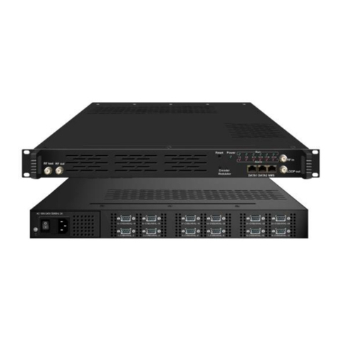
Softel SFT3316 User manual

SFT3316 16 in 1 IP QAM Modulator
User Manual
About This Manual
Intended Audience
This user manual has been written to help people who have to use, to integrate
and to install the product. Some chapters require some prerequisite knowledge in
electronics and especially in broadcast technologies and standards.
Disclaimer
No part of this document may be reproduced in any form without the written
permission of the copyright owner.
The contents of this document are subject to revision without notice due to

continued progress in methodology, design and manufacturing. SOFTEL shall
have no liability for any error or damage of any kind resulting from the use of this
document.
Copy Warning
This document includes some confidential information. Its usage is limited to the
owners of the product that it is relevant to. It cannot be copied, modified, or
translated in another language without prior written authorization from SOFTEL.
Directory
Chapter 1 Product Overview............................................................................................ 1
1.1 Outline...........................................................................................................................1
1.2 Inner Structure.............................................................................................................1
1.5 Specifications................................................................................................................ 2
Chapter 2 Physical Presentational Statement................................................................. 2
2.1 Front panel Illustration:..............................................................................................4
2.2 Rear panel Illustration:............................................................................................... 4
Chapter 3 Installation Guide............................................................................................ 5
3.1 Acquisition Check........................................................................................................ 5
3.2 Installation Preparation.............................................................................................. 5
Chapter 4 Web NMS Management.................................................................................. 8
4.1 Login..............................................................................................................................8
4.2 Operation...................................................................................................................... 8
Chapter 5 Troubleshooting............................................................................................. 22
Chapter 6 Packing list...................................................................................................23

SFT3316 16 in 1 IP QAM Modulator User Manual
1
Chapter 1 Product Overview
1.1 Outline
SFT3316 16 in 1 IP QAM modulator is the latest generational
Mux-scrambling-modulating all-in-one device developed by SOFTEL. It has 16
multiplexing channels, 16 scrambling channels and 16 QAM (DVB-C) modulating
channels, and supports maximum 512 IP input through the GE port and 16
non-adjacent carriers (50MHz~960MHz) output through the RF output interface.
The device is also characterized with high integrated level, high performance and
low cost. This is very adaptable to newly generation CATV broadcasting system.
1.2 Key Features
2 GE input, Data 1 and Data 2
Support up to 512 channels TS over UDP/RTP, unicast and multicast, IGMP v2\v3
Max 840Mbps for each GE input
Support accurate PCR adjusting
Support CA filtering ,PID remapping and PSI/SI editing
Supports up to 180 PIDS remapping per channel
Support DVB general scrambling system (ETR289), simulcrypt standards ETSI 101 197
and ETSI 103 197
Support 16 multiplexed or scrambled TS over UDP/RTP/RTSP output
16 non-adjacent QAM carriers output, compliant to DVB-C (EN 300 429) and ITU-T
J.83 A/B
Support RS (204,188) encoding
Support Web-based Network management
1.3 Inner Structure

SFT3316 16 in 1 IP QAM Modulator User Manual
2
1.4 Carrier Setting Illustration
1.5 Specifications
Input
Input
512 IP input, 2 100/1000M Ethernet Port(SFP
optional)
Transport Protocol
TS over UDP/RTP, unicast and multicast, IGMP
V2/V3
Transmission Rate
Max 840Mbps for each GE input
Mux
Input Channel
512
Output Channel
16
Max PIDs
180 per channel
Functions
PID remapping(auto/manually optional)
PCR accurate adjusting
PSI/SI table automatically generating
Scrambling
Parameters
Max simulscrypt CA
4
Scramble Standard
ETR289, ETSI 101 197, ETSI 103 197
Connection
Local/remote connection
Modulation
Parameters
DVB-C Modulator
Sectioon
J.83A
Constellation : 16/32/64/128/256QAM
Bandwidth :8M

SFT3316 16 in 1 IP QAM Modulator User Manual
3
J.83B
Constellation : 64QAM/ 256QAM
Bandwidth :6M
QAM Channel
16 non-adjacent carrier
Modulation Standard
EN300 429/ITU-T J.83A/B(DVB-C)
Symbol Rate
5.0~7.0Msps, 1ksps stepping
FEC
RS (204, 188)
RF Output
Interface
1 F typed output port for 16 carriers, 75Ω impedance
RF Range
50~960MHz, 1kHz stepping
Output Level
-20dBm~+10dBm(87~117dbµV), 0.1dB stepping
MER
≥ 40dB
TS output
16 IP output over UDP/RTP/RTSP, unicast/multicast, 2 100/1000M Ethernet
Ports
System
Network management software (NMS) supporting
General
Demission
420mm×440mm×44.5mm (WxLxH)
Temperature
0~45℃(operation), -20~80℃(storage)
Power Supply
AC 100V±10%, 50/60Hz or AC 220V±10%,
50/60Hz

SFT3316 16 in 1 IP QAM Modulator User Manual
4
Chapter 2 Physical Presentational Statement
2.1 Front panel Illustration:
2.2 Rear Panel Illustration:
1
NMS/CAS: network management port and CA data port
2
RF output port
3
Reset IP: Reset webmaster IP address, recover it to default IP address
4
Link/Act Indicators
5
Data Input/Output 1/2
6
Power switch
7
AC Power Socket
8
Grounding
3
4
5
6
7
8
1
2

SFT3316 16 in 1 IP QAM Modulator User Manual
5
Chapter 3 Installation Guide
3.1 Acquisition Check
When user opens the package of the device, it is necessary to check items according to packing
list. Normally it should include the following items:
SFT3316 16 in 1 IP QAM Modulator
User’s Manual
Power Cord
If any item is missing or mismatching with the list above, please contact local dealer.
3.2 Installation Preparation
When users install device, please follow the below steps. The details of installation will be
described at the rest part of this chapter. Users can also refer rear panel chart during the
installation.
The main steps of the installation include:
Checking the possible device missing or damage during the transportation
Preparing relevant environment for installation
Installing SFT3316 16 in 1 IP QAM Modulator
Connecting signal cables
Connecting communication port (if it is necessary)
3.2.1 Device’s Installation Flow Chart Illustrated as follows:
3.2.2 Environment Requirement

SFT3316 16 in 1 IP QAM Modulator User Manual
6
3.2.3 Grounding Requirement
All function modules’ good grounding is the basis of reliability and stability of devices.
Also, they are the most important guarantee of lightning arresting and interference
rejection. Therefore, the system must follow this rule.
Coaxial cables’ outer conductor and isolation layer should keep proper electric conducting
with the metal housing of device.
Item
Requirement
Machine Hall Space
When user installs machine frame array in one machine hall, the
distance between 2 rows of machine frames should be 1.2~1.5m and
the distance against wall should be no less than 0.8m.
Machine Hall Floor
Electric Isolation, Dust Free
Volume resistivity of ground anti-static material: 1X10⁷~1X10¹⁰ ,
Grounding current limiting resistance: 1M (Floor bearing should be
greater than 450Kg/㎡)
Environment
Temperature
5~40℃(sustainable ), 0~45℃(short time)
installing air-conditioning is recommended
Relative Humidity
20%~80% sustainable 10%~90% short time
Pressure
86~105KPa
Door & Window
Installing rubber strip for sealing door-gaps and dual level glasses
for window
Wall
It can be covered with wallpaper, or brightness less paint.
Fire Protection
Fire alarm system and extinguisher
Power
Requiring device power, air-conditioning power and lighting power
are independent to each other. Device power requires AC power
220V ±10% 50/60Hz or 110V ±10% 50/60Hz. Please carefully
check before running.

SFT3316 16 in 1 IP QAM Modulator User Manual
7
Grounding conductor must adopt copper conductor in order to reduce high frequency
impedance, and the grounding wire must be as thick and short as possible.
Users should make sure the 2 ends of grounding wire well electric conducted and be
antirust.
It is prohibited to use any other device as part of grounding electric circuit
The area of the conduction between grounding wire and device’s frame should be no less
than 25mm2.
3.2.4 Frame Grounding
All the machine frames should be connected with protective copper strip. The grounding wire
should be as short as possible and avoid circling. The area of the conduction between
grounding wire and grounding strip should be no less than 25mm2.
3.2.5 Device Grounding
Connecting the device’s grounding rod to frame’s grounding pole with copper wire.
3.3 Wire’s Connection
3.3.1 Power cord connection
The power socket is located on the right of rear panel, and the power switch is on the left of
front panel. User can plug one end of the power cord to the socket and insert the other end to
AC power. When the device solely connects to protective ground, it should adopt independent
way, say, share the same ground with other devices. When the device adopts united way, the
grounding resistance should be smaller than 1Ω.
Caution: Before connecting power cord to SFT3316 16 in 1 IP QAM Modulator, user should
set the power switch to “OFF”.
3.3.2 Signal and NMS Cable Connection
The signal connections include the connection of input signal cable and the connection of output
signal cable.

SFT3316 16 in 1 IP QAM Modulator User Manual
8
Chapter 4 Web NMS Management
User can only control and set the configuration in computer by connecting the device to web
NMS Port. User should ensure that the computer’s IP address is different from this device’s IP
address; otherwise, it would cause IP conflict.
4.1 Login
The factory default IP address please check the rear panel of the device (Usually
1.0.0.101/102/103), if no IP address on rear panel, the default IP address should be
192.168.0.136, and users can connect the device and web NMS through this IP address.
Connect the PC (Personal Computer) and the device with a net cable, and use ping command to
confirm they are on the same network segment. For instance, the PC IP address is
192.168.99.252, we then change the device IP to 192.168.99.xxx (xxx can be 0 to 255 except
252 to avoid IP conflict).
Launch the web browser an input the device IP address in the browser’s address bar and press
Enter.
It will display the Login interface as Figure-1. Input the Username and Password (Both the
default Username and Password are “admin”.) And then click “Login” to start the device setting.
Figure-1
4.2 Operation
4.2.1 Summary
When we confirm the login, it will display the summary interface as Figure-2 where users have an

SFT3316 16 in 1 IP QAM Modulator User Manual
9
over view of the system information.
Figure-2
4.2.2 Monitor
Monitor → Input Status:
Clicking “Input Status”, it will display the interface as Figure-3 where users can monitor the
input status of Data1 and Data 2.
User can click any item
here to enter the
corresponding interface
to check information or
set the parameters.

SFT3316 16 in 1 IP QAM Modulator User Manual
10
Figure-3
Monitor → Output Status:
Clicking “Output Status”, it will display the interface as Figure-4/5 where users can monitor
output status of the 16 IP and 16 QAM.
Figure-4

SFT3316 16 in 1 IP QAM Modulator User Manual
11
Figure-5
4.2.3 Parameters
Parameters → TS Config:
Clicking “TS Config”, it will display the interface where users can configure the output TS
parameters in this interface.
Output TS X
Clicking “Output TS X”, it will display the interface as Figure-6 where users can select the
output TS channels.

SFT3316 16 in 1 IP QAM Modulator User Manual
12
Figure-6
Stream Select
Clicking “Stream Select”, it will display the interface where users can choose the programs to
Mux out. (Figure-7)
Figure7
Configure ‘Input Area’ and ‘Output Area’ with buttons in ‘Operation Area’. Instructions are as
below:
To select output TS channel 1-16
Input Area
Output Area
Operation Area

SFT3316 16 in 1 IP QAM Modulator User Manual
13
: To add input channel which come from Data1and Data 2
: To edit the input channel
: To delete the input channel
: To delete all inputs channel
: To check input IP lock or not, green means current IP locked
: To check current TS overflow or not, red color means current TS overflow,
need reduce program
:Enable/disable the CA Filter function. Clicking the box, user can filter the input CA to
avoid disturbing with the device scrambling function.
: To enable/disable the PID remapping
To refresh the input program information
To refresh the output program information
Select one input program first and click this button to transfer the selected program
to the right box to output.
Similarly, user can cancel the multiplexed programs from the right box.
To select all the input programs
To select all the output programs
To parse programs time limitation of parsing input programs
Program Modification:
The multiplexed program information can be modified by clicking the program in the ‘output’
area. For example, when clicking , it triggers a dialog box
(Figure-8) where users can input new information.

SFT3316 16 in 1 IP QAM Modulator User Manual
14
Figure-8
General
Clicking “General”, it will display the interface where users can set parameters for each output
channel. (Figure-9)

SFT3316 16 in 1 IP QAM Modulator User Manual
15
Figure-9
Users click the interface is display as below, and click to apply the modified
parameters. (Figure-10)
Figure-10
PID Pass
Clicking “PID Bypass”, it will display the interface as Figure-11 where user can add PIDs to be
passed, click the “+” symbol, input current IP channel number, then input current IP source PID
and output PID which is customer needed , then click “set” to apply the parameters.
Figure-11
Parameters → Scrambler:
Clicking “Scrambler”, it will display the interface where users can choose the programs to

SFT3316 16 in 1 IP QAM Modulator User Manual
16
scramble. (Figure-12)
Figure-12
Parameters → Modulator:
Clicking “Modulator”, it will display the interface as Figure-13 where to set RF output
parameters.
Figure-13
This field indicates the
current outputting programs.
The programs selected will
be scrambled.
Scramble channel select
CA channel select
EMMG and ECMG
working state, green
means it work
normally, while red
means communication
error or no
communication.
Click “Channel
config” to set each
channel RF QAM
output parameters
Click “quickly
config” to set all
channels RF QAM
output parameters

SFT3316 16 in 1 IP QAM Modulator User Manual
17
When users click “quickly config” button, it triggers a dialog box as follow where users can set
all channels configration.
When users click “Channel config” button, it triggers a dialog box as follow where users can set
the corresponding channel configration.
Parameters → IP Stream:
SFT3316 supports TS to output in IP (16*MPTS) format through the DATA port.
Clicking “IP Stream”, it will display the interface as Figure-14 where to set IP out parameters.

SFT3316 16 in 1 IP QAM Modulator User Manual
18
Figure-14
When users click “Quickly Config” button, it triggers a dialog box where users can set all
channels MPTS configration simultaneously.
When users click “Channel Config” button, it triggers a dialog box where users can set
corresponding MPTS channel configration.
4.2.4 System
Quickly Config
Channel Config
Table of contents
Other Softel Modulator manuals
Popular Modulator manuals by other brands
ClearView
ClearView SD4650 user manual

Texas Instruments
Texas Instruments UM1381 operating guide
Security-Center
Security-Center Profiline TV8682 installation guide

Pico Macom
Pico Macom MPCM45 Installation and operation manual
Pico Macom
Pico Macom M860 Installation and operation manual
Velleman
Velleman CM31011 user manual
