Grundig GSS HDMT 473 MX User manual

A
A
CLASS
CLASS
KLASSE
KLASSE
GSS
Grundig SAT Systems GmbH
Beuthener Straße 43
D-90471 Nuremberg
Phone: +49 (0) 911 / 703 8877
Fax: +49 (0) 911 / 703 9210
Email: info@gss.tv
Internet: http://www.gss.tv
Grundig SAT SystEms
Assembly Instructions
English
HDMT 473 MX
HDMT 474 MX
HDMT 475 MX
Head-End Digital Modulator
Terrestrial

- 2 -
- 2 -
Contents
1 Safety regulations ...............................................................................................3
2 General information ............................................................................................3
2.1 Packing contents.................................................................................... 3
2.2 Technical data....................................................................................... 4
2.3 Description ........................................................................................... 5
2.3.1 Software versions........................................................................ 6
2.3.2 How the TP module works............................................................ 6
2.3.3 Explanation of the term “symbol rate”............................................ 7
2.3.4 Bandwidth-efficient assignment of cable channels with low
bandwidths (SelecPlex®) ............................................................ 8
3 Assembly ............................................................................................................9
3.1 Installing the Cassette............................................................................. 9
3.2 Connecting the Cassette ......................................................................... 9
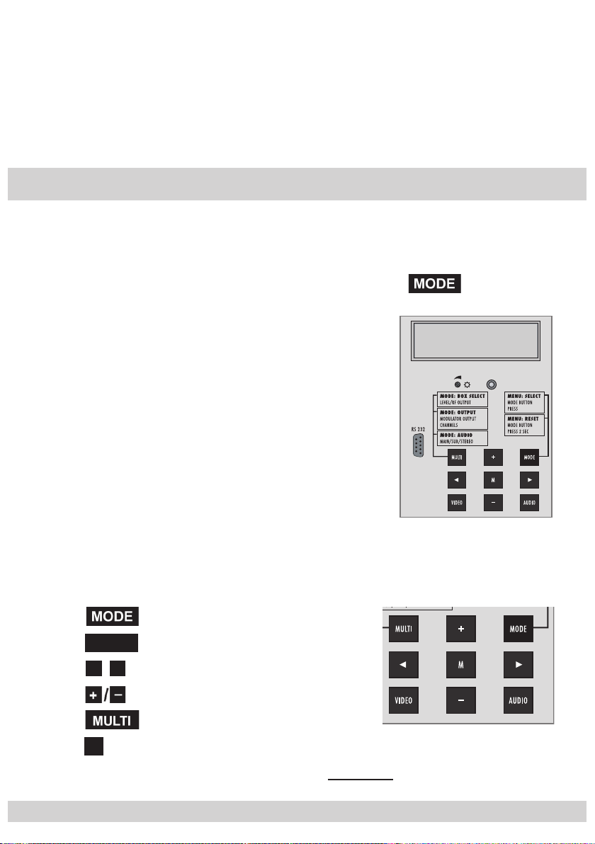
4 The operator control panel at a glance............................................................... 10
4.1 Menu items ..........................................................................................10
4.2 Operator control panel..........................................................................10
5 Programming .................................................................................................... 11
5.1 Preparation..........................................................................................11
5.2 The menus at a glance ..........................................................................12
5.3 Cassette programming ..........................................................................14
Selecting the Cassette ...........................................................................14
Setting the output channel......................................................................14
Querying software versions ...................................................................17
Modulator settings ................................................................................17
Setting output level of the channel strips ..................................................18
Producing a QAM signal for testing........................................................19
Inverting the user signal.........................................................................19
QAM monitoring ................................................................................. 20
Setting the input channel “A”................................................................. 20
Setting the hierarchical modulation “A” ...................................................21
Setting the input channel “B”................................................................. 22
Setting the hierarchical modulation “B” .................................................. 22
Setting the station filter / channel strip “A”.............................................. 22
Setting the station filter / channel strip “B”.............................................. 24
Scanning the station filter...................................................................... 25
Setting the QAM modulation ............................................................... 26
Setting the stuffing ............................................................................... 26
Network Information Table (NIT) ........................................................... 28
Saving settings .................................................................................... 29

- 3 -
- 3 -
1 Safety regulations
Important
• Assembly, installation and servicing must be carried out by an authorised
electrician.
• Switch off operating voltage before the start of assembly or service work or
pull out the mains plug.
• Install the system …
- in a dust-free, dry environment
-
so that it is protected from moisture, vapours, splashing water and damp
- somewhere protected from direct sunlight
- away from the immediate vicinity of heat sources
- at an ambient temperature of < 50 °C.
•
Make sure the device is adequately ventilated.
Do not cover the ventilation slots.
• Beware of short circuits!
• No liability is accepted for damage caused by faulty connection or inexpert
handling.
• Observe the relevant norms, regulations and guidelines on the installation and
operation of antenna systems.
•
Earth the SAT receiver using the equipotential bonding rail in accordance with
DIN EN 50083 and VDE 0855.
• Do not perform installation and service work during thunderstorms.
Take action to prevent static discharge when working on the device.
2 General information
2.1 Packing contents
1 Cassette HDMT 473 MX or HDMT 474 MX or HDMT 475 MX
2 HF connection cables
1 CD (Assembly instructions)

- 4 -
- 4 -
2.2 Technical data
The devices meet the following EU directives:
73/23/EEC, 89/336/EEC
The product fulfils the guidelines and standards for CE labelling.
HF input:
Frequency range: 177.5 … 226.5 MHz, 474 … 858 MHz
Frequency raster: CCIR
Level range: 30 dBµV … 80 dBµV (16 QAM 2/3, GI=1/4, 8k)
HF output:
HDMT 473 MX
Frequency range: 112 MHz … 306 MHz
HDMT 474 MX
Channels: S21 … S41
Frequency range: 306 MHz … 466 MHz
Channel raster: 8 MHz
HDMT 475 MX
Channels: C21 … C69
Frequency range: 474 MHz … 858 MHz
Channel raster: 8 MHz
Output level: Typ. 90 dBµV
Output impedance: 75 Ω, nominal
Connections:
HF inputs: 2 IEC connectors
HF output: 1 IEC socket
Connection strip (10-pin):
For supply voltages and control circuits
Socket RS 232:
Update interface

- 5 -
- 5 -
2.3 Description
The Cassettes convert two COFDM
modulated signals into one QAM-modulated
data flow. The Cassettes are controlled via the head end.
Each Cassette has two terrestrial inputs and one HF output.
Each Cassette is equipped with two channel strips (“A” and “B”). The channel strips
consist of the digital terrestrial tuners, the digital signal preparing units and the
output QAM converter. The Cassettes´ channel strips are indicated by
“Bx…A” or
“Bx…B” in the control unit display.
The integrated TP module (Transport Stream Processing) processes the data
from the demodulated transport flow. In this way, service information can be
modified (NIT – Network Information Table), stations can be selected and data
rates can be increased (Stuffing). The TP module allows to create a new data
flow out of the stations selected individually from the two data flows.
The prepared input signals are transmitted to the HF output collector of the head
end via the HF output socket. The output level of the Cassettes can be set with the
level regulator (max. –20 dB) at the output collector of the head end.
The operating software of the Cassette can be actualised via the 9-pin SUB-D-
socket, using a PC or notebook and the software “BE-Flash”. You can find the
current operating software of the Cassettes on the website “www.gss.tv”.
After the head end has been switched on, the software version of the control
unit is displayed briefly in the two-line LC display and afterwards the type of
Cassette of the first slot.
Approximately five minutes after the last button has been pressed, the software
version of the control unit is displayed.
The Cassettes are designed for use in the following head ends:
– STC 316
– STC 332
– STC 1200
– STR 19–8

- 6 -
- 6 -
2.3.1 Software versions
Cassette
The inquiry of the Cassettes´ software versions is described in chapter 5.
Control unit
If necessary, you can call up the display of the software version of the control
unit manually:
• Hold down any two keys of the control unit simultaneously until the display
goes dark and
the software version, e.g. “
V 35
”, is displayed.
2.3.2 How the TP module works
When converting the COFDM signal to a QAM-modulated cable signal, the
demodulated data stream can be accessed via the integrated TP module. This
data stream, also called transport stream, contains several stations with all their
components (video, audio, data and service information), which can be changed
using the TP module.
The individual functions
Station filter
Individual stations can be deleted. This reduces the data rate and, consequently,
a lower output symbol rate can be selected.
Stuffing
The transport stream is padded out using what is known as zero data. This
increases the data rate and, consequently, the output symbol rate. Changing
the output symbol rate suitably alters the bandwidth used (halving the output
symbol rate roughly halves the bandwidth at the output).
Changing service information
The transport stream contains data in the form of tables which the receivers eval-
uate and require for convenient use. The TP module can change the “Network
Information Table” (NIT) to the
new data of the stations
. The NIT contains data
which the set-top box needs for the automatic search function.

- 7 -
- 7 -
2.3.3 Explanation of the term “symbol rate”
Modulation schemes such as QPSK and QAM transmit multiple bits simultane-
ously. These are referred to as symbols. In addition to the user data flow which
transmits video and audio information, error correction bits are transferred. The
FEC number states the ratio of error correction bits to user bits. The output sym-
bol rate is calculated as follows:
256-QAM: SR (A) = FEC x 1/4x SR (E)
128 - Q A M: SR (A) = FEC x 2/7x SR (E)
64-QAM: SR (A) = FEC x 1/3x SR (E)
32-QAM: SR (A) = FEC x 2/5x SR (E)
16- QAM: SR (A) = FEC x 1/2x SR (E)
4-QAM: SR (A) = FEC x 1/1x SR (E)
Example:
Output symbol rate SR (A) = 64-QAM,
FEC= 3/4,
Input symbol rate SR (E) = 27,500 kilosymbols per second
SR (A)
= 3/4x 1/3x 27,500 kilosymbols/s
SR (A)
=
6,875 kilosymbols/s
Note:
If no “FEC” is stated in the station lists, it can be assumed to be
“FEC =
3/4
”.
Reception from a transponder with a very low symbol rate
(SCPC station)
The extremely low data rate means that the output symbol rate is very low. If
there are reception problems with different digital receivers, set QAM modula-
tion with stuffing to a higher value.
Defined symbol rates
Some cable operators specify a fixed symbol rate (e.g. 6,900 kilosymbols per
second).

- 8 -
- 8 -
2.3.4 Bandwidth-efficient assignment of cable channels with low bandwidths
(SelecPlex®)
Channels with low bandwidths are the result of filtering out stations which are
not required. These “narrow” channels can then be arranged in one channel to
save space. To do this, activate fine tuning in the “Output channel” menu (as-
signment outside the official channel raster).
Note:
The required bandwidth is roughly equal to the symbol rate plus 20% in MHz.
ESC 1
Nile TV
Nile News
TVP 1
TVP 2
TVP 3
Viva
Gala
3 MHz
64 QAM
2.5 Ms/s
4 MHz
64 QAM
3.3 Ms/s
S21 S22 S23 S24
TV 5
RTM 1
ESC 1
RAI UNO
DW TV
RTP
SISAL TV
TV Bulgaria
Mediolanum
Nile TV
Nile News
Super Sport
Viva
Gala
Fantasy
Cine 5
TVP 1
TVP 2
TV Polonia
TVP 3
Astra 19,2° East Eutelsat 7° EastTürksat 42° EastEutelsat 13° East

- 9 -
- 9 -
3 Assembly
3.1 Installing the Cassette
Warning
Before inserting or changing Cassettes, pull the mains plug of the head end
out of the mains socket.
•
Unscrew the fastening screws from the bracket in the head end.
• Insert the Cassette into a free slot and push it into the housing.
• Align the Cassette and gently make it contact with the connections of the
circuit board and the HF bus bar.
• Fasten the Cassette with the 1screws.
3.2 Connecting the Cassette
•
Connect the HF input cable with the input sockets “
INPUT A
” 3
(channel strip “A”) and “
INPUT B
” 1(channel strip “B”).
•
Connect the head end to the mains power supply.
—> The Cassette is now ready for operation.
loop-through
OUTPUT B
loop-through
OUTPUT A
INPUT B
INPUT A
RS 232 UPDATE
+24
BREITBA
C101
L104
L100
L101
L103
C100
LNC-
+18V
ROT
+18V
Anschl.
GRUEN
INPUT OUTPUT OUTPUT INPUT

- 10 -
- 10 -
Note:
The operating software of the Cassette can be updated via the socket
“RS 232 UPDATE” 5(9-Pin-Sub-D) by means of a PC or notebook.
Use the “BE-Flash” software as the update software. You can find the current
operating software of the Cassettes on the website “www.gss.tv”.
4 The operator control panel at a glance
4.1 Menu items
Program the Cassette using the keys on the head end control unit. The two-line
display of the control unit then shows the menus.
You can select the following main menu items with the
button:
– Cassette
– Output channel
– Input channel “Bx…A” / “Bx…B”
– Hierarchical modulation “Bx…A” / “Bx…B”
– Station filter “Bx…A” / “Bx…B”
– QAM modulation
– Stuffing
– Network Information Table (NIT)
4.2 Operator control panel
You can individually select the menus and menu items step-by-step using the
key pad of the head end:
scrolls forward through the menu
AUDIO
scrolls backward through the menu
▶
◀/
select parameters in the menus
set values, initiate actions
selects sub-menus
Msaves all entries
The parameters to be set are displayed underlined (cursor).
BE–Remote V 35
please wait . . .

- 11 -
- 11 -
5 Programming
The following examples show how the
HDMT 474 MX
Cassette is programmed;
the output channels can be set from S21 … S41. Set the other Cassettes listed
in the same way.
5.1 Preparation
Notes:
– Using the menu
“
LEVEL CONTROL
”
the Cassette generates an equally power-
ful HF carrier on the video carrier frequency of the channel. In this way, the
Cassette‘s level can also be set with an analogue TV test receiver set to the
video carrier frequency of the channel.
– In order to prevent interference within the head end and the cable system,
the output level of the digital Cassettes must be lowered by approx. 10 dB
at 64 QAM and by approx. 4 dB at 256 QAM compared to analogue Cas-
settes.
–
If the
button is pressed for more than 2 seconds in all menus the
programme returns to the menu “Selecting the Cassette”.

- 12 -
- 12 -
5.2 The menus at a glance
Bx 1A
LEVEL HF OUT:
OUTPUT:
00…-7
Bx 1A
RANDOM 6900
OUTPUT:
kBd
Bx 1A
Spectrum
OUTPUT:
normal normal / inverse
Bx 1A
LEVEL CONTROL
OUTPUT:
Bx 1A
Modulator:
OUTPUT:
on on / off
Überwachung
/
KDG
Monitoring / KDG
Bx 1A MODE:
Ueberwachung
-64 … +64
Bx 1A
MUX 7 / MTP15
VERSION:
▶
▶
Bx 1A
S21
OUTPUT:
(306.00)
Bx 1A
C5-12,S3-24
TWIN-SAT
C07
Böx 4
C5-12,S3-24
TWIN-SAT
C07
Box 2
S21-S41
***
QPSK-DSL
S23
+
t > 10 s
Ein/On BE–Remote
Please wait …
V 35
Box 1
S21-S41
COFDM-MUX
M**
S21
Bx 1A
S21 0
OUTPUT:
(306.00)

- 13 -
- 13 -
Bx 1A
C34 (578.0)
INPUT:
OK
+–
/
Bx 1A
Priority:
INPUT:
high
Bx 1B
C40 (626.0)
INPUT:
OK
+–
/
Bx 1B
Priority:
INPUT:
high
Bx 1A
C40 0
INPUT:
OK
Bx 1A
C34 0
INPUT:
OK
◀-64 … +64
-64 … +64
▶
◀
▶
Bx 1A
read …
FILTER:
Bx 1B
read …
FILTER:
Bx 1A
SR=6875 (5800)
STUFFING:
Bx 1B
Filter => read
FILTER:
Bx 1A
off
NIT:
=> Make
M
Bx 1B
ZDF
TV + 01/08 ▶
◀/
+–
/
▶
◀/
+–
/
+–
/
Bx 1A
64-QAM
QAM-MODE:
▶
Bx 1A
Das Erste
TV + 01/18 ▶
◀/
AUDIO
on / off
▶
+–
/

- 14 -
- 14 -
5.3 Cassette programming
• Switch on the head end.
—> The display shows the software version of the head
end (e.g. V 35).
—> The processor reads the Cassettes‘ data
(approx. 10 seconds).
Selecting the Cassette
• If necessary select the Cassette you want to program
(Box…) by repeatedly pressing the button .
• Press the button.
—> The menu “Setting the output channel” – “OUTPUT”
is activated.
Setting the output channel
• By pressing , set the desired output channel.
—> The channel range that can be set depends on the
type of Cassette used.
Bx 1A
C5-12,S3-24
TWIN-SAT
C07
Böx 4
C5-12,S3-24
TWIN-SAT
C07
Box 2
S21-S41
***
QPSK-DSL
S23
+
t > 10 s
Ein/On BE–Remote
Please wait …
V 35
Box 1
S21-S41
COFDM-MUX
M**
S21
Bx 1A
C5-12,S3-24
TWIN-SAT
C07
Böx 4
C5-12,S3-24
TWIN-SAT
C07
Box 2
S21-S41
***
QPSK-DSL
S23
+
t > 10 s
Ein/On BE–Remote
Please wait …
V 35
Box 1
S21-S41
COFDM-MUX
M**
S21
-64 … +64
▶
▶
Bx 1A
S21
OUTPUT:
(306.00)
Bx 1A
S21 0
OUTPUT:
(306.00) -64 … +64
▶
▶
Bx 1A
S21
OUTPUT:
(306.00)
Bx 1A
S21 0
OUTPUT:
(306.00)

- 15 -
- 15 -
Setting the frequency offset (fine tuning)
• If necessary press the
▶
button until “0” also appears in
the display.
• Use the keys to set the offset (-64 … +64).
• Use the ◀
/
key to return to the channel setting.
Note:
Using the Cassette HDMT 473 MX the menu “Setting the
output frequency” appears instead of “Setting the output
channel”.
Bx 1A
112.00 MHz
OUTPUT: Bx 1A
MUX 7 / MTP15
VERSION:
Bx 1A
Modulator: on
OUTPUT:
▶
◀/
+–
/
The QAM signal is transmitted with a bandwidth of 8 MHz.
This means that you can only use the channel centre fre-
quency of the existing channel raster in the range of chan-
nels S21 … C69 (frequency raster 8 MHz). The frequency
raster is 7 MHz in the range of the lower channel ranges
(channels S2 … S20). If one uses the existing channel
raster here, this will result in interference (overlapping) of
the 8 MHz QAM signal packages and thus transmission
problems. For programming in this channel range, we rec-
ommend to calculate the output frequency of the QAM
modulator,
… starting with the upper output frequency of the Cas-
sette listed in the “Specifications” going back in steps
of 8 MHz, or
… starting with the lower output frequency of the Cas-
sette listed in the “Specifications” mov
ing up in steps
of 8 MHz.

- 16 -
- 16 -
Channel
Channel centre
frequency
[MHz
]
S 21 306.00
S 22 314.00
S 23 322.00
S 24 330.00
S 25 338.00
S 26 346.00
S 27 354.00
S 28 362.00
S 29 370.00
S 30 378.00
S 31 386.00
S 32 394.00
S 33 402.00
S 34 410.00
Channel
Channel centre
frequency
[MHz
]
S 35 418.00
S 36 426.00
S 37 434.00
S 38 442.00
S 39 450.00
S 40 458.00
S 41 466.00
C 21 474.00
C 22 482.00
C 23 490.00
C 24 498.00
C 25 506.00
C 26 514.00
C 27 522.00
Channel
Channel centre
frequency
[MHz
]
C 28 530.00
C 29 538.00
C 30 546.00
C 31 554.00
C 32 562.00
C 33 570.00
C 34 578.00
C 35 586.00
C 36 594.00
C 37 602.00
C 38 610.00
C 39 618.00
C 40 626.00
C 41 634.00
Channel
Channel centre
frequency
[MHz
]
C 42 642.00
C 43 650.00
C 44 658.00
C 45 666.00
C 46 674.00
C 47 682.00
C 48 690.00
C 49 698.00
C 50 706.00
C 51 714.00
C 52 722.00
C 53 730.00
C 54 738.00
C 55 746.00
Channel
Channel centre
frequency
[MHz
]
C 56 754.00
C 57 762.00
C 58 770.00
C 59 778.00
C 60 786.00
C 61 794.00
C 62 802.00
C 63 810.00
C 64 818.00
C 65 826.00
C 66 834.00
C 67 842.00
C 68 850.00
C 69 858.00
• With HDMT 473 MX use the
▶
◀/
buttons to place the
cursor under the respective digit to be changed and use
the
keys to set the output frequency.
• Press the button.
—> The menu “Setting the input channel ‘A’ ”
– “Bx 1A INPUT:” is activated (page 20).
or
• Press the button.
—> The sub-menu “Querying the software versions” –
“
VERSION:
” is activated.

- 17 -
- 17 -
Querying software versions
—>
The software versions of the Cassette (e.g. MUX 7)
and the TP module (e.g. MTP15) are
indicated.
• Press the button.
—> The menu “Modulator settings” –
“OUTPUT: Modulator” is activated.
Modulator settings
If you do not need the output channel of this modulator you
can switch it off.
• By pressing the buttons, switch the modulator
(HF output) “on” (default setting) if necessary or switch it
“off”.
• Press the button.
—>
The menu “Setting output level of the channel strips“ –
“OUTPUT:
LEVEL HF OUT:
” is activated.
Bx 1A
MUX 7 / MTP15
VERSION:Bx 1A
MUX 7 / MTP15
VERSION:
Bx 1A
Modulator:
OUTPUT:
on on / off
Bx 1A
Modulator:
OUTPUT:
on on / off

- 18 -
- 18 -
Setting output level of the channel strips
This setting is not urgently necessary with these Cassettes.
• Press the button.
—> “OUTPUT: LEVEL CONTROL” appears in the display.
Note:
In this mode a digital carrier is set to the analogue picture
carrier frequency of the output channel of the respective
channel strip. Thus you can measure the absolute output
level using an analogue test receiver.
•
Measure the output level of the channel strip using the con-
nected antenna test receiver.
• Press the AUDIO button to activate the menu
“OUTPUT: LEVEL HF OUT:”.
• Set the
output level of the channel strip incrementally from
“0
” to “
– 7” dB
by pressi
ng
.
• Press the button twice.
—> The menu “Producing a QAM signal for testing” –
“OUTPUT: RANDOM” is activated.
Bx 1A
LEVEL HF OUT:
OUTPUT:
00…-7
Bx 1A
LEVEL CONTROL
OUTPUT:
Bx 1A
LEVEL HF OUT:
OUTPUT:
00…-7
Bx 1A
LEVEL CONTROL
OUTPUT:

- 19 -
- 19 -
Producing a QAM signal for testing
The Cassette generates a QAM signal for testing,
without
there having to be an input signal.
In the second menu line, the corresponding output symbol
rate e.g. “6900 kBd”
(=
6,900
kilosymbols per second) is shown.
• Press the button.
—> The menu “Inverting the user signal” –
“OUTPUT: Spectrum” is activated.
Inverting the user signal
For exceptions and “older” digital cable receivers, the spec-
tral position of the user signal can be inverted
(“inverse”).
• By pressing , set the spectral position “normal” or
“inverse”.
• Press the button.
—> The menu “QAM monitoring” – “MODE:”
is activated.
Bx 1A
RANDOM 6900
OUTPUT:
kBd
Bx 1A
RANDOM 6900
OUTPUT:
kBd
Bx 1A
Spectrum
OUTPUT:
normal normal / inverse
Bx 1A
Spectrum
OUTPUT:
normal normal / inverse

- 20 -
- 20 -
QAM monitoring
In this menu the signal at the Cassettes´ output is defined if
there is no input signal available. Thus an automatic moni-
toring of the QAM modulated output signal is possible.
– “Ueberwachung” (monitoring):
For monitoring with the Monitoring Cassette a single
carrier is output.
– “KDG”:
For customer specific applications a QAM modulated
data flow is output.
• Use
buttons to select “Ueberwachung” or “KDG”.
• Press the button.
—>
The menu “Setting the input channel ‘A’ ” –
“Bx 1A INPUT:” is activated.
Setting the input channel “A”
Notes:
–
If three dots “ …” appear in the second line of the display,
the Cassette is in the “station search” mode.
Please wait until the process has finished.
Once the HF receiver has synchronised to the input signal,
“OK” is displayed.
– If “– –” appears in the second line of the display, there
is no input signal present. Check the configuration of the
antenna system and head end as well as the preceding
settings of the Cassette
.
Überwachung
/
KDG
Monitoring / KDG
Bx 1A MODE:
Ueberwachung Überwachung
/
KDG
Monitoring / KDG
Bx 1A MODE:
Ueberwachung
Bx 1A
C34 (578.0)
INPUT:
OK
+–
/
Bx 1A
C34 0
INPUT:
OK
◀-64 … +64
▶
Bx 1A
C34 (578.0)
INPUT:
OK
+–
/
Bx 1A
C34 0
INPUT:
OK
◀-64 … +64
▶
This manual suits for next models
2
Table of contents
Other Grundig Modulator manuals