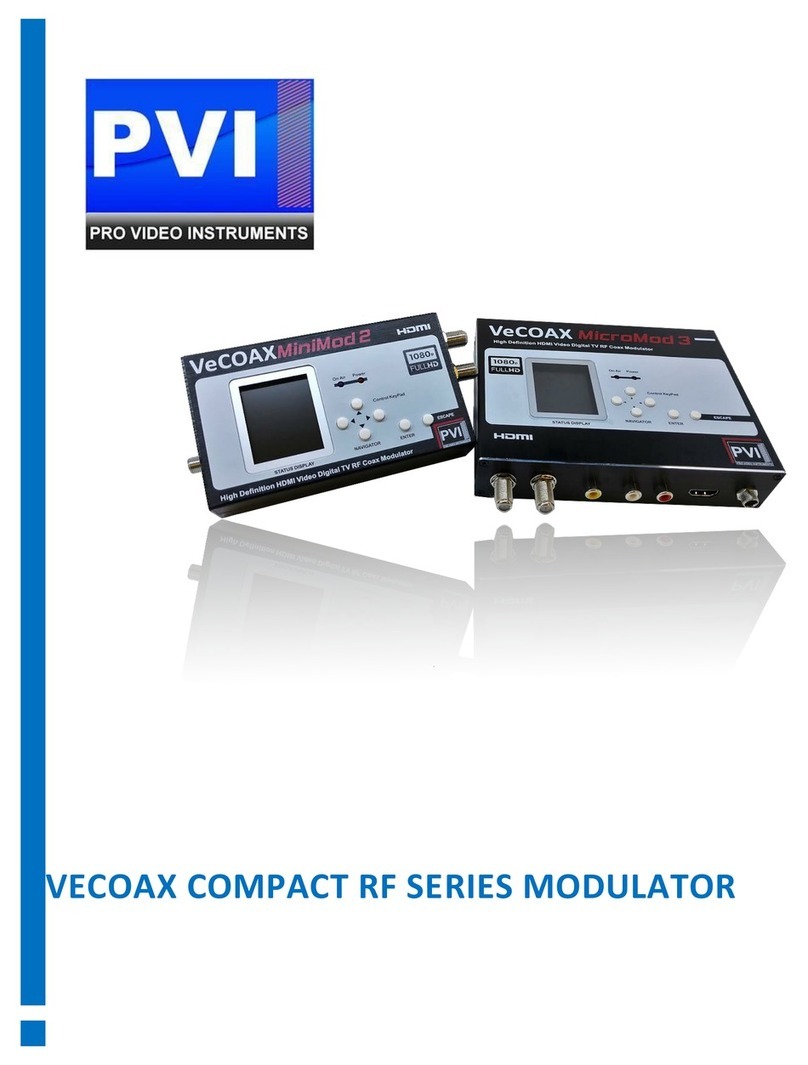
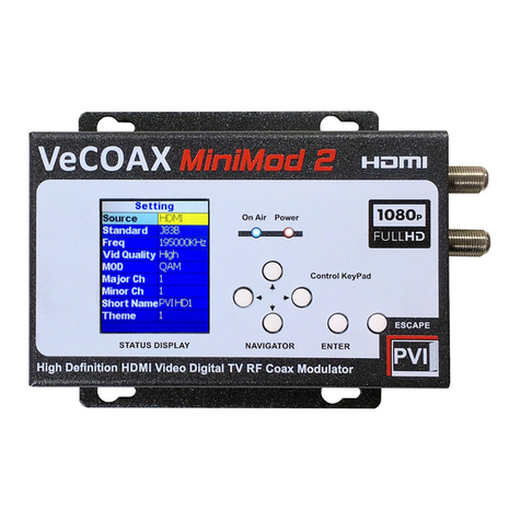
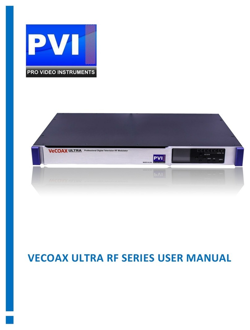
PVI VECOAX MINIMOD 2 PLUS User manual

VECOAX MINIMOD 2 PLUS
INSTRUCTION MANUAL V1.4 JULY 2022
The information in this document is subject to change without notice. Although PVI strives to improve and update our documentation as time passes,
ProVideoInstruments is not responsible for any misinformation or incompleteness. Any concerns may be brought forward to our support staff.

2 | P a g e
ProVideoInstruments –Minimod 2 Plus
Table of Contents
Before Installation................................................................................................................................................... 5
Technical Specifications.......................................................................................................................................... 6
Modulation Specs ................................................................................................................................................... 7
•ATSC or QAM............................................................................................................................................ 7
•ISDB-T(b)................................................................................................................................................... 7
•DVB-C........................................................................................................................................................ 8
•Video Quality............................................................................................................................................ 8
•Audio Codec ............................................................................................................................................. 8
Unit Overview ......................................................................................................................................................... 9
•Panel......................................................................................................................................................... 9
•LEDS.......................................................................................................................................................... 9
•Peripheral Interface ................................................................................................................................. 9
•Back Panel ................................................................................................................................................ 9
•TV Standards Supported ........................................................................................................................ 10
LCD Configuration Menu....................................................................................................................................... 11
•Channel setup ............................................................................................................................................ 11
•Channel setup(Continued)......................................................................................................................... 12
•Modulation Options................................................................................................................................... 13
•Advanced Settings...................................................................................................................................... 14
•Advanced Settings(Continued) .................................................................................................................. 15
•General Setup ............................................................................................................................................ 16
•Help & Info................................................................................................................................................. 16
Combining With Other TV Coax Signals................................................................................................................ 17
•Community Channel Insertion (Service Provider) ..................................................................................... 17
•How to Assign A Channel........................................................................................................................... 18
•Generic Setup (USA/Canada/Mexico)........................................................................................................ 19
•Installing Multiple Modulators .................................................................................................................. 21
•Installing Multiple Modulators (Continued) .............................................................................................. 22
ATSC Over-the-Air TV with HDMI Modulation...................................................................................................... 23
Exsisting Cable TV with HDMI Modulation ........................................................................................................... 26

3 | P a g e
ProVideoInstruments –Minimod 2 Plus
DVB-T Over-the-Air TV with HDMI Modulation.................................................................................................... 29
ISDB-T(b) Over-the-Air TV with HDMI Modulation.............................................................................................. 32
DVB-C Cable TV with HDMI Modulation............................................................................................................... 35
Web Configuration / Remote Control................................................................................................................... 38
•Assigning a Static IP.................................................................................................................................... 39
•Network Connection Via Windows PC................................................................................................... 39
•Network Connection Via Mac OS X........................................................................................................ 39
•Connecting to the unit............................................................................................................................... 40
•Main Info Screen........................................................................................................................................ 40
•Channel Setup............................................................................................................................................ 41
•Modulator .................................................................................................................................................. 43
•Advance Settings........................................................................................................................................ 44
•General Setup ............................................................................................................................................ 46
•Help & Info................................................................................................................................................. 47
•ATSC (8VSB) Channel Plan - North America............................................................................................... 48
•J.83B Channel Plan - North America.......................................................................................................... 49
•DVB-T Channel Plan - Europe, Colombia & Asia ........................................................................................ 50
•ISDB-T(b) Channel Plan - South America ................................................................................................... 51
•DVB-C (J.83A/C) Channel Plan.................................................................................................................... 52
Notes..................................................................................................................................................................... 53
•Warranty ................................................................................................................................................ 53
•Important Safety Instructions ................................................................................................................ 53
•FCC Class B Equipment........................................................................................................................... 54
Trouble Shooting................................................................................................................................................... 56
•The video and the audio from HDMI source are not synchronized on TV ............................................ 56
•My HDMI source cannot be viewed on TV but other channels can be viewed..................................... 56
•The ON-AIR doesn't stay solid Green all the time.................................................................................. 56
•How do you get the best video quality on TV with the modulator?...................................................... 56
•How do I know my TV supports ATSC (8VSB) or J.83B standard?.......................................................... 56
•Some or most channels are instable or cannot be viewed on TV.......................................................... 57
•Audio from HDMI source is skipping or stuttering on TV ...................................................................... 57
•How do I replace an old modulator with the Minimod 2 PLUS ............................................................. 57
5 | P a g e
ProVideoInstruments –Minimod 2 Plus
Before Installation
Unit out of the box is set to Clear QAM (Digital Cable) on Channel 77.1. Connect it to your TV's tuner and auto
scan for digital TV to find the unit. No adjustments are needed to be done on the unit for a single channel unit.
If installing multiple, Refer to Installing multiple units section of the manual.
If your TV does not support Digital Clear QAM Cable, switch the unit to ATSC using the menu function. Under
the General setup in the menu, switch the TV standard to US AIR ATSC. Use the ◄► to move the cursor, and
press RETURN to save and escape. The unit defaults to channel 14.1 on ATSC. For any customization, continue
through the manual below or use the Generic setup on Page 19.
Things to keep in mind during installation:
1. Each unit must be on different frequencies if installing more than one unit. 6mhz apart for ATSC and
QAM. Refer to Installing multiple units section of the manual.
It's not recommended to daisy chain RF in RF mix out on each unit. There is a built-in attenuation on
the RF mix-in, which lowers the signal of each unit by 10db. A coax splitter or combiner must be used
to combine all the RF signals into one for your cable distribution
2. If combined with over-the-air antenna signals, Verify your local ATSC signal Frequencies used in your
local area. The Physical Channel, not the channel number, which is the Virtual Channel displayed on
your TV, is the Virtual Channel. Rabbitears.info provides this information combined with our ATSC
frequency chart included in this manual. You must ensure that you do not broadcast on the same
physical Frequency as your local stations to work correctly.
3. If combining with existing coax cable signals such as a Service provider or other modulators, see
Combining with other TV Signals
For any customization, continue through the manual below.

6 | P a g e
ProVideoInstruments –Minimod 2 Plus
Technical Specifications
HDMI Input resolution: 1080p | 1080i| 720p| 576p| 576i| 480p| 480i @ 24|50|60fps
Output Resolution: Same as input
HDMI Audio Format: Dolby Digital Stereo LPCM
RF frequency range: 5 - 999 MHz
RF Channel Bandwidth: 6/7/8 MHz Model specific to the broadcast format
Channel Range: 2-83 ATSC Mode | 2-158 QAM mode
RF Output power: -8dBm | ~40dBmv
RF Connector type: F-Type Dual
Coaxial cable Characteristic impedance: 75Ω
Coaxial cable support types: RG59 | RG6
RF transmission distance: ≤300m(~900 ft) RG59 | RG6 coaxial standard cable
Max working current: 850mA @ 12 volts
Power adapter format Input: AC 100V~240V 50HZ/60Hz, DC12V/1A
Operating Temperature range: -10 to +45℃
Storage Temperature range: -20 to +60℃
Operating Humidity range: 10 to 90%RH (No Condensation)
Storage Humidity range: 5 to 95%RH (No Condensation)
Units Dimensions (LxWxH): 8 in X 3.5 in X 1.25in (203.2mm×88.9mm×31.75mm)
Carton Dimensions (Individual): 11 in. (L) 6 in. (W) 9 3 in (H);
Shipping Weight: 1 lbs.

7 | P a g e
ProVideoInstruments –Minimod 2 Plus
Modulation Specs
•ATSC or QAM
Modulator Type ATSC-Air (8VSB) or QAM-Cable (J.83B)
Frequency Range 50 MHz to 860 MHz
Channel Bandwidth 6 MHz
Technique ATSC 8VSB
J.83B 64QAM, 128QAM, 256QAM
MER ≥35 dB
DVB-T
Frequency Range 50 MHz to 860 MHz
Channel Bandwidth 6 MHz (Colombia/Panama), 7 MHz (Australia),
8 MHz (Europe, New Zealand)
Technique 16QAM, 64QAM, QPSK
Carrier Type 2K. 8K
Code Rate 1/2, 2/3, 3/4, 5/6, 7/8
Guard Interval 1/4, 1/8, 1/16. 1/32
•ISDB-T(b)
Frequency Range 50 MHz to 860 MHz
Channel Bandwidth 8 MHz
Technique 16QAM, 64QAM, DQPSK, QPSK
Carrier Type 2K. 4K, 8K
Code Rate 1/2, 2/3, 3/4, 5/6, 7/8
Guard Interval 1/4, 1/8, 1/16. 1/32
Interleave Mode 1, Mode 3, Disabled. Used for robustness of
Forward Error Correction (FEC).

8 | P a g e
ProVideoInstruments –Minimod 2 Plus
•DVB-C
Frequency Range 50 MHz to 860 MHz
Channel Bandwidth 8 MHz
Symbol Rate editable, 6.875 Mbps
Technique 16QAM, 32QAM, 64QAM, 128QAM, 256QAM
•Video Quality
Video quality has been optimized by determining the size and the speed of transmitting MPEG packets to the
TV. The Modulator adjusts the packet latency and delays variation automatically to reach the best video
quality and performance on the TV.
•Audio Codec
The Modulator automatically selects audio encoding to reach the best quality according to the local
modulation technique.
AC3 -2.1 Dolby Digital Audio coding applies to North America's ATSC (8VSB) broadcasting.
MPEG MPEG-2 Layer 1 - audio coding applies to DVB-T broadcasting in Europe and South America.
ACC -Advanced Audio Coding for MPEG-4 applies to ISDB-T broadcasting in South America and certain

9 | P a g e
ProVideoInstruments –Minimod 2 Plus
Unit Overview
•Panel
2.4" color LCD
Keypad
•Return or Escape to the upper-
level menu and confirm the current
operation
◄►▲▼ Arrow keys to traverse between
fields or increase/decrease selected field value
Confirm the selection
•LEDS
Power solid Red Power Indication
ON-AIR solid Green Broadcasting RF out
•Peripheral Interface
Left Panel
RF-OUT Modulated RF output, 75Ω F
RF MIX IN Antenna or Cable RF Input Attenuated 15dbmv,
75Ω F
Not recommended for use of daisy chaining RF In to RF out on
multiple units
•Back Panel
Power DC 12V Input
HDMI IN HDMI Input up to
1080P
Web Control Web Access Control
Update USB Interface
Updates

10 | P a g e
ProVideoInstruments –Minimod 2 Plus
•TV Standards Supported
Cable TV (USA) J.83B
Over-the-Air TV (USA) ATSC (8VSB), ATSC 3.0(future)
Cable TV (EU, SA) DVB-C (J.83A/C)
Over-the-Air TV (CO) DVB-T
Over-the-Air (SA) ISDB-T(b)

11 | P a g e
ProVideoInstruments –Minimod 2 Plus
LCD Configuration Menu
•CHANNEL SETUP
Television Standard –Current Television Standard is currently used. To change the standard, use the General
setup menu to adjust. Depending on the standard used for Modulation, different options appear to change
the available Channel by plan numbers, such as UK standards or EU standards.
Channel by Plan –Select Channel by the FCC Channel, automatically assigning the correct Frequency, Major,
and Minor channel numbers. The Channel by Plan method is straightforward in setting up the unit.
Press◄► to show the channel table to select, ▲▼ to traverse, and OK to select Channel output frequency
from the channel table.
Channel by Freq –Specific pick the Frequency you wish to broadcast on. Used more for customization of the
Frequency used and Virtual Channel number that displays on the TV
Press OK to edit Channel output frequency, ◄► to move the cursor and ▲▼ to change the Frequency in
range, and press RETURN to save and escape.
RF Out Level –Adjust the output of the RF level from the Modulator. The default is 45dbmv, the highest
output, and 25dbmv, the lowest.
Press◄► to change the RF output level between 25dbmv and 45dbmv.
Bandwidth –Adjust the available bandwidths for your standard. Only available in DVB-T, DVB-C, and ISDB-T
modes.
Press◄► to change modulation channel bandwidth.
Video-Input –HDMI by default. No other options for this Model.
Audio Input –HDMI by default. No other options for this Model.
Channel Main Number –Specify the channel number displayed on the TV. This is the main virtual channel
number. Only required to change if you wish to customize the channel plan layout XX.XX Example 10.XX
Press OK to edit HDMI channel number, ◄► to move the cursor and ▲▼ to
change channel number, and press RETURN to save and escape.

12 | P a g e
ProVideoInstruments –Minimod 2 Plus
•CHANNEL SETUP(CONTINUED)
Channel Sub Number - Specify the channel number displayed on the TV. This is the sub-virtual channel
number. Only required to change if you wish to customize the channel plan layout XX.XX Example XX.10
Press OK to edit the subchannel number, ◄► to move the cursor and ▲▼ to
change subchannel number, press RETURN to save and escape.
LCN Channel Number –Virtual Channel number used for DVB-T and ISDB-T TV Standards.
Press OK to edit LCN, ◄► to move the cursor, and ▲▼ to change LCN, press RETURN to save and escape.
Program Name –Name of the Channel that shows on the TV. Up to 7 characters can be used, including
spacing.
Press OK to edit the program name using the alphanumerical options on the display, and press RETURN to
save and escape.

13 | P a g e
ProVideoInstruments –Minimod 2 Plus
•MODULATION OPTIONS
Modulation Mode –Set the advance options for the modulation mode choice for the current TV standard,
such as QAM mode, Symbol rate, GI, or Code Rate, for example.
Technique press ◄► to change modulation technique.
Symbol Rate press OK to edit symbol rate in MHz, ◄► to move the cursor, and ▲▼ to change
symbol rate.
Code Rate press ◄► to change code rate.
Carrier Type press ◄► to change carrier type.
Guard Interval press ◄► to change guard band interval.
Interleaving press ◄► to change interleaving

14 | P a g e
ProVideoInstruments –Minimod 2 Plus
•ADVANCED SETTINGS
Advance settings must only be modified if your application, such as Community channel cable insertion or
applications, deems it necessary. Applications such as where the IDs need to be a specific ID to work correctly.
Default values are designed to work correctly for most applications. Please only change these if you clearly
understand Modulation and PSIP broadcast tables. Incorrect values can lead to unwanted results
Press OK to edit IDs, ◄► to move the cursor and ▲▼ to change values, and press RETURN to save and
escape.
Network ID –NIT ID for DVB-T, ISDB-T Standards. Network ID between 1 and 65535.
Original Network ID –NIT Original ID for DVB-T, ISDB-T Standards. Organization Network ID between 1 and
65535.
Transport Stream ID - Number for the Transport Stream. Transport Stream ID between 1 and 65535.
SID - Service Stream ID between 1 and 65535.
PMT PID –Program Map Table (PMT) Packet ID (PID) between 1 and 8191.
Video PID –Video Packet ID (PID) between 1 and 8191.
Audio PID –Audio Packet ID (PID) between 1 and 8191.
Service Provider –Name of the Service provider. Not required to use for most applications. Press OK to edit
the Service Provider name using the alphanumerical options on the display, and press RETURN to save and
escape.
Network Name - Press OK to edit the Network name using the alphanumerical options on the display, and
press RETURN to save and escape.
J83B IQ Mode –Invert the Phase rotation for compatibility reasons. The default works for most applications.
However, if injecting into the Cable provider set-top box, this step might be the last to make it work correctly
on the Community channel if the screen stays black.

15 | P a g e
ProVideoInstruments –Minimod 2 Plus
•ADVANCED SETTINGS(CONTINUED)
Changing MPEG Transport Stream (TS) parameters is not recommended unless you understand the MPEG PID
structure well or your Service Provider requires you to configure a specific Packet Identifier (PID) describing
the payload data for set-top box initialization.
Refer to Wikipedia for more information about MPEG Transport Stream structure.
https://en.wikipedia.org/wiki/MPEG_transport_stream https://en.wikipedia.org/wiki/Program-
specific_information
NID Network ID is contained in Network Information Table (NIT).
ONID Organization Network ID is contained in Network Information Table (NIT).
TSID Transport Stream ID is contained in Service Description Table (SDT).
SID Service ID contained in Service Description Table (SDT) to identify transport
stream.
PMT PID Program Map Table (PMT) PID contains the directory listing of all program map tables in the
transport stream, including the program number and the list of elementary streams.
Video PID Video content stream PID contained in MPEG transport stream for
demultiplexer to locate by sorting the incoming packets.
Audio PID Audio content stream PID contained in MPEG transport stream for
demultiplexer to locate by sorting the incoming packets.
Service Provider Name of the broadcaster responsible for the service availability or authority contained
in the Service Description Table (SDT).
Network Name Name of the network is contained in Network Information Table (NIT).

16 | P a g e
ProVideoInstruments –Minimod 2 Plus
•GENERAL SETUP
UI Language –Select the Language for the menu. Then, press◄► to change the on-screen-display language.
TV Standard –Select the TV standard you wish to use for your application. Press◄► to change modulator
standard type.
USA Cable J.83B, USA Air ATSC, ISDB-T, DVB-T, DVB-C, DTMB.
IP Mode –Select between DHCP(Client) or Manual mode. Press OK to edit IP Mode, ◄► to move the cursor,
and ▲▼ to change the value, press RETURN to save and escape.
IP Address –Current IP address assigned. In DCHP Mode, this will display your router's current IP address
assigned to the unit via the DHCP Server. Press OK to edit IP Address, ◄► to move the cursor, and change
value; press RETURN to save and escape.
Subnet Mask –IP subnet mask. Press OK to edit Subnet Mask, ◄► to move the cursor and ▲▼ to change
the value, and press RETURN to save and escape.
Gateway –IP Gateway. Press OK to edit Gateway, ◄► to move the cursor, and ▲▼ to change the value,
press RETURN to save and escape.
Keyboard Beep –Audio response when the keys are in use, off by default. Press◄► to turn the ON/OFF
keypad beep sound.
Factory Reset –Reset the unit to factory default. Press OK to reset and restore factory defaults.
•HELP & INFO
HW Version –Current Hardware version
SW Version –Current Software Version

17 | P a g e
ProVideoInstruments –Minimod 2 Plus
Combining With Other TV Coax Signals
To combine the existing TV broadcasting channels from a service provider, free Over-the-Air channels, or
other modulators, it's necessary to select an output frequency and output channel for the unit to broadcast on
that currently is not in use.
➢For ATSC, the channel information of your local over-the-air broadcasting or local Cable TV service can
generally be found online or from the channel listing table provided by your service provider.
Rabbitears.info has this information for you. Find an available frequency that is not in use and assign
your unit to that Channel or Frequency to ensure you do not overlap existing channels. A separate
detailed guide can be found below. ATSC over-the-air with HDMI Modulation
➢For business installers, a handheld spectrum analyzer up to 1 GHz can be helpful to make the
installation easier and faster, although it's not mandatory.
Suppose the output power level of the Modulator is too high. In that case, it may oversaturate the TV signals
delivered by service providers. It's necessary to lower the output power level using the menu function or use
an inline attenuator to reduce oversaturation if needed.
•COMMUNITY CHANNEL INSERTION (SERVICE PROVIDER)
Suppose the Modulator output will feed a Digital Cable Converter box or a set-top box. In that case, some
service providers offer a dedicated channel (and Frequency) for modulated video. In addition, some service
providers may need a specific PID to be configured by the Modulator for MPEG streams to be recognized by
the set-top box. Refer to the section of MPEG Transport Stream Parameters for PID setup. Again, engineers
provide this information, not the help desk service centers.
The Main Requirements need to make it work as follows:
1. Frequency
2. Program ID
3. Transport ID
Your service provider must provide this information to make it work. Enter this information within the unit
using the various menus

18 | P a g e
ProVideoInstruments –Minimod 2 Plus
•HOW TO ASSIGN A CHANNEL
Depending on the TV Standard of over-the-air broadcasting(ATSC) or Cable TV(QAM) used in your area, refer
to the corresponding appendix for Channel Plan information or use the guides found further within the
manual for your specific standard used when mixing with other coax cable signals.
The following information provides a generic setup for broadcasting your HDMI signal over RF. In some
applications, the default settings may work as a plug-and-play device if your local area channels as long as not
the same Frequency is used. Suppose a simple installation of converting your HDMI to an RF channel is
required. In that case, no other signals are used. Connect the coax cable to the Modulator to your TV or Coax
distribution systems such as the coax splitter and Auto scan on your TV for channels.
It is crucial to Select an unused or unimportant channel from the Channel Plan as the output frequency of
the Modulator. If you are unsure which output frequency to use for The Modulator, then use the default
frequency selected by the Modulator and see if that works. Suppose it does not, then proceed below to the
generic setup.
Pick a frequency between channel gap, make sure it is 6 MHz ATSC|QAM or 8 MHz for EU and Latin America
away from the previous and the following channels. Then, use the recommended Frequency indicated on the
corresponding Channel Plan appendix or the Channel by plan method to assign the Frequency per the channel
number selected automatically. Modulated output frequency and channel number can be configured from the
LCD menu or Web Configuration page.

19 | P a g e
ProVideoInstruments –Minimod 2 Plus
•GENERIC SETUP (USA/CANADA/MEXICO)
The on-screen-display language can be changed by going to General Setup →UI Language.
1. Power on the Modulator with a power adapter included in the package if you have not done so
already.
2. Connect your coax cable to the RF out of the Modulator. If you wish to use the
Minimod 2 Plus inline with your existing Coax cable without a splitter, you may
use the RF Mix in and RF out ports.
Otherwise, connect your RF out from the Modulator to a Coax
splitter/combiner you use with your antenna system. It might be required to reduce the RF output of
the Modulator to prevent signal loss from your antenna or other coax channels.
3. Don't connect the HDMI source to the Modulator just yet. We do this in a later step.
4. Now would be the time to assign your Modulator to the TV standard supported by your TV sets. Most
TVs have dual tuners for USA Air ATSC or USA Digital Cable. If you are unsure, use the default USA
Digital Cable setting or switch to USA Air ATSC as its required to support USA AIR ATSC by default on all
TVs sold after 2008.
If some of the TVs refuse to pick up the Channel during your auto-scan, switch to USA Air ATSC if you
have not done so already and rescan.
5. Go through the LCD menu screen on the Modulator to configure the settings for the TV standard
required for your setup. If you are using the default settings, then skip these steps.
Press OK to go to the main menu, and General Setup →TV Standard, → select USA AIR ATSC or USA
Cable J.83B. The Modulator is now set up to output an ATSC or QAM Digital signal.
6. To select a channel to broadcast on, we have two options. Channel by Plan or Channel by Frequency
a. Channel Setup →Channel by Plan → select from the existing channel plan for the Modulator
frequency with ◄►▲▼ keys. Then, press OK to select the Channel you wish to broadcast on.
b. Channel Setup → Channel by Frequency →press OK to edit Frequency in MHz with ◄►▲▼
keys.

20 | P a g e
ProVideoInstruments –Minimod 2 Plus
7. Adjusting the Virtual Channel, which is the channel number displayed on the TV, can be done using the
following:
a. Channel Setup →Channel Main Number →press OK to edit the channel number
with◄►▲▼ keys
b. Channel Setup →Channel Sub Number →press OK to edit the subchannel number with
◄►▲▼ keys
Channel Setup →Program Name→ press OK to edit the channel name using the alphanumerical
keypad. Up to 7 Characters with spaces included are allowed.
The default channel name is PVI HD1.
8. Hit return to save the settings and return to the main screen
9. Turn on the TV and begin the Autoscan feature. Refer to the user's
manual of your TV on how to Auto Scan for channel detection if you
are unsure how.
10. Change the TV channel to the channel number entered in step 6. The
default channel is channel 77.
11. The PVI TEST PATTERN is displayed on the TV as long as no HDMI is connected.
12. Connect the HDMI from your video players or input devices like DVD player, Satellite TV Set-Top Box,
Video Stream, Security monitors... etc., to the HDMI Input on the Modulator. It is recommended to set
the video output of the HDMI device with a fixed resolution at 1080p or 720p.
13. Once the Modulator source is detected and modulated, the ON-AIR on the panel glows solid Green,
and you should see your HDMI Video on the TV.
Table of contents
Other PVI Modulator manuals

PVI
PVI Vecoax Compact RF Series User manual

PVI
PVI VeCOAX ULTRA-HDMI-QAM-IP User manual

PVI
PVI Vecoax MiniMod 2 User manual

PVI
PVI VeCOAX MicroMod 3 User manual

PVI
PVI VECOAX ULTRA RF Series User manual

PVI
PVI VeCOAX PIXEL User manual

PVI
PVI VECOAX ULTRA RF Series User manual

PVI
PVI VeCOAX PIXEL User manual

PVI
PVI Vecoax Compact RF Series User manual

PVI
PVI VeCOAX User manual