SOFTLINK WACO WM868 User manual


Contents
1 Introduction 1
1.1 WACO communication system ....................................... 1
1.2 Module usage ................................................. 1
1.3 Hardware features and power supplying .................................. 2
2 Technical parameters overview 3
3 Configuration of the WM868-MS-LP-H module 4
3.1 Configuration of the module with using of the configuration cable .................... 4
3.1.1 Connecting of module to computer ................................. 4
3.1.2 Using of ”PuTTy” freeware program for configuration ...................... 5
3.1.3 General rules for configuration of the module by configuration cable .............. 6
3.2 Configuration of the module via radio ................................... 6
3.2.1 Using of ”RFAN 3.x” program for the module configuration via radio ............. 6
3.2.2 Connection of WACO communication GateWay to computer .................. 7
3.2.3 General rules for configuration via radio .............................. 7
3.2.4 Remote configuration with using of RFAN 3.x Analyzer in steps ................ 8
3.3 USB-CMOS converter driver installation .................................. 9
3.4 ”USB GateWay” and ”USB-IRDA” driver installation .......................... 10
3.4.1 How to disable driver signature enforcement in Windows 8 system ............... 11
3.4.2 How to disable driver signature enforcement in Windows 10 system ............... 12
3.4.3 Support of older OS Windows versions and OS Linux support .................. 12
3.5 Setting of WM868-MS-LP-H module parameters by configuration cable ................ 13
3.5.1 List of WM868-MS-LP-H module configuration parameters and commands .......... 13
3.5.2 ”Configuration” group of commands for writing of configuration and reset ........... 14
3.5.3 Commands for settings of radio-frequency subsystem ....................... 14
3.5.4 Commands for setting of addressing in virtual bus ........................ 17
3.5.5 Commands for setting of M-Bus interface ............................. 18
3.5.6 Setting of test broadcasting ..................................... 19
3.5.7 Special commands for module activation and diagnostics ..................... 19
3.5.8 Module current status statement .................................. 19
3.6 Setting of WM868-MS-LP-H module parameters via radio ........................ 20
3.6.1 Overview of module configuration parameters ........................... 21
3.7 Structure of module data messages ..................................... 22
4 Operational conditions 23
4.1 General operational risks ........................................... 23
4.1.1 Risk of mechanical damage ..................................... 23
4.1.2 Risk of electrical damage ...................................... 23
4.2 The condition of modules on delivery .................................... 23
4.3 Modules storage ............................................... 23
4.4 Safety precautions .............................................. 24
4.5 Environmental protection and recycling .................................. 24
4.6 WM868-MS-LP-H module installation ................................... 24
4.7 Module replacement ............................................. 25
4.8 The module dismantling ........................................... 25
4.9 Functional check of the module ....................................... 25
4.10 Operation of the WM868-MS-LP-H module ................................ 25
5 Troubleshooting 26
5.1 Possible causes of module failures ...................................... 26
5.1.1 Power supplying failures ....................................... 26
5.1.2 System failures ............................................ 26
5.1.3 Transmitter and receiver failures .................................. 27
5.1.4 Data bus failures ........................................... 28
5.2 Troubleshooting procedure .......................................... 28
6 Additional information 29
WM868-MS-LP-H i

List of Tables
1 Overview of WM868-MS-LP-H module technical parameters ....................... 3
2 Overview of WM868-MS-LP-H module configuration parameters .................... 21
List of Figures
1 Principle of transparent data transfer in WACO RF-network ...................... 2
2 View of the WM868-MS-LP-H module ................................... 2
3 Appearance of the USB-CMOS converter in Windows ”Device Manager” ................ 4
4 Configuration via USB port of computer .................................. 5
5 Terminal setting for serial line communication ............................... 5
6 Open terminal window for module configuration via serial line ...................... 6
7 Principle of local configuration via radio .................................. 6
8 Principle of remote configuration via radio ................................. 7
9 Appearance of WACO USB GateWay in the MS Windows ”Device Manager” ............. 7
10 Entering of devices and variables into the remote configuration window ................ 8
11 Progress of getting values of preselected variables of the module by using of ”GET” command .... 9
12 Appearance of converter without driver in the Windows ”Device Manager” table ........... 10
13 Displaying of the device without driver in ”Device Manager” window .................. 10
14 Manual selection of the driver file from a folder .............................. 11
15 USB driver installation ............................................ 11
16 Principle of addressing in the WACO ”Virtual BUS” application .................... 17
17 Setting of module System time via radio .................................. 20
18 Tabulka promˇenn´ych modulu WM868-MS-LP-H naˇcten´ych analyz´atorem RFAN 3.x ......... 20
19 WACO SLRF protocol structure ...................................... 22
20 Structure of WACO system data packet .................................. 22
21 Detailed view of WM868-MS-LP-H module ................................ 24
WM868-MS-LP-H ii

1 Introduction
This document describes features, parameters and setting possibilities of the WM868-MS-LP-H module, which
is used for transparent data transfer among remote segments of virtual bus through the WACO radio-frequency
network.
1.1 WACO communication system
WACO (Wireless Automatic Collector) is radio frequency (RF) communication system intended especially for the
remote reading of consumption meters (smart metering area), automatic data collection from sensors (telemetry
area), and bi-directional data transfer among control, sensing and actuating elements in automatic control systems
(industrial automation area). Installed WACO radio-frequency elements create local radio network covering object
of interest (flat, house, building, compound...) or required area (street, city...).
WACO RF network has a ”mesh” type of topology, where in reach of each radio element there could be placed
several other network elements that could operate also as repeaters of received signal. In this kind of network
there are typically several possible communication paths between the central point and other single elements of
the network. WACO network communication protocol was designed to provide a maximum data transmission
reliability and redundancy with using of multiple communication paths, but at the same time the network is
protected against circularity and multiplication of messages by sophisticated algorithms so that the network keeps
also a high performance even with high number of radio elements working in one network.
WACO communication protocol was designed in compliance with a telecommunication standard ISO/OSI model
that ensures a high variability of supported applications.
WACO radio-frequency devices (hereinafter ”radio modules”) are equipped with various types of input/output
interfaces that enables integration of various connected device (meters, sensors, actors...) into one network.
WACO communication system includes also special communication devices - WACO GateWays, that enable
receiving of radio messages from the local WACO RF-network and transfer them to the local or remote computer
through the serial line or Internet and (in inverse direction) receiving messages from the serial line/Internet and
broadcast them into ”its” RF-network.
1.2 Module usage
As it is clear from the functionality description below, the WM868-MS-LP-H module can be used in applications
of M-Bus/RS-485 data-bus systems, that are commonly deployed in industrial automation as well as in the area of
remote reading of meters and sensors (”metering”, ”smart metering”). The WM868-MS-LP-H module serves for
data transfer between the WACO RF-network and bus control unit (”M-Bus Master”), connected to the module’s
local M-Bus two-wire bus. Principle of module usage in a M-Bus data-bus system is shown in the figure 1.
As evident from the picture, the WM868-MS-LP-H module is connected to the main segment of WACO virtual
bus, where ”Master” of the bus is located. Remote segments of the virtual bus are equipped with WM868-MM
and WM868-R4 RF-modules (WM868-IR can be also used). The module receives messages (”requests”) from bus
control unit (”M-Bus Master”) through the wired bus and resend these requests into the WACO RF-network.
Remote WACO RF-modules receive the requests from RF network and resend them into their local (wired) buses.
Individual meters/sensors on the remote segments respond to the requests through the wired bus and ”their” WACO
RF-modules resend the responses to the WACO RF network. The WM868-MS-LP-H module on the main segment
receives the responses from RF network and resends them to the bus control unit (master) through the wired bus.
Data transfer is going on in the ”Virtual BUS” application (port ”32” in WACO network protocol), where the data
messages are transferred totally transparently, without any conversion. Even it is possible to interconnect several
remote bus segments with different physical type (e.g. M-Bus and RS-485 types, as depicted in the figure 1), all
devices (”Master” as well as all ”Slaves”) on the united virtual bus must use same communication protocol (same
data structure) to ”understand” each other. In metering area there are commonly used M-Bus and IEC 62056
(formerly DLMS) protocols, frequently used data protocols in industrial automation are Modbus, S-bus and similar
data formats.
The WM868-MS-LP-H module can be used only if bus control unit (M-Bus Master) is furnished for working on
the physical bus of M-Bus type. ”Slave” devices installed on the remote bus-segments (connected through the
WACO RF-network) are accessible for ”Master” device same way, as local devices (that are on the same segment
as ”Master”). From the logical structure point of view all physical segments are united together into the one large
data-bus as depicted in the lower part of the figure 1.
WM868-MS-LP-H 1
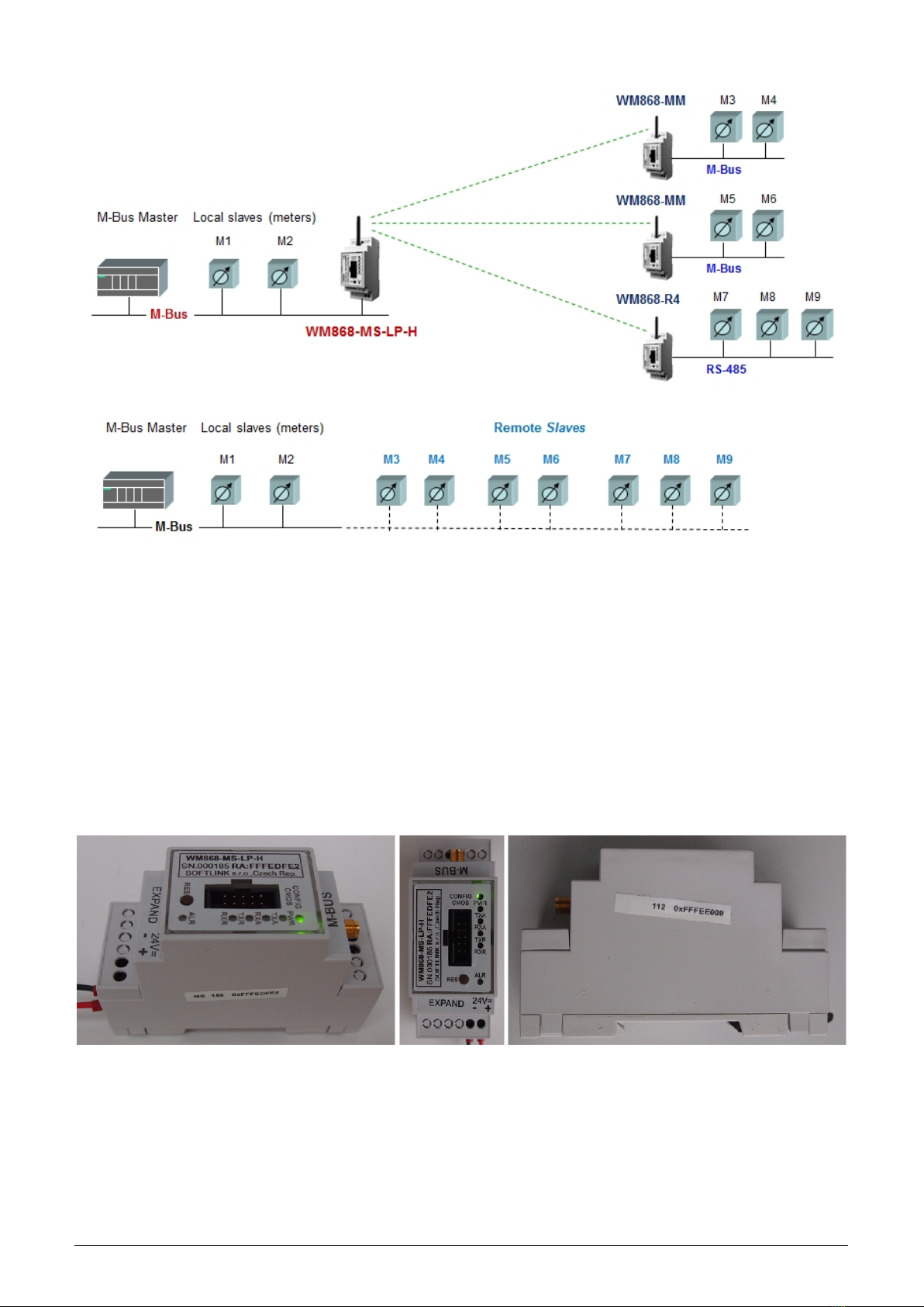
Figure 1: Principle of transparent data transfer in WACO RF-network
1.3 Hardware features and power supplying
The module is enclosed in a plastic casing adapted for mounting on a DIN-rail. The box has a standard ”circuit
breaker” profile and width of two standard DIN-modules. The module is equipped with a M-Bus data bus
screw-on terminal with two clamps.
The module needs an external power supply 24V DC. For connecting of the power supply there is a screw-on
terminal with marked voltage polarity. Power supplying must follow all the safety requirements according to the
appropriate standards. Maximum current consumption of the module (for voltage of 24 V) is up to 50 mA, the
module is protected on the power supply input by reversible fuse with release current of 300 mA.
The module cannot be used in exteriors without additional covering. External appearance of the WM868-MS-LP-H
module is shown in the Figure 2.
Figure 2: View of the WM868-MS-LP-H module
WM868-MS-LP-H 2

2 Technical parameters overview
Overview of WM868-MS-LP-H module technical parameters is shown in the Table1below.
Table 1: Overview of WM868-MS-LP-H module technical parameters
RF subsystem parameters
Frequency band 868,0 - 868,6 MHz
Modulation FSK
Number of channels 3
Bandwidth 200 kHz
Transmitting power 25 mW
Receiver sensitivity 106 dBm
Communication protocol WACO
Transmission speed 38400 Baud
Antenna connector SMA female
Antenna characteristic impedance 50 Ω
Configuration interface RS232
Transmission speed 19200 Baud
Operation mode asynchronous
Transmission parameters 8 data bits, 1 stop bit, none parity
Signal level TTL/CMOS
Data-bus interface
Interface type M-Bus Slave (two clamps)
Transmission speed 300 ÷9600 Baud
Operation mode asynchronous
Transmission parameters (default) 8 data bits, 1 stop bit, none parity
Signal level by EN1434-3, EN60870
Nominal current consumption 1,5 mA
Power supplying
External power supply 24 V ±10%
Input power 4 W
Weight and dimensions
Width 35 mm
Height 90 mm
Depth 58 mm
Weight cca 150 g
DIN casing size 2 modules
Storage and installation conditions
Installation environment (by ˇ
CSN 33 2000-3) normal AA6, AB4, A4
Operation temperature range (-20 ÷50) ◦C
Storage temperature range (0 ÷70) ◦C
Relative humidity 90 % (w/o condensation)
Degree of protection IP20
Signaling and control
Power signaling ”PWR” green LED
Signaling of RF transmission ”TXA” yellow LED
Signaling of RF reception ”RXA” yellow LED
Signaling of bus transmission l ”TXR” yellow LED
Signaling of bus reception ”RXR” yellow LED
Signaling of RF signal collision ”ALR” red LED
System restart button ”RES”
WM868-MS-LP-H 3

3 Configuration of the WM868-MS-LP-H module
Configuration parameters of the WM868-MS-LP-H module can be displayed and changed from the common com-
puter (PC) by one of these methods:
- with using of ”USB-CMOS” converter and configuration cable connected to the module
- wirelessly, with using of WM868-RFU radio-frequency communication gateway
Technique of interconnection of the module with configuration computer and general rules of configuration are
described in detail in the section 3.1 ”Configuration of the module with using of the configuration cable”. The
description and meaning of all configuration parameters that can be checked and changed by cable can be found in
the section 3.5 ”Setting of WM868-MS-LP-H parameters via configuration cable”. Description of interconnection
of the WM868-RFU RF-communication gateway with computer and general rules of configuration via radio are
described in the section 3.2 ”Configuration of the module via radio”. The description and meaning of the parameters
that can be changed via radio can be found in the section 3.6 ”Setting of WM868-MS-LP-H parameters via radio”.
3.1 Configuration of the module with using of the configuration cable
Configuration of the module can be performed by using of any PC with MS Windows or Linux operating systems
interconnected by configuration data cable. The module’s communication interface is of RS-232 (COM) type with
CMOS signal level. The ”CONFIG CMOS” configuration connector is placed on the module’s front panel.
3.1.1 Connecting of module to computer
Configuration can be performed by using of common USB port of the computer. For the interconnection with a
USB port of computer it is necessary to use an manufacturer’s original configuration cable with ”USB-CMOS”
converter (see Figure 4). This converter creates a virtual serial port through the USB interface and adapts voltage
levels of the module’s configuration port to the standard USB port of common PC. So as to be able to create a
virtual serial connection via USB interface, there must be a relevant driver installed in the computer operation
system. After the ”USB-CMOS” converter is connected to computer for the first time, operating system will find
and install appropriate generic driver of ”USB Serial Device” category automatically. After driver installation is
completed, the device will appear in the ”Ports (COM and LPT)” section of the ”Device Manger” window as ”USB
Serial Device (COMx)” (see figure 3).
Figure 3: Appearance of the USB-CMOS converter in Windows ”Device Manager”
As some of the older MS Windows versions do not support a generic driver for USB serial ports, the automatic
installation of the driver could fail (system reports ”Driver software installation failure”, or ”driver not found“).
In this case there is necessary to install the driver manually, following the steps in paragraph 3.3 ”Installation of
USB-CMOS converter driver”.
Insert USB-CMOS converter to the USB port of computer. Connect configuration cable to the ”CONFIG CMOS”
port on the module’s front panel. Thus, the computer is connected with the module and ready for performing any
changes in configuration (see figure 4”Configuration via USB port of computer”).
WM868-MS-LP-H 4

Figure 4: Configuration via USB port of computer
3.1.2 Using of ”PuTTy” freeware program for configuration
The module configuration can be done with using of any suitable program for the serial line communication. The
description bellow is relevant for the open-source software ”PuTTY” that is available for free on www.putty.org.
Figure 5: Terminal setting for serial line communication
”PuTTY” software runs after clicking on the downloaded file ”putty.exe“. There will open a window of the terminal
communication (see Figure 5). For switching the program into the serial line communication, choose ”Serial” option
of the connection type in the ”Session” tab.
Check (or set up) the communication speed (”Speed”) to 19200 bits/s and then enter into the ”Serial line“ tab the
number of the serial port that the system automatically assigned to the virtual port at the moment of interconnection
module to the computer. The number of the serial port can be found in OS Windows by using of ”Device Manager”
(Control Panel/System and Maintenance/Device manager) by clicking on ”Ports (COM a LPT)” where the numbers
of ports appear (e.g. ”COM23” - see figure 3).
Click on ”Open” button in ”PuTTY” program and open the terminal window. After pressing of ”ENTER” key
there will appear a command prompt ”sysmon” which announces that the module is ready to be configured (see
figure 6).
WM868-MS-LP-H 5

Figure 6: Open terminal window for module configuration via serial line
3.1.3 General rules for configuration of the module by configuration cable
Activate the terminal window for the configuration via the configuration cable according to the instructions above.
These general rules are valid for entering commands into the command line:
•the command must be entered only when a prompt for command appears in front of the cursor mark (colored
or flashing little square); the prompt is either ”sysmon” or ”mon” format (see figure 6);
•it is possible to enter only one command each time;
•the command could be entered in an alphanumeric character (or several characters);
•the command is sent to device by clicking on ”ENTER” key. After the command being carried out, the
prompt will appear again and it is ready for a new command to be entered. In case the command fails to
execute, there will appear an error report;
•check the execution of the command by displaying of the list of configuration parameters which appears by
entering ”show” or ”/” and pressing on ”ENTER” key;
•to display a summary of configuration commands and their parameters (”HELP”), enter ”?” (question mark),
or ”/?” and press ”ENTER” key;
•when entering characters, distinguish strictly the capital and small letters (according to the documentation
or ”HELP”);
•Do not enter other characters than those listed in ”HELP“ or in the documentation, otherwise you would
be risking the unwanted command enter that might be the same as the ones used for manufacturer settings,
diagnostics or service and repair.
3.2 Configuration of the module via radio
Remote configuration via radio signal is proceeded via special WACO radio messages (queries and commands) that
will query the module to get current settings of its individual parameters, or (in case of need) will send a command
to change these parameters.
It is possible to configure the module locally from the convenient spot within module radio range (for example
from PC with connected gateway WM868-RFU - see figure 7), or to configure the module remotely from a remote
computer via local gateway WM868-RFE (WACO Ethernet Gateway) or WM868-RFG (WACO GSM Gateway) as
depicted in the figure 8.
Figure 7: Principle of local configuration via radio
In both cases there must be direct radio visibility between the configured module and the communication gateway
– it is totally impossible to configure the WM868-SI2/SI2-H modules via repeater.
3.2.1 Using of ”RFAN 3.x” program for the module configuration via radio
The universal tool for the configuration of WACO family modules is ”WACO Radiofrequency Analyzer RFAN 3.x”
(hereinafter ”analyzer”) that can be used for setting up of all remotely configurable parameters of the module.
Analyzer is a computer program written in Java language, which can be installed to any common PC (desktop,
laptop, tablet...) with operating system with Java Virtual Machine support. Functionality of RFAN 3.x analyzer
WM868-MS-LP-H 6
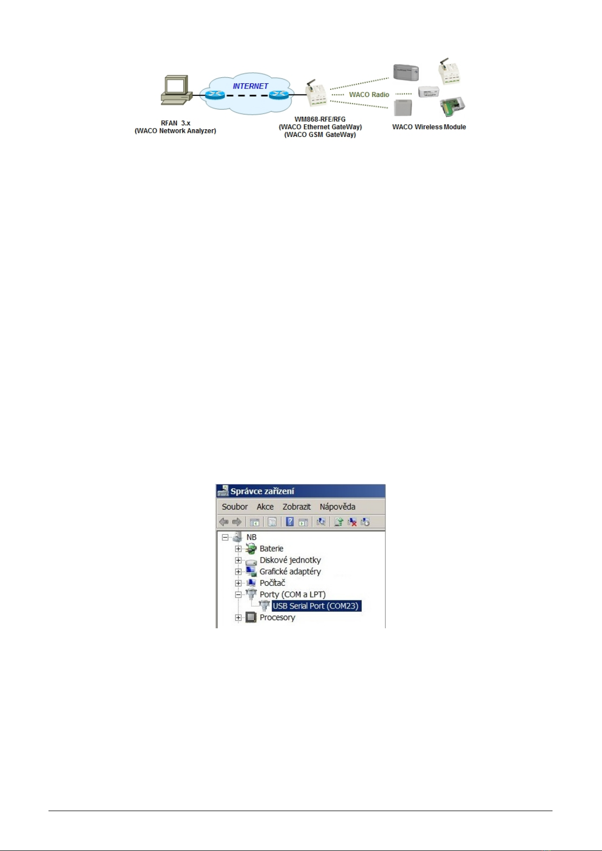
Figure 8: Principle of remote configuration via radio
is described in detail in the ”WACO RFAN 3.x – Software description and configuration” manual, where there are
also described in details the steps how to find out current setting of a particular parameter and how to change the
setting.
Purpose and importance of all configuration parameters is described in the next part of the document. Overview of
all parameters that can be configured via radio can be found in the section 3.6 ”Setting of module parameters via
radio”. General principles and technique of radio configuration are described in details in section 3.2.3 ”General
rules of configuration via radio”.
3.2.2 Connection of WACO communication GateWay to computer
WACO Communication Gateway is the device intended for communication among a WACO supported software
application (e.g. RFAN 3.x) and all subordinate elements of WACO wireless network. The GateWay can be
connected to the computer with the RFAN 3.x application directly (through a convenient port of PC) or indirectly
through the IP network. ”WACO USB GateWay” (with USB support) as well as ”WACO Ethernet GateWay” (with
etrhernet support) can be connected directly, while ”WACO Ethernet GateWay”, and ”WACO GSM GateWay”
can be connected indirectly, what means that the GateWay is not connected to the computer with analyzer, but it
is connected to the remote Ethernet/IP port of the IP-network (Internet) anywhere over the world provided that
there is an IP-connection between the computer and the GateWay (see figure 8).
Connect WM868-RFU (WACO USB GateWay) to the USB port of computer with RFAN 3.x program. The module
is powered from the USB port of computer, so it automatically goes ”on” and three virtual serial ports are activated:
one for data connection, one for configuration and one for possible firmware upgrade. The device appears in the
”Other devices” section of the ”Device manager” window and its virtual serial ports appear in the ”Ports (COM
and LPT)” section as depicted in the figure 9.
Figure 9: Appearance of WACO USB GateWay in the MS Windows ”Device Manager”
If there is no appropriate driver with support of multiple virtual serial ports over USB installed in the computer, it
is not possible to select serial port in RFAN 3.x setting (no serial port is available for choice). In this case the virtual
serial ports appear in the ”Other devices” section of ”Device Manager” and it is necessary to install appropriate
driver according to the instructions stated in part 3.4””USB GateWay and USB-IRDA driver installation”.
3.2.3 General rules for configuration via radio
RFAN 3.x Analyzer enables remote configuration of WACO radio devices. This function is accessible in folder
”Remote Config”. The principles of the configuration tools are following:
- select the device to be configured (or read current configuration)
WM868-MS-LP-H 7
- select variable that should be changed (or read)
- launch function ”GET” for reading current value, or ”SET” for changing of value or ”WALK” for reading of
all values
When performing of configuration (i. e. making changes or just reading of current settings) keep these general rules:
1. the configuration cannot be made in bulk, there must be always only one device chosen that will be configured;
2. each single variable is set up/queried by a single command/query;
3. there is a possibility to define more configured/queried variables within the tool and run their configura-
tion/query by one click as a sequence, nevertheless, the configuration/querying of each variable is processed
individually, one after another, in the order in which the sequence was set up;
4. in case the ”WALK” command for querying the current status of all module’s variables is used, the analyzer
starts dispatching queries that will ask the individual variables step by step;
5. when a ”SET” command was sent to device, the device will proceed the command (or not – see rule 6. and
7.) and turns back a value that is really valid after the command execution;
6. if a ”SET” command was sent to a variable, that is of ”Read Only” character (for example type of the device,
or serial number), then the device will not process the command and turns back current value of the variable;
7. if a ”SET” command contains such value that is out of the defined range of values of the variable, or that has
no sense, then the device either not process the command or change the variable to closest possible value. In
any case, the device will send back the value which is really set after proceeding the command;
8. if a ”GET”/”SET” command contains variable that is not implemented in the particular device (the device
”doesn’t recognize” the variable), then the device turns back ”null” value which appears in the analyzer as
not accomplished command/query.
3.2.4 Remote configuration with using of RFAN 3.x Analyzer in steps
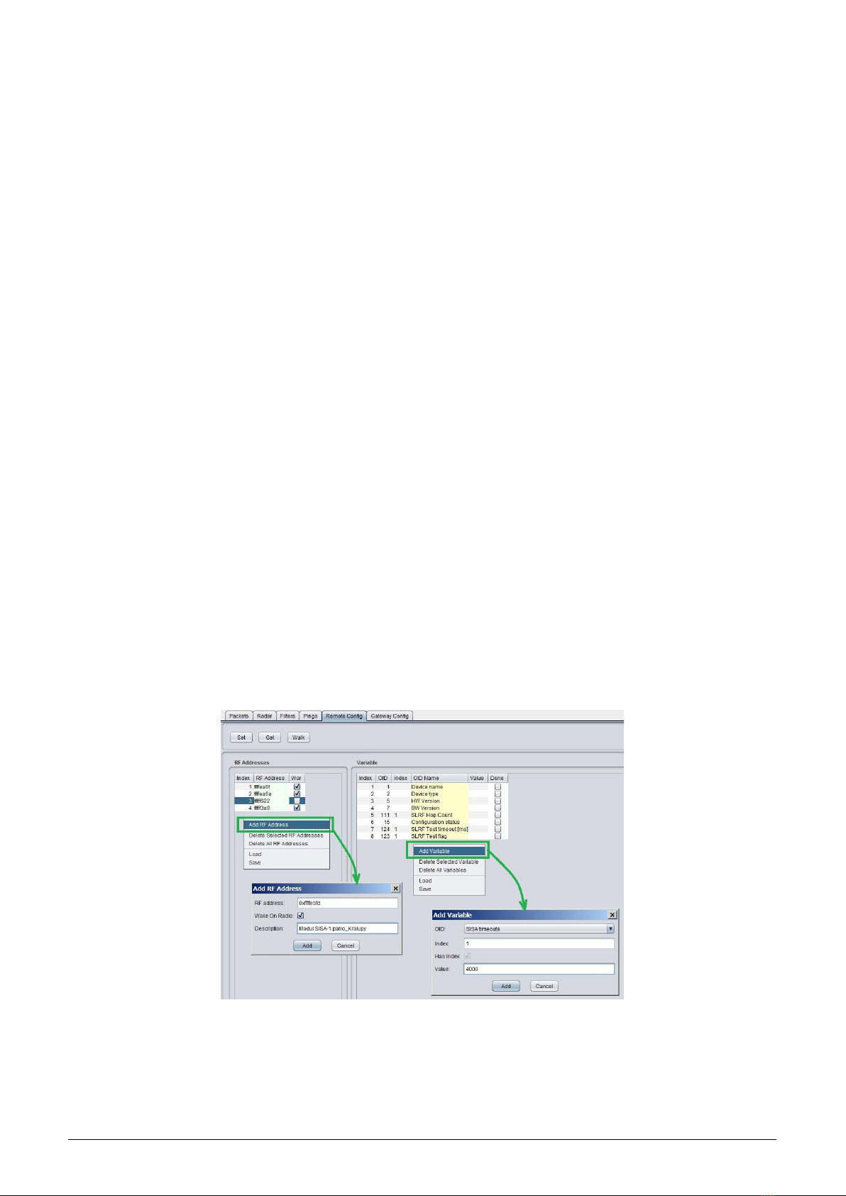
The configuration could be performed in ”Remote configuration” mode (fold ”Remote Config”). Add the device
that should be configured into the left section of the screen by using of ”Add RF Address” option of the section
context menu (displayed by right-click). The new ”Add RF Address” window (form) will open, where there it is
necessary to fill in:
- fill device RF address in hexadecimal format marked ”0x” (for example ”0xffffef6d”)
- tick the ”Wake On Radio” option for battery powered modules
- write any description into the ”Description” field for better module recognition
- by clicking to ”Add” button add the device into the configuration list.
Entering of a device into the ”RF Address” window is depicted in the left part of the figure 10.
Figure 10: Entering of devices and variables into the remote configuration window
Create the sequence of variables that should be configured (query or set) by clicking on ”Add Variable” option in
the right section context menu. The new ”Add Variable” window (form) will open, where there it is necessary to
edit following fields:
•into OID field (Object ID) select a name of variable that should be added in the sequence
WM868-MS-LP-H 8

•in case the variable has an index, put the index number in (information box ”Has Index“ is ticked and ”Index“
box is editable);
•set up required value of the variable into the ”Value“ field. If the variable will be just read (checked its current
value), leave the field blank. Those variables, that have ”Read only“ status (invariable constants, measured
values) will have the ”Value” box uneditable;
•by clicking on ”Add“ button add a variable to the sequence of variables used for configuration.
Entering of a variable into the ”Variables” window is depicted in the right part of the figure 10.
Command GET (reading the current variable value), SET (setting up the required variable value), or WALK
(reading the current status of all variables) will be done only for one chosen device from the list of devices in ”RF
Address“ tab. Run the required command by clicking on relevant button in the top of the screen. After the click,
there will appear an information window in which a progress of getting/setting process of will be displayed. As the
individual settings are performed, the ”tick” symbols in the ”Done” box appear item-by-item. The ”Getting/Setting”
window will disappear after the all commands of the sequence are being accomplished, or after the expiration of
the preset time limit (TimeOut). The current variable values are listed in the field ”Value” in the relevant row.
Figure 11: Progress of getting values of preselected variables of the module by using of ”GET” command
To avoid serious mistakes that can bring the module into paralyzed condition, numb for further communication, it
is necessary to know the meaning of all modified variables of the device, including their mutual relations.
Example: If value of ”SLRF Test Flag” variable is set to ”1”, the module will be preset to send test messages in
period which is set up by variable ”SLRF Test Timeout [ms]”. In this case the period is just 1 millisecond. The
trouble will occur if the test broadcasting would be switch on. It is necessary to set some reasonable period (e.g.
5 second) first and just then switch test broadcasting ”on”, otherwise the module would broadcast permanently and
never be able to receive any other command.
When configuring battery powered modules, always use the ”Wake-On-Radio” (WOR) function. The function
enables to ”wake up” the module with a special ”waking” radio signal from ”hibernation” mode (that means the
mode in which the module is almost permanently) to the mode of active signal reception. Keep in mind that by
”waking up” of the particular required module the other modules, that are placed within the GateWay current
radio range, will also be activated. Excessive activating of the module can cause the reduction of its battery life. To
avoid the excessive ”waking” of many modules around the GateWay it is recommended to follow these instructions:
- do not change the parameters if it is not necessary for the module’s functionality; - consider the succession
of the configuration commands (or prepare them as a ”template”); - do not use command ”WALK” if not
necessary - (reading of all module variables); - find suitable place for the configuration, that is in a good reach
of configured device.
We also recommend keeping the modules in closed boxes, shielded with aluminum foil (or in metal boxes) so the
modules are protected from the excessive ”waking up” and their batteries won’t be damaged. When you do the
preliminary configuration before mounting, always take out from the shielded box only the necessary number of
modules. After their configuration, the modules should be placed back in the shielded box.
3.3 USB-CMOS converter driver installation
If the computer operation system failed in automatic installing of the driver for the ”USB-CMOS”, it is necessary
to install the driver manually. The relevant current driver can be found on a chip manufacturer’s (FTDI) webpages,
namely in the ”VCP Drivers“ (Virtual COM Ports) section.
www.ftdichip.com/Drivers/VCP.htm
In the ”Currently Supported VCP Drivers” table find a link to a driver relevant to your operating system. To
download the file, click on a link in the table. After downloading the file (in .ZIP format) into any directory in
your computer, unzip the file. It will create a new folder (directory) with a set of files (e.g. ”CDM 2.08.24 WHQL
Certified”).
WM868-MS-LP-H 9
Connect the converter ”USB-CMOS“ to your computer and open a ”Device Manager” tool. The converter with the
disabled driver will be displayed in the top right corner of the window as ”Other Devices” (see figure 13 left).
Figure 12: Appearance of converter without driver in the Windows ”Device Manager” table
Click by right mouse button on ”USB Serial Port” and choose ”Update Driver Software” option in the context menu.
Choose ”Find Driver in this computer” option in the ”Update Driver Software” window. Use ”Browse” button to
set up the path to the driver‘s folder (directory) and then click on the ”Next” button. The driver installation process
will launch. After the driver installation is completed, the standard ”Installation Completed” message will appear.
After the installation the converter will appear in the ”Ports (COM and LPT)” section of the ”Device Manager”
window (see figure 13 right).
3.4 ”USB GateWay” and ”USB-IRDA” driver installation
The driver ”ugw3.inf” intended for support of multiple virtual serial ports through the USB interface of a computer
is a part of delivered installation pack. If your version of MS Windows operating system failed in automatic
installation of a driver for connected ”USB GateWay” or ”USB-IRDA” device, make an installation of ”ugw3.inf”
driver manually.
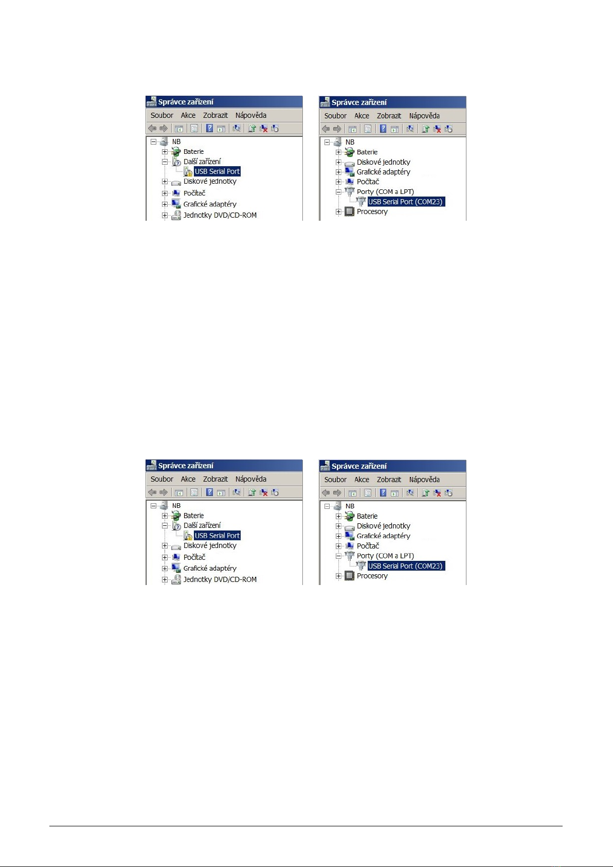
Connect the device to computer and open a window of ”Device Manager” tool. The device appears in the ”Other
device” section in upper part of the window as ”USB Serial port” device (see figure 13 left).
Figure 13: Displaying of the device without driver in ”Device Manager” window
By right-clicking to ”USB Serial port” open the context menu and choose ”Update driver software” item. Click on
”Find driver in this computer” in the opened window. Click to ”Select driver from the list” and ”Next” in next
window. After a new ”Select device type from the following list” window appears, select ”Ports (CPM & LPT)” in
the window and click to ”Next” button (see figure 14 left). Choose ”From disc” in the next ”Choose driver which
you want to install” window ( figure 14 right).
After that a new ”Find file” window appears. Set the folder with driver file in the ”Browse” tool, select ”ugw3.inf”
file name that will appear in the window and click to ”Open” button (see figure 15 left). A new ”Choose driver
to be installed for the hardware” window will appear, select ”RFU Gateway Serial port” item and click to ”Next”
button (see figure 15 right).
WM868-MS-LP-H 10
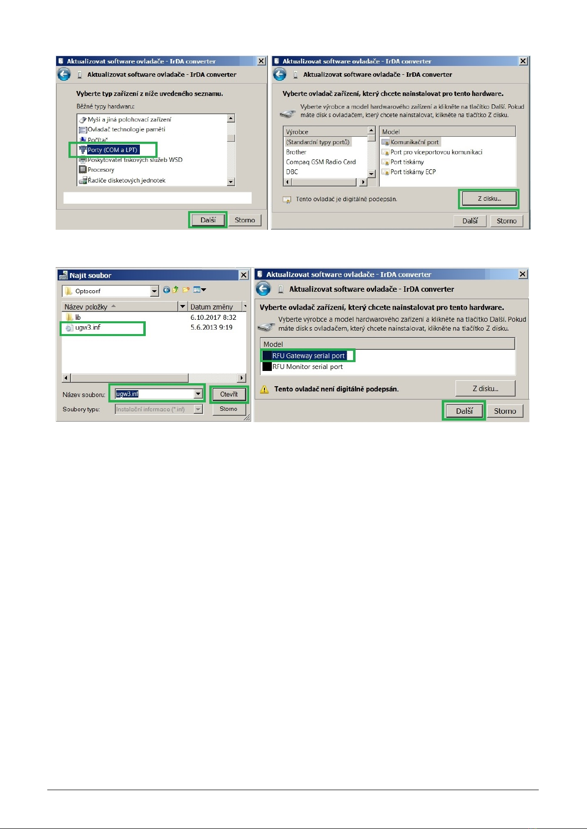
Figure 14: Manual selection of the driver file from a folder
Figure 15: USB driver installation
A new ”Driver software installation” window will appear with standard red ”unknown driver producer” Windows
system warning. Click to ”Install the software anyway” option and the installation process will launch (*). After
the process is completed the system shows positive message ”The driver was successfully installed” (or similar).
The device will move to the ”Ports (COM & LPT)” section of the ”Device Manager” window (see figure 13 right).
(*) If installing the driver into the Windows 8 or Windows 10 OS computer, it could be a security problem with
the installation because the driver doesn’t have a digital signature (”unsigned driver“). In this case follow the
instructions below.
3.4.1 How to disable driver signature enforcement in Windows 8 system
Enforcement of signed driver installation in Windows 8 can be disabled by following procedure:
•by pressing the ”Windows + R” keys open the ”Run” window;
•write a restart command ”shutdown.exe /r /o /f /t 00” into the ”Open” editable field;
•choose ”Troubleshoot” option in the ”Choose an option” window that will pop-up;
•choose ”Advanced options” in opened ”Troubleshoot” window;
•choose ”Windows Startup Settings” in opened ”Advanced options” window and run ”Restart”;
•during the system restart process a window ”Advanced Boot Options” appears, choose ”Disable Driver Sig-
nature Enforcement” option in this window;
•after launching the system install the driver according the above mentioned instructions.
Deactivation of the enforcement of signed driver function of the Windows 8 operating system is functional only
until the next restart of the system.
WM868-MS-LP-H 11

3.4.2 How to disable driver signature enforcement in Windows 10 system
Enforcement of signed driver installation in Windows 10 can be switched-off by following procedure:
•click to ”Windows” icon in left the bottom left corner of the screen and choose ”Settings” icon;
•select ”Update and security” in ”Settings” window;
•select ”Recovery” in next window’;
•select ”Advanced startup” section in ”Recovery” window and click to ”Restart” button in the section;
•in a few seconds the new ”Choose an option” screen appears; select ”Troubleshoot” option;
•in next steps select ”Advanced options” and ”Startup repair” options and click to ”Restart” button;
•in this step an instruction for entering of ”BitLocker” recovery key could appear (depends on the system
settings). This is a 64-character access key for data section of the user that can be used in case of loss of OS
Windows password. The key can be found in the ”Microsoft Account Settings” page, that can be displayed by
clicking to ”Windows” icon and ”User” item of main Windows menu. To get to the account it is necessary to
click to ”Change account setting” and ”Manage my Microsoft account” and log into the account by using of
Microsoft user login/password. Select ”Device” in main menu of the user account page and click to ”Obtain
BitLocker recovery key” in ”Desktop” section and ”Bitlocker” subsection. The new screen with recovery keys
will open. Copy down the key that is valid for the required unit (according to the required unit identifier);
•after entering of the key the new screen with startup options will appear, select ”Disable Driver Signature
Enforcement” option from the list. The selection can be done with using of F1 - F10 keys, for selected option
with order number ”7” press key ”F7”;
•after OS Windows restart perform the driver installation according to the above described procedure.
Deactivation of the enforcement of signed driver function of the Windows 10 operating system is functional only
until the next restart of the system.
3.4.3 Support of older OS Windows versions and OS Linux support
Earlier MS Windows versions (Vista, Windows XP and older ones) do not support sufficiently the installation of
multiple virtual serial ports onto one physical USB port and the current versions of ”USB GateWay” and ”USB-
IRDA” devices cannot be connected to the computers with these operating systems.
There is no need to install any drivers with serial port support to the computer with Linux OS as the Linux system
will automatically use its own generic drivers.
WM868-MS-LP-H 12

3.5 Setting of WM868-MS-LP-H module parameters by configuration cable
In following part of the document there is a description of these parameters of the WM868-MS-LP-H module, that
can be displayed and examined from PC connected to the module by configuration cable. Some of the parameters
can be changed by configuration commands entered ”from the console” as described in paragraph 3.1.
3.5.1 List of WM868-MS-LP-H module configuration parameters and commands
List of all configuration parameters of the module can be displayed by entering of ”/“ (slash) command and pressing
of ”ENTER” key. The following list of parameters will display in the terminal window:
sysmon>/
CONFIGURATION: OK
Address: 0xFFFEDFE2
Master: 0xFFFFFA39
Alarm: 0xFFFFFA39
Group: 0
Flags: C
PA table: C2
Channel: 0
Timeslot: 20 ms
# of timeslots: 5
Hop Count: 3
Test timeout: 1000 ms
Baud: 9600 8N1
Interbyte timeout: 50 ms
TX On timeout: 200 usec.
TX Off timeout: 500 usec.
Run test: 0
DEBUG: 0
sysmon>
List of all configuration commands (”HELP”) can be displayed by entering of ”/?” command into the command
line and pressing of ”ENTER” key. The following list of commands will display in the terminal window:
sysmon>/?
/W - save configuration
/# - clear configuration
/m addr - set Master’s address
/ma addr - set Alarm address
/g group - set group (multicast address)
/h count - set hop count
/f [+-][emCwzG] - set flags (e-range extender, m-master, C-Carrier Detect
w-WOR mode, z-Zone Extender Algorithm, G- high gain)
/c number - set RF channel 0..2
/l slots - set # of timeslots in RF network
/t timeout - set timeslot timeout in ms
/P patable - set PA table value
/T timeout - set test timeout in ms
/E flag - run test (0-Off,1-On)
/D flag - debug (0-Off,1-On)
/b baud set baud rate (300..115200)
/p [n|e|o] set parity (none,even,odd)
/d number set data bits (7,8)
/s number set stop bits (1,2)
/i timeout set interbyte timeout in ms
/O timeout set TX On timeout in usec.
/F timeout set TX Off timeout in usec.
/x - RESET
sysmon>
WM868-MS-LP-H 13

Overview of configuration parameters with short description of their meaning can be also found in table 2on the
page 21.
The detailed description of individual parameters and their setting possibilities can be found in the following part
of chapter 3.5.
3.5.2 ”Configuration” group of commands for writing of configuration and reset
The module contains two sets of configuration: operating configuration and saved configuration. At the start of
the system the module copies saved configuration into the operating configuration, with which continues to work.
If the user changes configuration parameters, it does so only in operating configuration.
Current status of storing of configuration parameters can be displayed in the list of all configuration parameters as
”CONFIGURATION” item:
CONFIGURATION: OK
Information ”OK” means, that the operating configuration is stored (it is identical with stored configuration)
Information ”NOT WRITTEN” means, that the operating configuration is different from the configuration stored
in Flash.
Configuration can be saved to Flash memory by using of ”/W” command. Example:
sysmon>/W
If the current operating configuration was not stored to FLASH memory, the module returns to the saved config-
uration after reset. If the parameter should be changed only temporarily (for example switch-on ”test” function
during diagnostics), it is not necessary to save operating configuration into FLASH memory (after diagnostics the
function will be switched-off anyway). If the parameter should be changed permanently, there is necessary to save
the configuration to FLASH memory.
Configuration can be erased from the Flash memory by using of ”/#” command. Example:
sysmon>#
WARNING! This command is recommended to use only by users with good knowledge of the system, or after
consultation with the manufacturer.
The module reset can be performed by using of ”/x” command. Example:
sysmon>/x
After entering the command the module goes to software restart.
Change of some configuration parameters has an effect only after module reset (e.g. retuning of module radio
by changing of ”SLRF Channel” parameter). In this case it is recommended to create a configuration sequence
containing commands for change of parameter, saving the change to Flash, as well as command for performing of
module reset (..and exactly in this order).
3.5.3 Commands for settings of radio-frequency subsystem
This group of commands enables setting of transmitting, receiving, repeating and addressing system. There are
following commands:
/c number frequency channel setting (SLRF Channel)
/h count maximum number of re-transmissions (SLRF Hop Count)
/f[+-] flags repeating mode setting (SLRF Repeater flag)
/F[+-] flags transceiver mode setting (RF Driver flags)
/X time receiving time interval (not used)
Names of parameters that are configured by individual commands are stated in the brackets.
The ”SLRF Channel” parameter is a number of module frequency channel. RF modules of WACO commu-
nication system can be tuned to any of three separate frequency channels that don’t influence each other.
WM868-MS-LP-H 14

Frequency channel of the module can be set by ”/c [number]” command, where value 0, 1, or 2 means number
of frequency channel to be tuned. Change of frequency channel is effective only after module reset. Example of
sequence of commands for module setting to the frequency channel ”1”:
sysmon>/c 1
sysmon>/W
sysmon>/x
The ”SLRF Hop Count” parameter is a maximum number of re-transmissions of the messages, broadcasted by
the module. If, as an example, the parameter is set to value ”3”, each message originated by the module will be
discarded after three re-transmissions (it is repeated no more than 3 times). This mechanism prevents the system
from uncontrolled circulation of the message within the network. It is recommended to set the parameter to ”n”
or n+1” value, where ”n” is the least number of re-transmissions which is necessary to get the massage to its
destination. If the ”SLRF Hop Count” value is too low, the message is discarded before reaching of its destination.
If the ”SLRF Hop Count” value is too high, capacity of the network is loaded by useless repeating of the messages.
The ”SLRF Hop Count” parameter can be set by ”/h [number]” command, where the value from 0 - 15 interval
means the maximum number of re-transmissions (”hops”) of the messages, broadcasted by the module. Example
of command for setting of ”SLRF Hop Count” parameter to value of 3 ”hops”:
sysmon>/h 3
The ”SLRF Repeater flags” parameter is intended for setting of repeating (re-transmission) mode. Repeating
mode can be set by using of ”/f[+-] [flags]” command, where the required mode is chosen by entering of one of
following pre-defined symbols (”flags”):
- value ” ” (without flag) - none of below mentioned functions is involved
- value ”e” - setting of basic repeating mode (without back transfer suppression)
- hodnota ”Z” - setting of advanced repeating mode with back transfer suppression (AZRA)
- value ”m” - designating of the module as a ”Master” of virtual bus
Example of command for setting of the module as a repeater with ”Advanced repeating mode AZRA” (recommended
setting):
sysmon>/f e Z
The ”RF Driver flags” parameter is intended for setting of module transceiver mode. The mode can be set by
using of ”/F[+-] [flags]” command, where the required transceiver mode is chosen by entering of one or more of
following pre-defined symbols (”flags”):
- value ”C” - full anti-collision protection (carrier and frame transmission detect) enabled
- value ”R” - limited anti-collision protection (carrier detect) enabled
- hodnota ”W” -”Wake On Radio” (WOR) function of the receiver enabled
- hodnota ”G” -”High Gain” function enabled (it has no effect for WM868-MS-LP-H module)
Important notice:
The ”C” and ”R” functions are alternative options and their setting works as a change-over switch (when one
of them is enabled, second one is automatically switched off). The ”W” and ”G” functions are independent. Their
flags can be added or removed individually by using of +/- symbol before the flag.
Example of command for common setting of ”Full anti-collision protection” and ”Wake On Radio” functions and
corresponding record in the module configuration summary:
RF Driver flags: R
sysmon>/F C +W
RF Driver flags: CW
Example of command for switching of protection to ”Limited anti-collision protection” mode and corresponding
record in the module configuration summary:
RF Driver flags: CW
sysmon>/F R
RF Driver flags: RW
WM868-MS-LP-H 15

As seen in the example, by enabling of ”R” function the original ”C” function was automatically switched off and
it had no influence on the ”W” function.
Example of disabling of ”W” function and corresponding record in the module configuration summary:
RF Driver flags: RW
sysmon>/F -W
RF Driver flags: R
As seen in the example, disabling of ”W” function had no influence on the ”R” function.
Example of command for common setting of ”W” and ”G” functions and corresponding record in the module
configuration summary:
RF Driver flags: R
sysmon>/F +W +G
RF Driver flags: RWG
Example of command for switching of anti-collision protection to ”C” mode together with disabling of ”G” function
and corresponding record in the module configuration summary:
RF Driver flags: RWG
sysmon>/F C -G
RF Driver flags: CW
When the ”Full anti-collision protection” function is switched on, the module opens its receiver for an instant
before broadcasting and ”listens” whether the frequency channel is clear. If a carrier frequency is detected or
transmission of a frame is underway, the module postpones broadcasting of the message for a moment and then tries
again. This procedure protects transmission of the message from interference with disturbing signal on the same
frequency as well as from collision with broadcasting of other modules.
When the ”Limited anti-collision protection” function is switched on, the module goes to transmission if there
is no other frame underway (but, unlike the full protection, detection of carrier is not performed). This procedure
does not protect broadcasting against disturbing signal, but protects transmission of the message from collision with
broadcasting of other modules. This setting is recommended in this case when the module works in the environment
with permanent disturbance of carrier frequency and it has no sense to waste time (and battery power) by waiting
for clear channel.
When the ”Wake On Radio” (WOR) function is enabled, the module can be anytime remotely activated from
hibernated state. As the WM868-MS-LP-H module is permanently active, this function has no importance and
should be switched off.
The ”/X” command is intended for setting of ”receiving time interval”, what is the interval immediately after
sending a message in which the module’s receiver is active. The interval is set in ”system units” of 50 ms (20 units
= 1 second). As the WM868-MS-LP-H module’s receiver is permanently active, this function has no importance.
Important note! Even the possibilities of transceiver settings are identical for all modifications of the WM868-MS-
LP-H module, older versions of the module can have a different way of choosing of the required transceiver
mode. In this manner the switching of transceiver mode should be performed by using of ”/f[+-]” command (the
same as for setting of repeating mode), where the set of flags is supplemented with following flags for seting of
transceiver mode:
- flag ”C” for full anti-collision protection setting (Carrier Detect)
- falg ”w” for enabling of ”Wake On Radio” (WOR) function
- flag ”G” for switching of ”High Gain” function (not used)
Switching to limited anti-collision protection mode can be performed by removal of ”C” flag from the configuration.
Switching from factory preset full anti-collision protection mode to the limited anti-collision protection mode can
be performed this way:
SLRF flags: eCz
sysmon>//f -C
... SLRF flags: ez
Manner of transceiver settings control of the particular device is obvious from the summary of configuration com-
mands (”HELP”), that can be displayed by ”/?“ command.
WM868-MS-LP-H 16

3.5.4 Commands for setting of addressing in virtual bus
The ”Virtual BUS” application of the WACO communication system (port ”32”) enables organizing of modules of
WACO WM868 series into the wireless ”virtual bus”, where the communication is going on in the ”master-slave”
mode. All the modules in the virtual bus must have preset the same group address (”SLRF Group Address”).
One of the modules, that is designated as ”Master” of the bus, broadcasts messages of ”query” type to all other
modules with using of group address of the bus, and all modules (apart from the master) send back their messages
of ”answer” type to the master’s individual address. The principle of addressing in the ”Virtual BUS” application
is depicted in the figure 16.
Figure 16: Principle of addressing in the WACO ”Virtual BUS” application
Addressing of virtual bus can be configured with using of following commands:
/f[+-] [m] designating of virtual bus ”master’ - see paragraph 3.5.3
/g group setting of the module group address (SLRF Group Address)
/m addr setting of superordinate master address (Master’s address)
/ma addr setting of alarm messages address (Alarm address)
The module can be designated as a ”master” of virtual bus by using of ”/f” command with ”m” flag as
described in the previous paragraph 3.5.3 ”Commands for settings of radio-frequency subsystem”.
Setting of module group address (”SLRF Group Address”) can be performed by using of ”/g [number]”
command, where the number from 0 - 65535 interval is the module group address. Example of setting of the group
address to the ”21” value and corresponding record in the module configuration summary:
sysmon>/g 21
...
group: 21
Setting of superordinate master address (Master’s address) can be performed by using of ”/m [RF address]”
command, where ”RF address” is the RF address of the superordinate device in hexadecimal format. Example of
setting of ”Master’s address” to the ”FFFE52B4” value and corresponding record in the module configuration
summary:
sysmon>/m 0xfffe52b4
...
Master: 0xFFFE52B4
By using of ”/ma” command there is possible to preset similarly RF address of the network element (module),
that is responsible for collecting of alarm type messages. The module will send all alarm messages to the preset
WM868-MS-LP-H 17
This manual suits for next models
1
Table of contents
Other SOFTLINK Conference System manuals


Popular Conference System manuals by other brands


Altwork
Altwork TruVue Assembly and Use

Shure
Shure MXA902 manual

Eaton
Eaton xComfort CCIA-02/0 Series Assembly instructions

RADVision
RADVision Scopia XT5000 Series Quick setup guide

Grandstream Networks
Grandstream Networks GVC3212 Quick installation guide

Yealink
Yealink MeetingSpace VC500 quick start guide


