VTEL IPanel 2600 User manual

VTEL IPanel
VCS 5.0
User Guide
IPanel2600
IPanel3200
IPanel4200
IPanel3700

Initial Setup
IPanel 2600/3200
Please verify the following items are included with your shipment; camera with
mounting bracket, camera power supply, wireless keyboard, PC power supply,
DVD player power supply, panel IR remote, and software (including Windows XP
Pro).
A. Remove camera and
camera mounting plate from the
camera box (located in the
accessories box).
D. Connect the two cables (top of the LCD monitor) to
the camera --Yellow to composite, black to RS-232.
Make sure the camera power supply is connected to
camera and AC outlet.
All camera cables must be connected before
powering on the computer.
C. Use two screws to mount camera
bracket and camera to the mounting plate
holding the PC. Be careful not to over
tighten the screws.
Align the camera bracket with the front
of the monitor and stick it down with the
double sided tape.
B. Using a Philips screwdriver remove
the large silver screw from the bottom of
the camera and use it to mount the
camera mounting plate to the camera. Be
careful not to over tighten the screw.
Note: The L-shaped part of the mounting
plate (containing two small holes) should
face toward the back of the camera.
A. Connect the power supply
adapter-- a transformer (“brick”)
with a large 4-prong plug on one
end to the computer’s power
receptacle located on the bottom
left side of the computer. The
power supply adapter is found in
the accessory box.
B. Connect an RJ45 cable from your Internet or
LAN (local area network) connection to the
bottom of the computer in either RJ45 port.
1. Camera mounting
2. Power and network
C. Check all cable to ensure none came loose
during shipping.
+ +

D. On the back of the panel ensure the power
cable is connected and the rocker switch is on
E. Configure your External IP network using the
Network Configuration Guide in Section 6.
F. The set up is complete. You should not have to
do this again unless the system is moved to a new
location.
Down Up
Rocker Switch
ON position.
2. Power and network
(continued)
A. Power on the system using the power
button on the top of the computer and the
power button on the front of the monitor (all buttons are
either on the lower right front or lower right under the
edge of the panel).
B. The system will start up like any other Windows
XP computer going through familiar screens.
C. This computer screen will fill the panel’s display
3. Starting up the system
D. Double click on the red “V ball”
(“Start VTEL VCS” shortcut)
in the upper left corner. This launches the
videoconferencing software.
E. After a brief loading process, a large
VTEL “V ball” appears on the lower right
of the screen. This says that the video-
conferencing software is loaded.
Plus
The one button user controls on the wireless
keyboard are also now active.
VC PC TVPC VC
Note: if you do not see the usual Windows XP screens during start up
go to section 7.

VC PC TVPC VC
F6 F7 F8 F9
4. System modes
The IPanel has four main modes of operation.
You can toggle from one mode to another with one
button push using the four function keys highlighted
to the right. Note: these speed function keys only
operate when the VTEL VCS software is running
(see step 3.D and 3.E).
VC PC TVPC VC
Videoconferencing
Normal operation
for videoconference-
PC information on
left, video on right
Videoconferencing
Select VC to see full
screen of far site in
videoconference
Videoconferencing
or
Local PC
Presentation
Select PC to see full
screen of received PC
data in videoconference.
Select PC to see full size
presentation locally when
not in a videoconference
TV viewing
Select TV to see full
screen of cable TV
programs (includes
HDTV tuner)
5. Videoconferencing
Notes: (1) changing modes may take about
10 seconds. The flat panel is going through
a series of commands to set up the correct
display. (2) for PC or VC modes, if you can’t
see mouse cursor roll it over to left or right.
Note: The keyboard mouse works normally as a
PC mouse when the cursor is in the PC area…
and the keyboard mouse works as a videoconferencing
controller when the cursor is in the videoconferencing area.
B. Move the cursor to the right hand section (it will turn blue)
C. Right-click and the videoconferencing menu appears:
PC VC
A. Assuming you are starting from step 3E,
press PC/VC button (F6)
The screen at right will appear.
The left half is your local PC.
The right half is the videoconferencing section.
Place a Call
Audio Mute
Video Mute
Volume Control
Local Video
My IP Address
Exit VTEL Now
Cancel

Hand Dialer
Address Book
Speed Dial Keys
1. Call Rate
192 or 256 is a good
rate for the Internet
2. IP Address
Enter the IP address
you are calling
3. Click “Dial”
Hand Dialer – for ad-hoc connections
• Use this 3-step process when you just want to
connect to another site not in the address book.
• Call yourself in loop back by dialing your own IP
address to test that your system is working OK.
Address Book– for routine connections
• From list -- Use your cursor to highlight in blue
the site and then “left double click”.
• Speed Dial – Place the cursor over the speed dial
key and “left click”
• Put any site on a Speed Dial key by highlighting
the horizontal entry and drag and dropping it onto a
key.
• To add a site -- Right click in the “address book”
(white) portion and bring up menu with “add” at the
top. This is how to add sites to your address book.
5A. Videoconferencing Menu – Placing a call
Managing the address book
Place a Call
Audio Mute
Video Mute
Volume Control
Local Video
My IP Address
Exit VTEL Now
Cancel
Muting -- On Master Menu click:
• Audio Mute so far site cannot hear you
• Video Mute so far site cannot see you
• Undo mute – click on the mute line on
Master Menu again or,
• Click on the ICON displayed on your VC
screen.
An ICON appears on
your VC screen showing
status of audio and video mute
Volume: put your cursor where you
want the volume to go and left click.
Slide bar appears on PC side of screen
5B. Videoconferencing Menu
Use tabs to toggle
between hand dialer
and address book

+
-
Zoom
In
Zoom
Out
Remote Camera
pan
left/right/up/down
Cursor is small and white when
moved into left (PC) zone
Cursor is big and blue when
moved into right (VC) zone
5C. Camera controls using the keyboard mouse
Cursor is big and yellow when
moved into PIP window (PIP) zone
When in PIP zone the cursor controls
your local camera in the same way the
blue cursor controls the far camera
Left-click (and hold) to
move cameras
Using the mouse to control cameras is very natural … just
point where you want the camera to go.
Hang Up
Address Book
Audio Mute
Video Mute
Volume Control
Send PC
Local Video
My IP Address
Cancel
Left-click on “My IP Address”. This is the number that
other people should call to reach this system. It’s like a
phone number.
The IP address appears on the top of the PC (left)
screen in PC/VC mode. If you are in VC mode (far site
video picture only) the IP address will not appear.
5D. Videoconferencing Menu – Local IP address
Note: VCS 5.0 only detects the user’s IP address when it
launches. If you change your IP while VCS 5.0 is running
it will not know about it and your calls won’t work. To
remedy this problem, just Exit VCS (by selecting Exit
VTEL Now), and then launch VCS 5.0 again.

Show Local Video
Hide Local Video
Dock/Undock PIP
Your local
picture
(undocked)
size
move
Shows your video in PIP window
Removes local video (PIP)
• Undock: makes local video into
PC-style window. You can resize
and move anywhere
• Dock: removes top blue bar and
“docks” PIP window where you
last put it
Hang Up
Address Book
Audio Mute
Video Mute
Volume Control
Send PC
Local Video
My IP Address
Cancel
5E. Videoconferencing Menu – Local Video
Local Video shows what your local camera is seeing. It normally goes into a PIP
(Picture In Picture) window in the videoconferencing section (right side).
5F. Videoconferencing Menu – Send PC
Hang Up
Address Book
Audio Mute
Video Mute
Volume Control
Send PC
Local Video
My IP Address
Cancel
During a videoconference you can present PowerPoint slides (or any other PC application)
to the other participants.
• While in PC/VC mode (like picture at right), start
your PowerPoint application in the left (PC) side.
Maximize the size of the slides locally.
• Right-click on the video (right) side and bring up
the videoconferencing menu
• Select “Send PC” – an ICON appears on your
video side.
• In about 10-15 seconds the far site conferencing
unit will also see your PowerPoint slide … exactly
the same as you see it (same size and quality)
• Click on your PowerPoint slide and it will
automatically (like normal) advance to the next
slide. In about 5-10 seconds the remote site will
see the new slide.
• When finished sharing slides select “Stop
Sending PC” from the main white menu.
For PowerPoint:
Note: The time it takes to transfer a slide is
dependent upon the bandwidth of the connection
between IPanel systems.
Note: If you are sending PC slides to the far site
and they start “Send PC” at their end, it will cancel
your Send PC and you will start receiving their PC
data.

PowerPoint Presentations
• Press “PC” button (F8) if VTEL VCS 5.0 is
running (see steps 3D and 3E)
Note: Panel may already be in DVI display
(computer) mode, in which case you don’t
need to launch VTEL VCS 5.0 and press F9
• Open PowerPoint presentation file
as you would on any PC/XP computer
• Present slides (full screen)
• Exit PowerPoint
TV
5G. Viewing PC content full screen
(not in a video call)
5H. Viewing cable television or DVDs full screen
(not in a video call)
Internet Web browsing
• Press “PC” button (F8) if VTEL VCS 5.0
is running (see steps 3D and 3E)
Note: Panel may already be in DVI display
(computer) mode, in which case you don’t
need to launch VTEL VCS 5.0 and press F9
• Launch Internet Explorer
• Surf the Web as usual
• Exit Internet Explorer
Your IPanel system is useful as a presentation device in the local conference room when not being
used as a videoconferencing system. The large flat panel display is good for group meetings showing
local PowerPoint presentations, EXCEL spreadsheets, or any other PC-based application. Use the
IPanel just like a VGA projector for the local meeting participants.
DVD
(PC screen)
• Press “PC” button (F8) if VTEL VCS 5.0 is
running (see steps 3D and 3E)
• Insert DVD into DVD drive on IPanel base
• Double-click “Power DVD” icon on PC
“desktop” (VTEL PC blue screen)
• Press “play” button on pop-up menu
• Right click on screen for additional menu
choices
Live cable TV viewing (coaxial
cable installed)
• Press “TV” button (F9) if VTEL VCS 5.0
is running (see steps 3D and 3E)
• The panel displays live TV. Change
channels and volume using the push buttons
on the lower right front of the panel. Or use
the IR remote control for the flat panel to
change channels
The I anel is professional grade
monitor with HDTV tuner and cable
connection
PC
Tip: Bring your flash drives to the meeting (videoconference or
local). Load your PC files into the IPanel. There is a convenient
USB port on the upper right-hand side of the IPanel computer.

Is there a
Firewall?
Does network
use DHCP?
OK
Configure Firewall for
Videoconferencing
• Open 1719-1721 TCP ports
• Open 5004-6004 TCP and UDP
ports
• Forward traffic to IPanel
Does firewall do NAT?
• IP Address
• Subnet Mask
• Default Gateway
• Preferred DNS Server
• Alternate DNS Server
IPanel Settings
Firewall internal addresses
Source: Network admin
• IP Address
• Subnet Mask
• Default Gateway
• Preferred DNS Server
• Alternate DNS Server
IPanel Settings
Modem internal addresses
Source: ISP
Enable NAT
on IPanel
YESNO
NO YES
YES NO
B
A
B
C
6. IPanel Network Setup for Public Internet
• The IPanel is designed to videoconference over the public Internet. The initial setup may involve
your local IT (computer network) support person to configure your IP network parameters--
especially your network firewall and some internal IPanel settings.
• This will only have to be done once at initial system installation. Thereafter, the user will
simply call other videoconferencing systems using the IPanel address book.
• This decision tree flow chart covers all of the common network configuration conditions. Go to the
next page for the detailed step-by-step actions required (items A, B, and C)
Does network
use DHCP?
YES NO
A

Load VTEL's System Configuration. Under the Network tab, check the
"Enable NAT" box and enter your public/external IP address in the box (you
may have to ask your ISP/Network Administrator for this address). Press
"OK" to close System Configuration and apply the settings.
• Once you have this information, open up the network properties page
on the IPanel by going to START->CONTROL PANEL->NETWORK
CONNECTIONS on Windows XP
• RIGHT CLICK on "Local Area Connection" or "Local Area Connection
2" and select PROPERTIES (see note below) One connection will
say connected, one will say network cable unplugged. Use the
connected network choice.
• In the properties page LEFT CLICK on "Internet Protocol (TCP/IP)" to
highlight it and then press the PROPERTIES button.
• Toggle both selections from "Obtain...Automatically" to "USE THE
FOLLOWING…” and then enter the five pieces of information you
gathered earlier into the appropriate boxes. Once you've entered this
information press OK to close the dialog.
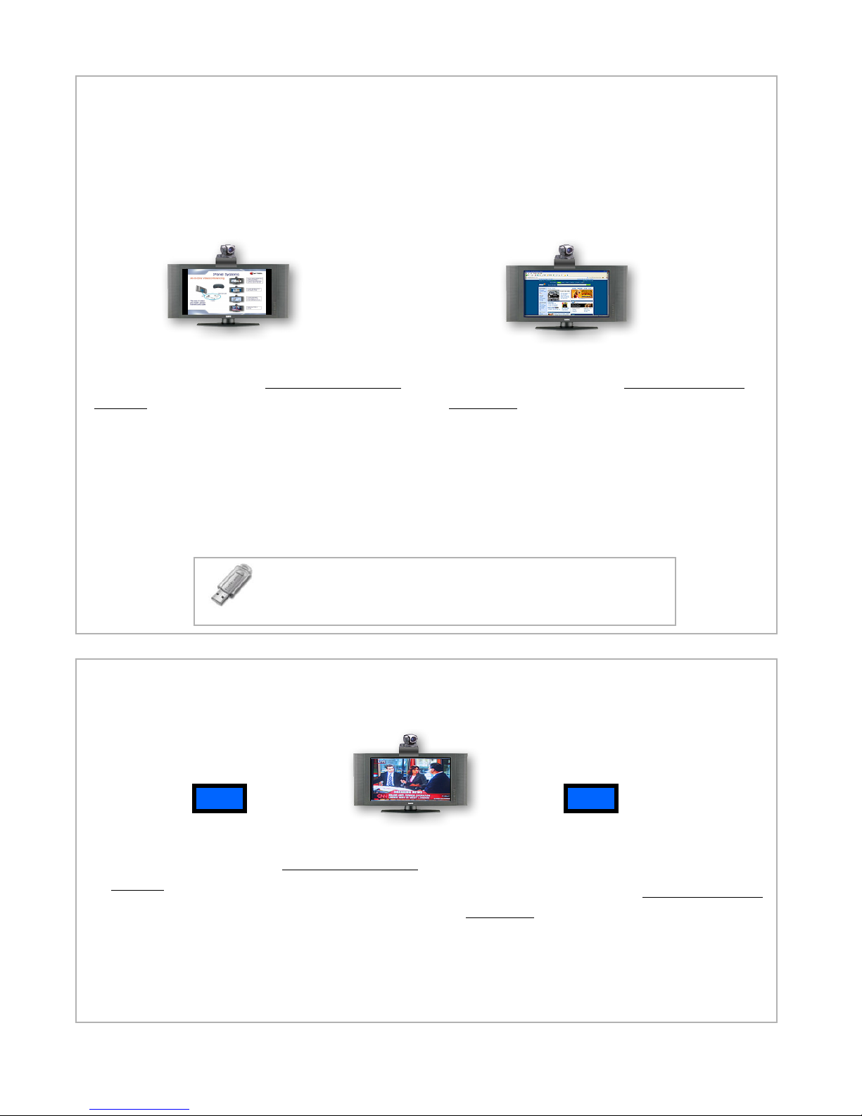
• Verify network connectivity by selecting Internet Explorer on the
IPanel and connecting to a public web site (it is the same process as
any other computer).
• Note: there are 2 Ethernet adapters on the back of the IPanel. You
can use either one, but if you are setting up a static IP address on your
IPanel make sure you setup the same network properties for the same
port you plug your cable into. (Facing the back of the iPanel adapter 1
is on the left ("Local Area Connection") and adapter 2 ("Local Area
Connection 2") is on the right. It's perfectly ok to set-up both adapters
with the same information.
)
A
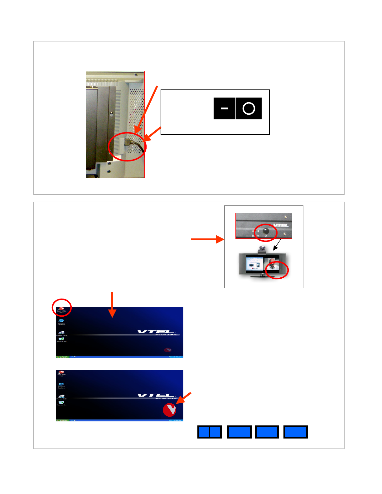
By default, your IPanel is setup to use automatic IP detection (DHCP)
on both of its Ethernet ports. If your internal network is configured to
use DHCP (which is the most common case) then simply plug in a
network cable into either port on the IPanel.
B
C
6. IPanel Network Setup for Public Internet
7. Manual control of panel display mode
If you don’t see the normal Windows XP screens during start up of the IPanel system, it is
usually because the flat panel is not in “DVI” mode (this is the computer display mode). The
Panel remembers the last mode it was displaying just before shutdown. It will be in that mode
during the subsequent startup. For example, if you were watching TV and then turned the system
off, it will restart in TV mode. You will need to go to the manual control buttons on the lower right
of the panel (on front or under the edge). Select the button labeled “input”. Press this button
slowly until you see “DVI” appear on the panel. You will cycle through seven inputs (DVI,
Cable Channel, AV1, AV2, Component 1, Component 2, and RGB).
However, if you power up and power down via the computer display mode you won’t have to
manually change the panel display mode.

7. IR
receiver
2. Video
dongle
XX
1. DVI
6. S-Video
2601/3201/4201 Series: Attaching VTEL Backpack (PC) to LCD Flat Panel
Mechanical Assembly
A. Mount the camera to the LCD monitor using the camera mounting bracket.
B. Place the camera umbilical cable (cables 3,4,5) behind the PC mounting
bracket and mount the PC assembly to the LCD monitor using four screws
Cable Assembly
1) Attach DVI cable and securely screw it in
2) Attach Video dongle
3) Attach both ends of the camera power cable (part of umbilical)
4) Attach VISCA cable to port labeled VISCA IN (camera) and other
end into upper most COM port (COM 2) (part of umbilical)
5) Attach S-Video cable to camera port and the other end into connector
on video dongle (cable 2) with arrow pointing towards PC
6) Attach one end of this cable to connector on video dongle (pointing
away from PC) and other end to the right-most S-Video receptacle
on the LCD panel
7) Attach the IR receiver to the PS/2 ports on PC.
Be sure to match the keyboard symbol with the
purple/keyboard jack and the mouse symbol
with the green/mouse jack on the PC.
5. Camera
S-Video
3. Camera
power
4. Camera
VISCA

11. Audio
10. Audio
9b. LCD
Control
13. Microphone 14. Cable TV
17. VGA to external projector
15. IP/LAN network
16. Power
adapter
Attaching VTEL Backpack to LCD Flat Panel
Cable Assembly Continued
9a) Attaching Gender Changer (GC) to 9-pin male connector on LCD panel. First, remove nuts
(if present) from GC. Second, attach GC to panel and tighten nuts . Note: it’s a tight fit.
You may need to loosen the panel connector’s hold-down nuts to lower them in order
to thread with GC’s screw. When you tighten GC’s screws it will also tighten the panel
connector’s hold-down nuts.
9b) Screw in each end of the LCD panel control cable. Be sure to use the lower COM port (COM 1)
on the PC
10) Plug one end of this audio cable into the Y-splitter. Match the red and white jacks
to their left-most audio receptacles on LCD
11) Plug one end of this audio cable into the into the Y-splitter. Match the red and white jacks
to their right-most audio receptacles on LCD
12) Plug the Y-splitter into the green mic jack on the PC.
13) Plug in microphone into pink jack on the PC
14) If available, plug in your coaxial cable TV feed for TV viewing
15) Attach your RJ-45 IP/LAN network cable to either port on PC
16) Attach the power cable here and plug the AC side into a surge protector
17) If available, attach an external VGA display/projector to the PC.
9a Gender
Changer
12. Y-Splitter
This manual suits for next models
4
Table of contents
Other VTEL Conference System manuals