SOFTLINK NB-SI2 User manual


Contents
1 Introduction 1
1.1 NB-IoT mobile data services ......................................... 1
1.2 Module usage ................................................. 1
1.3 Hardware features and power supplying .................................. 2
2 Technical parameters overview 3
3 Configuration of the NB-SI2 module 4
3.1 Setting of NB-SI2 module parameters by configuration cable ....................... 5
3.1.1 List of NB-SI2 module configuration parameters and commands ................ 5
3.1.2 ”System commands” group for control of module basic functions ................ 7
3.1.3 ”Configuration” group of commands for writing of configuration ................ 8
3.1.4 ”System commands” group for general diagnostics ........................ 9
3.1.5 ”Inputs” group parameters ..................................... 9
3.1.6 Description and setting of ”Leak” alarm function ......................... 11
3.1.7 Description and setting of ”Burst” alarm function ........................ 12
3.1.8 Setting of sensor inputs ....................................... 13
3.1.9 Description and setting of ”Tariff switching” function ...................... 14
3.1.10 Commands for message content setting ............................... 15
3.1.11 Commands for setting of message broadcasting system ...................... 17
3.1.12 Displaying of other operational entries in the list of parameters ................. 20
3.2 Setting of parameters by using of optical converter ............................ 21
3.3 Remote setting of module parameters through the NB IoT back channel ................ 26
3.3.1 Overview of module configuration parameters ........................... 27
3.4 The NB-SI2 module data messages ..................................... 28
3.4.1 Structure and types of data messages ............................... 28
3.4.2 Description of INFO message .................................... 29
3.4.3 Description of TRAP message .................................... 30
3.4.4 Encryption of messages ....................................... 31
4 Operational conditions 33
4.1 General Operation Risks ........................................... 33
4.1.1 Risk of mechanical and/or electric damage ............................. 33
4.1.2 Risk of premature battery discharge ................................ 33
4.1.3 Risk of damage by excessive humidity ............................... 33
4.2 The condition of modules on delivery .................................... 34
4.3 Modules storage ............................................... 34
4.4 Safety precautions .............................................. 34
4.5 Environmental protection and recycling .................................. 34
4.6 NB-SI2 module installation ......................................... 34
4.7 Module and meter replacement ....................................... 36
4.8 Module dismantling ............................................. 37
4.9 Functional check of the module ....................................... 37
4.10 Operation of the NB-SI2 module ...................................... 38
4.11 Using of NB-SI2 module for remote monitoring of sensors ........................ 38
5 Troubleshooting 39
5.1 Possible causes of module failures ...................................... 39
5.1.1 Power supplying failures ....................................... 39
5.1.2 System failures ............................................ 40
5.1.3 Transmitter and receiver failures .................................. 40
5.1.4 Failures of communication with meters ............................... 40
5.2 Troubleshooting procedure .......................................... 41
6 Additional information 42
NB-SI2 i

List of Tables
1 Overview of NB-SI2 module technical parameters ............................. 3
2 Overview of NB-SI2 module configuration parameters .......................... 27
List of Figures
1 View of the NB-SI2 module ......................................... 2
2”Leak” alarm function principle ....................................... 11
3”Burst” alarm function principle ...................................... 12
4 Conversion table between ”LIMIT” value and corresponding minute flow ................ 13
5”Tariff switching” function principle .................................... 15
6 Table for selection of message content (”mask”) .............................. 16
7 NB-SI2 module configuration table ..................................... 22
8 Basic forms of NB-SI2 module in ”SOFTLINK Configurator” application ............... 24
9 Input/output setting form and NB-IoT network configuration form ................... 25
10 Forms for setting of typical water supplying functions .......................... 25
11 Preview of ”NEP coding table” for coding of variables in WACO system ................ 28
12 Set of NB-SI2 module components with stick antenna .......................... 35
13 Detail of NB-SI2 module PCB ........................................ 35
14 Types of sensor outputs convenient for NB-SI2 module .......................... 38
15 Principle of ”electronic seal” sensor ..................................... 39
16 Using of position sensor for door monitoring ............................... 39
NB-SI2 ii

1 Introduction
This document describes features, parameters and setting possibilities of the NB-SI2 module, which is used for
reading of either consumption meters with pulse output (water meters, electrometers, gas-meters. . . ), or two-state
sensors (e.g. door contacts, flood detectors, fire detectors, electronic seals...etc.) and for radio-transmission of the
data from connected meters/sensors to the superior remote reading system via data services of NB-IoT operator.
1.1 NB-IoT mobile data services
Mobile data services NB-IoT are global data services provided by some operators of GSM services. The
services are focused on the communication with a huge quantity of devices, that transfer only an extremely limited
volume of data. Networks with such purpose and features are commonly labeled as ”Internet of Things”, or by its
acronym ”IoT”. NB-IoT (”Narrow Band Internet of Things”) is an open standard developed by 3GPP organization
(3rd Generation Partnership Project) which is concerned with standardization in the GSM network development.
NB-IoT is a cellular technology based on the LTE, that was developed specially for wireless communication with
terminals of IoT category, that produces only limited volume of data, but they are miniature, inexpensive, with
a very low energy consumption and they are commonly installed in the places with high demands on the signal
coverage. Typical example of such device is a reading module of the water/gas/electro-meter installed in the
basement without electricity, that should be able to run reliably many years on the internal battery even in weak
signal conditions, where other services fail.
NB-IoT technology maximally utilizes technological infrastructure of LTE data services in licensed radio band.
Combination of narrow frequency band and the most advanced modulation techniques enable increasing of receiver
sensibility to the -135 dBm level, so that an existing infrastructure of mobile operator provides global coverage
with high signal penetration even in build-up urban areas. Thus, the service is available in the places, where IoT
category devices are typically installed - in shafts, distribution boards and cellars.
Terminal devices are identified in the network by standard SIM of GSM operator. Global system of SIM evidence and
single communication standard enable providing of international services (roaming). Bi-directional communication
is carried by standard Internet protocol with UDP transport layer. Messages are transferred from the GSM operator
network to the IoT-terminal operator through the designated data gateway (Access Point - AP) either to public
Internet, or to operator’s private IP network (i.e. same way as any similar mobile data services). Addressing and
routing details depend on the network configuration and policy of particular GSM operator. Typical example of
addressing and routing is a solution, when the GSM network automatically assigns private IP addresses to IoT
terminals, IP-packets with messages are routed through the private IP network to a single Access Point, where
they are re-addressed and resend through a single pre-arranged public IP-address to the public Internet. The IoT
terminal assigns packets by target server public IP-address, that is preset in its configuration. Target system can
identify original source of the message by using of device unique identifier (IMEI), which is a requisite part of the
message content.
1.2 Module usage
The NB-SI2 module can be used either for remote reading of one or two consumption meters with pulse output, or
for monitoring of up to two two-state sensors. It is possible to combine both type of usage.
When using for remote reading of consumption meters (water meters, gas meters, electro-meters...), up to
two meters with standard pulse (”SI”) output can be connected to the module. The meters can be of different
kind, with different quantities and units and with different conversion rates. The module continuously registers
incoming pulses (generated by meters) into its internal counters, with using of preconfigured multipliers/divisors
converts current status of each counter into the required output value and broadcasts info-messages with current
statuses of connected meters in form of radio-messages of NB-IoT service provided by GSM operator (hereinafter
”INFO-message”).
When using for remote monitoring of sensor statuses (door contacts, flood detectors, fire detectors, electronic
seals..), up to two two-state sensors with ”off/on” (”0/1”) outputs can be connected to the module. The sensors
can be of different kind, with different type of output and different logic of signaling. The module continuously
monitors status of each sensor and in case of change sends immediately alarm message (message of ”TRAP” type
) to the superior system. The module stores status of the input into internal counter and transmits information
about the current status of connected sensors in regular INFO-messages.
Content of INFO-messages is configurable, it could contain current statuses of connected meters/sensors, current
statuses of embedded temperature/humidity sensors, as well as previously measured ”historical” readings stored in
NB-SI2 1

the module memory. One message can contain up to 24 historical readings. Each message always carries identi-
fication and operational data of the module (processor temperature, battery voltage, signal strength information).
These messages are handed over to the application server with using of NB-IoT service of GSM provider. The data
are transferred in form of standard IP/UDP packets, that are routed to the server of remote reading application
operator through the designated Access Point of GSM provider. Application server receives the messages and
performs their decoding, storing and further processing.
The NB-SI2 module supports bi-directional communication and it is able to receive through the network
messages of ”SET” type, generated by remote computer. These messages can be used for setting of module
parameters from the remote server.
1.3 Hardware features and power supplying
The module is enclosed in humidity-proof plastic casing with IP65 degree of protection and can be used in interiors
as well as in exteriors. The casing is designed for mounting on the wall or other construction element (beam,
pipe...). Module can be treated with an additional sealing by high-adhesion silicon filling, that can ensure proof
against inundation by water (IP68 grade). If this treatment is required from the manufacturer, it must be ordered
separately.
The module is power supplied by internal battery with up to 10 years lifetime for frequency of 2 - 4 broadcastings per
day (1 message can contain up to 24 readings). Battery lifetime can be negatively influenced by shorter broadcasting
period, or by storing and operation in sites with the temperatures exceeding the recommended range.
The module is equipped with a SIM-holder for ”Micro-SIM” (3FF) format of SIM-card (15 x 12 x 0,76 mm).
SIM-holder is placed inside the module on the PCB.
The module can be controlled and configured either by configuration cable, or wirelessly - by infra-red remote
control with using of optical converter. The module can be configured also remotely, with using of back channel of
bi-directional communication.
External appearance of the NB-SI2 module is shown in the figure 1. Position of infrared sensor for wireless con-
figuration is marked by green arrow. Newer module modifications are equipped with the special circular aperture
(”peephole”) for magnetic fixing of the optical converter.
Figure 1: View of the NB-SI2 module
NB-SI2 2

2 Technical parameters overview
Overview of NB-SI2 module technical parameters is shown in the Table1below.
Table 1: Overview of NB-SI2 module technical parameters
RF subsystem parameters
Frequency band 800 MHz (RX/TX) 791-821 / 832-862 MHz
Frequency band 850 MHz (RX/TX) 869-894 / 824-849 MHz
Frequency band 900 MHz (RX/TX) 925-960 / 880-915 MHz
Modulation GMSK, 8PSK (adaptive)
Bandwidth 180 KHz
Transmitting power 200 mW
Receiver sensitivity 135 dBm
Communication protocol NB IoT (bi-directional)
Transmission speed 0,35 ÷240 Kbps (adaptive)
Antenna connector SMA female
Antenna characteristic impedance 50 Ω
Configuration interface RS232
Transmission speed 9600 Baud
Operation mode asynchronous
Transmission parameters 8 data bits, 1 stop bit, none parity
Signal level TTL/CMOS
Optical configuration interface
Transmission speed 115 200 Baud
Optical band 870 nm
Optical interface specification IrPHY 1.4 standard
Pulse/sensor inputs
Resistance of released contact more than 10 MΩ
Resistance of short-circuited contact less than 10 kΩ
Maximum input voltage 0,25 V
Maximum frequency of input pulses 300 Hz
Minimum pulse length 20 ms
Power supplying
Lithium battery voltage 3,6 V
Lithium battery capacity 13 Ah
Weight and dimensions
Length 145 mm
Width 45 mm
Height 100 mm
Weight cca 300 g
SIM-card format (15x12x0,76)mm) ”Micro-SIM”
Storage and installation conditions
Installation environment (by ˇ
CSN 33 2000-3) normal AA6, AB4, A4
Operation temperature range (-20 ÷40) ◦C
Storage temperature range (0 ÷40) ◦C
Relative humidity * 95 % (w/o condensation)
Degree of protection * IP65 or IP68
* modules treated by additional silicon filling are waterproof with IP68 degree of protection.
NB-SI2 3

3 Configuration of the NB-SI2 module
Configuration parameters of the NB-SI2 module can be displayed and changed from the common computer (PC)
by one of these methods:
- with using of ”USB-CMOS” converter and configuration cable connected to the module;
- wirelessly, with using of ”USB-IRDA” or ”BT-IRDA” converter;
-remotely, by using of bi-directional communication system.
Technique of interconnection of the module with configuration computer and general rules of configuration are
described in detail in the chapter 2 of ”Configuration of wacoSystem product family devices”, that can be
downloaded from the producer website:
www.wacosystem.com/support/
www.softlink.cz/en/documents/
The description and meaning of all configuration parameters that can be checked and changed by cable can be
found in the section 3.1 ”Setting of NB-SI2 parameters via configuration cable”.
Description of interconnection of the converter with PC (”USB-IRDA”) or smartphone (”BT-IRDA”) and gen-
eral rules of configuration with using of optical converters are described in the chapter 3 of above mentioned
manual ”Configuration of wacoSystem product family devices”. The description and meaning of the parameters
that can be changed by optical converter can be found in the section 3.2 ”Setting of parameters by using of optical
”IRDA” converter”.
Principles and short description of communication through the NB-IoT back channel can be found in para-
graph i 3.3 ”Remote setting of module parameters through the NB IoT back channel”.
NB-SI2 4

3.1 Setting of NB-SI2 module parameters by configuration cable
In following part of the document there is a description of these parameters of the NB-SI2 module, that can be
displayed and examined from PC connected to the module by configuration cable. Some of the parameters can be
changed by configuration commands entered ”from the console”.
3.1.1 List of NB-SI2 module configuration parameters and commands
List of all configuration parameters of the module can be displayed by entering of ”show” command and pressing
of ”ENTER” key. The following list of parameters will display in the terminal window:
mon#show
----- Configuration -----
Timezone : 1
Server IP : ’92.89.162.105’
Server port : 2000
Reply to server : no
My src port : 2000
APN : ’’ "
Max session time 172800 sec - 2d, 0:00:00
Input[0] ,multiplier 1,divider 1,mode falling, quick, alr:none, alarm code OK 8, Error 9
Leak detection periode 12 hour(s), zero periode 30 minutes
Input[1] ,multiplier 1,divider 1,mode falling, quick, alr:none, alarm code OK 8, Error 9
Send periode : 120 min.
Hist. periode : 15 min.
in message 8 records, max. is 24 recs
Send mask is 3 : I1, I2
Data will be unencrypted
Next send : 88 min.
No. sent : 11 msg(s)
No. recv : 0 msg(s)
-- Modem status --
Modem state : 0
Session count : 1
Session timeout : 172796 sec - 1d, 23:59:56
Modem IMEI : 863703038894247
SIM CCID : 89882390000037252304
SIM IMSI : 901288001028645
Last RSSI : -61 dBm
Conf. version : 12
SW version 1.07, date Mar 2 2020
mon#
List of all configuration commands (”HELP”) can be displayed by entering of ”?” command into the command
line and pressing of ”ENTER” key. The following list of commands will display in the terminal window:
NB-SI2 5

mon#?
Help :
--- System commands ---
deb : Show or set debug level
ta : Show tasks
mb : Show mail boxes
du addr : Dump memory
rb addr : Read byte from addr
rw addr : Read word from addr
rd addr : Read dword from addr
sb addr val : Set byte on addr
sw addr val : Set word on addr
sd addr val : Set dword on addr
port : Show port [a,b,..]
show : Show info
write : Write configuration to flash
cread : Read configuration from flash
clear : Clear configation and load defaults
--- Inputs ---
val : Show or set counters values[0-1]
mul : Set multiplier of value[0-1]
div : Set divider of value[0-1]
det : Detection 0 - falling, 1 - rising
dmode : 0 - quick, 1 - slow
alr : Send alarm : 0 - none, 1 - falling, 2 - rising, 3 - both
alcok : alarm code OK
alcerr : alarm code Error
leakp : Leak detection periode in hours - 0 disabled
leakz : Leak zero periode in minutes (rounded up to ten minutes)
burstp : Burst min puls in 10 minutes
burstt : Burst check time in minutes (rounded up to ten minutes)
trf : Set tarrif 0 - off, 1 - t1 high, 2 - t1 low
--- Utils ---
ekey : Set encrypt key, point ’.’ no encrypt
periode : Send periode 0 - disable, >0 periode in minutes
sendp : Send x NB messages
send : Send data
smask : Send mask bits, 0 - I1, 1 - I2, 2 - temp. 3 - hum. ,default 3 - I1 and I2
hist : History periode 0 - disable, >0 periode in minutes
hdata : Show history data
fdata : Fill n history data
server : Server IP address
sport : Server UDP port
sreply : Send reply to server
apn : Access Point Name
sess : Set max session time in minutes
tshort : Set modem short timeout
tlong : Set modem long timeout
tconn : Set modem connection timeout
info : Show or set manuf. info string (0-30 chars)
tz : Time offset in hours
ppm : Set RTC ppm
time : Show or set rtc time, set as BCD : 0x102033 is 10:20:33
date : Show or set rtc date, set as BCD : 0x171231 is 2017-12-31
uptime : Show uptime
sens : Show sensors
reset : Reset device
at : Test modem
? : Show this help
mon#
NB-SI2 6

Overview of configuration parameters with short description of their meaning can be also found in table 2on the
page 27. The meaning of individual parameters and detailed description of their usage can be found in the following
part of chapter 3.1.
3.1.2 ”System commands” group for control of module basic functions
This group of commands enables control of basic functions of the module. There are following commands:
reset command for module reset
send immediate sending of radio message
sendp immediate sending of series of messages
sens show current values of internal sensors (temperature, voltage..)
uptime show system uptime from last reset
info setting of individual module description
The command ”reset” performs the module reset. After each reset the system starts with the parameters that are
stored in FLASH memory. If the current configuration should be used after reset, it is necessary to store it into the
FLASH before reset (see paragraph 3.1.3). Example of using of ”reset” command:
cfg#reset
-- Reset code 0x14050302 --
PIN Reset
SFT Reset
SW version 0.01, date Jan 18 2019
Monitor started ..
mon#
The command ”send” can be used for immediate (”out of turn”) transmitting of the standard information message
with measured values. This command can be used for checking of radio signal availability during the system
installation, or for any adjustments and testing of the module. The command makes possible to send the information
message anytime without necessity to change the transmission period or without waiting until the message will be
sent spontaneously within the pre-set period. Example:
cfg#send
Sending ...
send [1] msg 255
mon#
The command ”sendp” can be used for immediate transmitting of series of standard messages with 1-minute
interval. This command can be used for checking of radio signal availability during the system installation. It could
enable checking of connection also after closing of mounting rack, or after leaving of watemeter shaft. Number of
transmitted messages is set by parameter (number) after command, the first message is transmitted immediately
after command. Example of sending of series of 5 messages:
cfg#sendp 5
sending 5 msgs
mon#
The ”sens” command can be used for displaying of current values of A/D converters measuring physical quantities
(battery voltage, temperature...). This command is intended only for module checking and diagnostics.
cfg#sens
-- Sensors --
CPU : 25.8 ◦C
VDA : 3.003 V
VBAT : 3.561 V
Sensor type 0
mon#
The ”uptime” parameter value shows the time interval passed from the last device reset in seconds so that the
exact moment of the last module reset can be recognized by this parameter. The parameter is of ”read only” type.
Example:
NB-SI2 7

cfg#uptime
Uptime 0d, 0:13:26
mon#
The ”info” command can be used for setting of individual description/label of the module. Up to 30 alphanumeric
characters can be entered. The label will be displayed in the ”Info text” field of the optical configuration form. The
label can contain any identification data (installation site code, customer code, meter serial number. Example of
module individual text setting:
cfg#info NB-X 123456
Change manuf info from : ’’ to : ’NB-X 123456’
mon#
3.1.3 ”Configuration” group of commands for writing of configuration
The module contains two sets of configuration: operating configuration and saved configuration. At the start of the
system the module copies saved configuration to operating configuration, with which continues to work. If the user
changes configuration parameters, it does so only in operating configuration.
If the current operating configuration was not stored to FLASH memory, the module returns to the saved config-
uration after reset. If the parameter should be changed only temporarily (for example shorten of the broadcasting
period during installation), it is not necessary to save operating configuration into FLASH memory (after finishing
a work the module can be returned to normal configuration by its reset). If the parameter should be changed
permanently, there is necessary to save configuration to FLASH memory.
If operating configuration corresponds to the saved set (ie. there are no differences between commands in FLASH
and in the operating set), the module will ”report“ prompt in the format ”mon#”. If operating configuration was
changed so that it no longer matches to the saved set, the module will report prompt in the format ”cfg#”.
Every time the current configuration is saved into FLASH memory the value of the ”Configuration version” param-
eter increases by one and the prompt changes to ”mon#”. The parameter resets to zero by erasing of FLASH.
Current operating configuration can be displayed by using of ”show” command (see paragraph 3.1.1):
cfg#show
Current operating configuration can be rewrite the to FLASH memory by using of ”write” command:
cfg#write
Writing config ... OK, version 13
mon#
Reading of the configuration from FLASH memory can be done by using of ”cread” command:
cfg#cread
Reading config ... OK, version 13
mon#
The configuration can be erased in Flash memory by using of ”clear” command:
cfg#clear
Clearing config ... OK, version 13
mon#
This command deletes all configuration parameters from the FLASH memory, so it is necessary to set them again.
If after erasing all parameters in FLASH memory the module goes to reset, default set of parameters (configured
in the program of the device) is duplicated to FLASH memory. There is only one exception - frequency constant
keeps the actual value also after cleaning of FLASH memory by ”clean” command.
This command is recommended to use only by users with good knowledge of the system or after
consultation with the manufacturer.
NB-SI2 8

3.1.4 ”System commands” group for general diagnostics
Commands ””deb”, ”ta”, ”mb”, ”du addr”, ”rw addr”, ”rb addr”, ”rd addr”, ”sw addr val”, ”sb addr
val”, ”tshort”, ”tlong”, ”port”, ”ppm” and ”at” are used for troubleshooting and repair of the device in a
factory. Manufacturer strongly recommends not to use these commands during common operation.
3.1.5 ”Inputs” group parameters
This group of parameters and commands enables setting of internal pulse registers (counters) and setting of output
values of the module.
The NB-SI2 module is equipped with two inputs (port 1 and 2), that are connected to the corresponding pulse
counters (index 0 and 1). Each counter increases its value up one unit each time it receives pulse from a consumption
meter connected to its port. Below listed commands are used for settings of the initial counter values and constants
(multipliers, divisors) that can be used for adjusting of the output statuses to required values, and for setting of
special function ”leak” and ”burst” for detecting of anomalies in the course of consumption (see detailed description
in the paragraph 3.1.6 and 3.1.7).
Each input can be switched to so called ”alarm mode”, in which after each change of input value the counter
only changes its status (goes from ”0” to ”1” or vice versa) and the module transmits the message immediately
with the change of status. Thus the module can read and transfer status information from binary sensors (e.g.
door contacts, flood detectors..). Detailed description of setting of inputs in alarm mode can be found in the
paragraph 3.1.8 ”Settings of sensor inputs”.
Setting of pulse inputs can be performed with using of following commands:
val[index] initial counter value setting
mul[index] setting of multiplier (output value = status * multiplier)
div[index] setting of divisor (output value = status / divisor)
det[index] setting of trigger edge (0 - falling edge, 1 - rising edge)
dmode[index] setting of pulse input mode (0 - quick pulses, 1 - slow pulses)
alr[index] setting of alarm mode (sensor input setting)
alcok[index] specification of alarm mode for ”OK” status (sensor input setting)
alcerr[index] specification of alarm mode for ”Error” status (sensor input setting)
leakp[index] period of leak detection setting (see ”leak” function)
leakz[index] zero interval of leak detection setting (see ”leak” function)
burstp[index] burst alarm limit setting (see ”burst” function)
burstt[index] burst measuring interval setting (see ”burst” function)
trf[index] setting of second input into the tariff switching mode (see ”tariff” function)
By using of ”val[index]” command an initial (or actual) value of the counter can be set. After the value is
setup, it increases from this value with each new-coming pulse. Actual counter value can be displayed by using of
”val[index]” command (without parameter). Counter status can be set to required value by using of ”val[index]”
command followed by required whole number (integer).
Example of setting port No 1 (index=0) counter to ”1892” value and follow-up checking of correctness of the
configuration:
cfg#val0 1892
Value[0] changed from 1565252980 to 1892
cfg#val0
Value[0] : 1892 * 1 / 1 -> 1892
cfg#
It is evident from the example, that when checking of current status by ”val[index]” command, the system displays
not only current status value, but also current settings of multiplier and divisor and output value after multiply-
ing/dividing.
By using of ”mul[index]” and ”div[index]” commands a value of multiplier and divisor can be set to the counter.
Default setting of both values is ”1”. If it is necessary to adjust the counter value by some coefficient, enter
convenient combination of multiplier and divisor as shown in example below.
Actual value of multiplier and divisor can be displayed by using of ”val[index]”, ”mul[index]” or ”div[index]” com-
mands (without parameter) as shown in the example:
NB-SI2 9

cfg#mul0
Multiplier[0] = 1
cfg#div0
Divider[0] = 1
cfg#
Multiplier and divisor setting example:
Watermeter generates measuring pulses after each 50 litres of consumed water. So as to indicate water consumption
in m3, it is necessary to adjust the original counter value by using of multiplier and divisor as shown in the example:
50 litres = 0.05 m3, so to convert the value to m3, it must be multiplied by 5/100.
It could be done by setting of multiplier to ”5” and divisor to ”100” - see example:
cfg#mul0 5
Value[0] changed from 1 to 5
cfg#div0 100
Value[0] changed from 1 to 100
cfg#val0
Value[0] : 2000 * 5 / 100 -> 100
cfg#
From the display of summary shown in the last sequence of commands it is evident that current status value (2000)
will be interpreted as output value 100 (m3). As one unit of the counter represents 50 litres, output value of the
counter is: 2000*50 = 100 000 litres = 100 m3.
By using of ”det[index]” command a trigger edge of the counter could be chosen. If it is preset to ”0” op-
tion (default setting) the value of counter will increase with falling edge of incoming pulse (i.e. when the mechanical
contact is short-circuited, or when an electronic pulse generator goes from ”1” to ”0”). If it is preset to ”1” option,
the value of counter will increase with rising edge of incoming pulse (i.e. when the mechanical contact is released,
or when an electronic pulse generator goes from ”0” to ”1”). Actual value of trigger edge setting can be displayed
by using of ”det[index]” command (without parameter).
Example of setting of trigger edge for port No 1 (index=0) to ”1” option (rising edge) and follow-up checking of
trigger edge setting of all ports:
mon#det0 1
Det[0] = 1 - rising
cfg#det
Det[0] = 1 - rising
Det[1] = 0 - falling
cfg#
By using of ”dmode[index]” command a smoothening (equalizing) filter of pulse input could be involved or
disconnected. If it is preset to ”0” option (default setting) the equalizing filter is switched off and the input is preset
for detecting of high frequency (quick) pulses. If it is preset to ”1” option, the equalizing filter that can suppress
disturbing pulses on the input is switched on. This setting could be used if there are some parasitic pulses on the
pulse input (e.g. if the input wire is too long), but using of this filter is restricted only for sensor input, or for
detecting of slow pulses with maximum frequency of 2 Hz (minimum length of pulse is 250 ms).
Example of setting of port No 1 (index=0) mode to ”1” option with involved equalizing filter (slow pulses):
cfg#dmode1 1
Mode[1] = 1 - slow
cfg#
Detailed description of ”Leak” alarm function can be found in the paragraph 3.1.6 below. Detailed description of
”Burst” alarm function can be found in the paragraph 3.1.7 below. Detailed description of sensor input settings can
be found in the paragraph 3.1.8 ”Setting of sensor inputs” below. Detailed description of ”tariff switching” function
can be found in the paragraph 3.1.9 below.
NB-SI2 10

3.1.6 Description and setting of ”Leak” alarm function
”Leak” function is used for detection of such situations in the consumption of gas, water or other liquids, when
there are permanent low-quantity losses caused by minor leaks in the distribution system. In view of the fact that
remote reading systems don’t record consumption continuously but in some steps (usually given by full turn of its
measuring disk), it could take quite long time until the trouble is discovered.
”Leak” function is based on the common pattern that during the normal long-term (e.g. day, week) operation there
are usually some regular time intervals, when the consumption is in its ”idle” status, because the gas/liquid is not
consumed from natural reasons (e.g. during the night, or out of working hours). In these idle time intervals the
consumption should be zero volume. If there are any leaks, time intervals with zero consumption practically either
do not occur, or there are only short intervals caused by discontinuity of measuring system (e.g. if one metering
pulse represents 100 litres, minor leak could become evident even after several hours, when such quantity will leak).
”Leak” function principle is shown in the figure 2. When setting of ”Leak” alarm function the length of detection
period must be entered by setting of ”Leak Detection Period” parameter. After expiration of this period the
system evaluates whether during this period at least one time occurred the situation, when the consumption was
in zero level during preset time interval (entered by ”Zero Period” parameter). If there is no leakage, it is highly
probable that zero consumption period occur at least once during the period and system evaluates the period as
”no alarm” status (see upper part of the figure 2). But if there is no one interval with zero consumption registered
during whole detection period, module transmits to superior system ”Leak” alarm message (see lower part of the
figure 2).
Figure 2: ”Leak” alarm function principle
”Leak” function can be activated for chosen port by using of leakp[index] command that defines the length of
detection period (”Leak detection period” parameter) in hours. By using of leakz[index] command setup
concurrently for the same port the length of zero consumption interval (”Zero period” parameter) in minutes.
If one of these parameters is set to ”0” for some port, ”Leak” function is deactivated for that port.
Example of setting ”Leak detection period” parameter for port No 1 (index ”0”) to 24 hours value:
cfg#leakp 0 24
Value[0] changed from 0 to 24
cfg#
Detection period can be set in range of 1 - 1090 hours, typical setting is 24 hours (daily operational cycle), or 168
hours (weekly operational cycle). Detection period starts running from module restart, or from the moment when
the parameter is changed. Alarm message is sent at the end of detection period.
Example of setting ”Zero period” parameter for port No 1 (index ”0”) to 60 minutes value:
NB-SI2 11
cfg#leakz 0 90
Value[0] changed from 0 to 90
cfg#
Zero consumption period can be set in range of 1 - 1090 minutes with precision of ten minutes (rounded to tens of
minutes, e.g. 10, 20, 30...). If the command is entered with any other value (e.g. 36 minutes) the system will store
rounded value anyway (in this case 40 minutes). General principle is that setting of zero period parameter to longer
values means that the detection is more sensitive (it is capable to detect smaller leaks), but it is also less reliable
with higher probability to produce false alarm due to real consumption caused by random changes of operating
cycle (e.g. if somebody was held up at work few hours longer).
Setting of ”Leak” alarm function parameters appears in the List of configuration parameters (”show” command),
in the section of the particular port:
Input[0] ,multiplier 0 ,divider 1 ,mode falling, quick, alr: none
Leak detection periode 24 hour(s), zero periode 90 minutes
Structure of alarm message of ”LEAK” type is described in the paragraph ”Description of TRAP type message”.
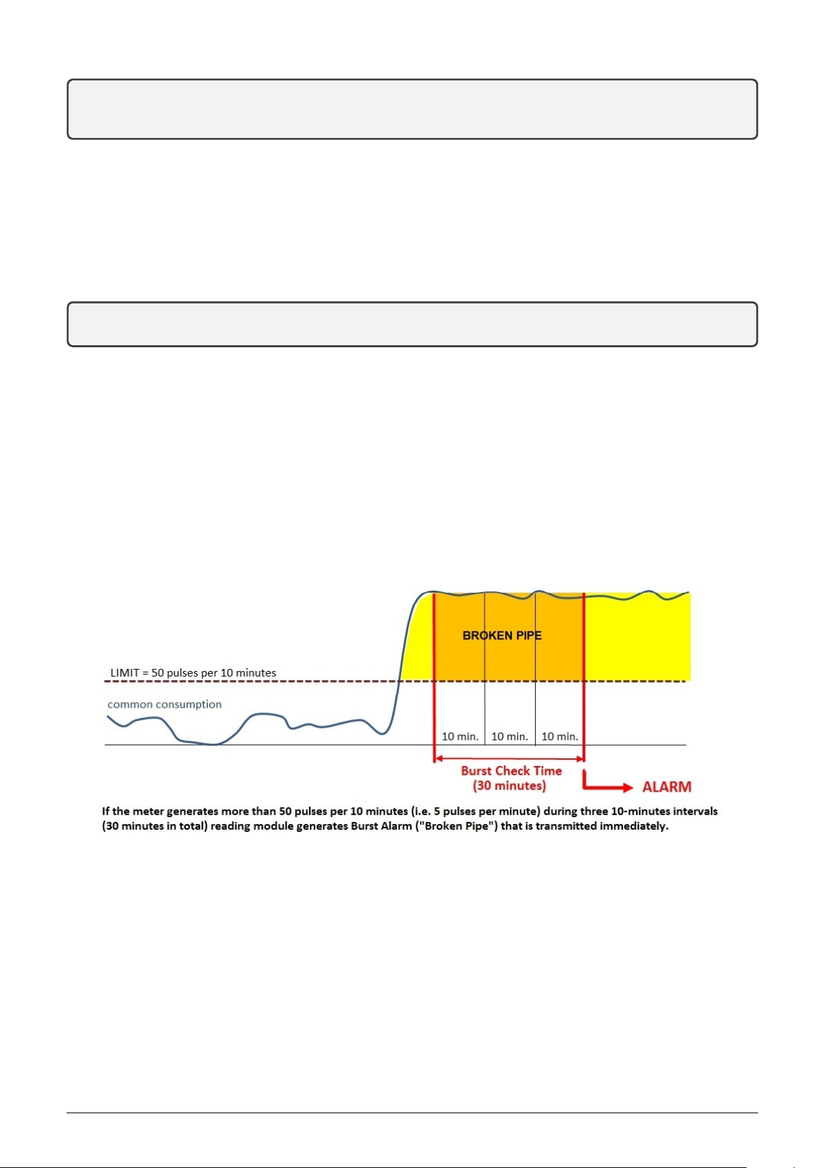
3.1.7 Description and setting of ”Burst” alarm function
”Burst” function is used for detection of such situations in the consumption of gas, water or other liquids, when the
burst consumption caused by broken pipe (or similar fatal failure of distribution system) occurs. If the consumption
of liquid/gas is abnormally huge for some period of time, the module transmits to superior system ”Broken Pipe”
alarm message.
”Burst” function principle is shown in the figure 3.. ”Burst” alarm function is set-up by entering of the burst
consumption limit (”burstp[index]” command), that means the limit over which the consumption is considered
as abnormal, and entering of ”Burst Check Time” period (”burstt[index]” command) that means the minimum
time period during which the consumption must be permanently over limit to detect the ”Broken pipe” alarm.
Figure 3: ”Burst” alarm function principle
In view of the fact that different meters connected to the module could have different conversion rate of volume per
measuring pulse, consumption limit is delimited universally as number of registered pulses per 10 minutes
time period. Conversion table between ”pulses per 10 minutes” and ”consumption per minute” for frequently
used conversion rates of watermeters is available in the figure 4.
”Burst” function can be activated for chosen port by using of burstp[index] command that defines required con-
sumption limit in number of pulses per 10 minutes period. By using of burstt[index] command setup concurrently
for the same port minimum duration of abnormal consumption (”Burst Check Time”) in minutes. If one of these
parameters is set to ”0” for some port, ”Burst” function is deactivated for that port.
Example of setting ”LIMIT” parameter for port No 1 (index ”0”) to 15 pulses per 10 minutes:
NB-SI2 12

Figure 4: Conversion table between ”LIMIT” value and corresponding minute flow
cfg#burstp 0 15
Value[0] changed from 0 to 15
cfg#
Consumption limit alarm value can be set in practically unlimited range (1 to 65535 pulses per 10 minutes).
Example of setting ”Burst Check Time” parameter for port No 1 (index ”0”) to 40 minutes value:
cfg#burstt 0 40
Value[0] changed from 0 to 40
cfg#
Minimum duration of abnormal consumption (”Burst Check Time”) can be set up in range 1 - 1090 minutes with
precision of ten minutes (rounded to tens of minutes, e.g. 10, 20, 30...). If the command is entered with any other
value (e.g. 36 minutes) the system will store rounded value anyway (in this case 40 minutes). General principle
is that setting of Burst Check Time parameter to longer values means that the detection is more reliable, with
lower probability to produce false alarm due to random changes in normal operation (e.g. during filling a tank with
water), but in the same time it will prolong the response time between the breakdown and sending of alarm.
Setting of ”Burst” alarm function parameters appears in the List of configuration parameters (”show” command),
in the section of the particular port:
Input[0] ,multiplier 0 ,divider 1 ,mode falling, quick, alr: none
Broken pipe min. 15 pulse/10 min. during 40 minutes
Structure of alarm message of ”BURST” type is described in the paragraph ”Description of TRAP type message”.
3.1.8 Setting of sensor inputs
Any two-state sensors of ”on/off” (0/1) type with contact, relay, or electronic binary output (e.g. door contacts,
flood detectors, fire detectors, electronic seals...etc.) can be connected to any of two NB-SI2 module ports. If the
port is not preset to ”alarm mode”, the module only stores number of 0/1 transitions of the sensor into the counter
and transmits the number in periodical info-messages. If, as an example, the door contact is connected to the
port, the module registers each open/close cycle and regularly broadcasts number of cycles from last reset of the
counter. If it is required to send a message immediately after each opening/closing of the door, it is necessary to
preset the port (counter) into the alarm mode. For increasing of detection reliability it is recommended to involve
equalizing filter for each sensor input as described above (see description of ”dmode” command). By involving
the filter, the detection will be more resistant to false alarms caused by any signal disturbances on the input wire.
”Alarm mode” can be activated for chosen port by using of ”alr[index]” command, followed by parameter with 0,
1, 2 or 3 value. If ”0” value is preset, alarm mode is switched off. If ”1” value is entered, the input is switched to
alarm mode and generates alarm in 1-to-0 transition (e.g. when the smoke sensor contact is switched on). If ”2”
value is entered, the input is switched to alarm mode and generates alarm in 0-to-1 transition (e.g. when the door
are opened and the door contact is switched off). If ”3” value is entered, the input is switched to alarm mode and
generates alarm in both transitions (e.g. when the door is opened as well as when it is closed) .
Example of setting port No 2 (index ”1”) to ”2” value, where the module transmits alarm when the sensor goes to
”1” status (released contact), and follow-up checking of settings of all ports:
NB-SI2 13

cfg#alr1 2
Alr[1] = 2 - rising
cfg#alr
Alr[0] = 3 - both
Alr[1] = 2 - rising
cfg#
As shown in the example, second port was switched to alarm mode with sending an alarm only in 0-to-1 transition
(released contact). From the follow-up checking of all ports status (by using of ”alr” command without index) it is
clear, that there is the alarm mode with both announced transitions on the first port.
Alarm message always contains actual status after transition (value is ”0” or ”1”) and a relevant port identifi-
cation.
If some of the inputs is preset to alarm mode, actual status of the connected sensor is regularly broadcasted also in
each info message in the same format, as used in alarm message.
On basic (factory) setting the alarm messages are universally interpreted as ”alarm on input” (OID 60 value ”9”)
and ”transition into normal status” (OID 60 value ”8”). By using of couple of ”alcok[index]” and ”alcerr[index]”
commands more accurate interpretation of the events can be preset for concrete input (e.g. ”Fire sensor ON” /
”Fire sensor OFF” couple). Actual list of alarm codes is available at the NEP Page website.
Current setting of alarm message interpretation codes can be found with using of the commands without parameter:
mon#alcok
AlamrOK[0] = 8
AlamrOK[1] = 8
cfg#alcerr
AlamrErr[0] = 9
AlamrErr[1] = 9
cfg#
Example of setting ”13” and ”14” alarm codes (door open / door close) for the first input:
mon#alcok0 14
AlamrOK[0] = 14
cfg#alcerr0 13
AlamrErr[0] = 13
cfg#
After the previous change setting of alarm interpretation is as follows:
cfg#alcok
AlamrOK[0] = 14
AlamrOK[1] = 8
cfg#alcerr
AlamrErr[0] = 13
AlamrErr[1] = 9
cfg#
This setting will be displayed in the row of relevant input of the List of configuration parameters as follows:
Input[0],multiplier 1,divider 1,mode falling, quick, alr: rising, alarm code OK 14, Error 13
It is evident from the setting, that the alarm message of ”Alarm on 0 input” type will be sent on the transition of
input into the ”1” status (interrupted contact) and will be interpreted by alarm code ”13” (OID 60, value 13 - see
paragraph 3.4.3 ”Description of TRAP type message”), meaning of which is ”alarm on the door contact”.
3.1.9 Description and setting of ”Tariff switching” function
When the ”Tariff switching” function activated, all input pulses are carried only to the first input. The second
physical input is connected to the tariff switching control voltage (see figure 5). Input pulses from the first port
NB-SI2 14

are alternatively switched to both counters in accordance with the tariff switching control voltage status, what
means that during high tariff (t1) the pulses are directed to the first counter and during low tariff (t2) they are
directed to the second counter.
Figure 5: ”Tariff switching” function principle
The function can be switched on by trf[index] command followed by parameter with 0, 1 or 2 value. Default setting
with ”0” value of the parameter means that the tariff switching function is disabled. By setting of ”1” value the
pulses are directed to the first counter (”t1”) when the tariff switching control voltage on the second port is in ”1”
status (”high”, released contact). By setting of ”2” value the pulses are directed to the ”t1” counter during ”0”
(”low”, closed contact) status of control voltage (see figure). As only the second port of the NB-SI2 module can be
used for tariff switching, the ”trf” command should be always entered with index ”1”.
Example of setting port No 2 (index ”1”) to ”1” value, when the module registers pulses to the first counter (t1)
during ”high” status of the tariff switching control voltage on the second port:
cfg#trf1 1
Change Tarrif[1] = t1 high
cfg#
Example of setting port No 2 (index ”1”) to ”2” value, when the module registers pulses to the first counter (t1)
during ”low” status of the tariff switching control voltage on the second port:
cfg#trf1 2
Change Tarrif[1] = t1 low
cfg#
3.1.10 Commands for message content setting
This group of commands serves for setting of content of NB-SI2 module information message. There are following
commands:
smask setting of content (selection of transferred information)
hist historical readings storing period
hdata displaying records in memory of historical readings
fdata inserting records into the memory of historical readings
The ”smask” command can be used for setting of information message content. Message structure is described
in ”mask” table (see figure 6), where there are different masks in different rows (one mask in one row) and all
transferred information of one particular mask are marked by ”1” in corresponding column. Binary symbols 0/1
from each four columns (Humidity, Temperature, Pulse input 1 and Pulse input 2) put together four-bit binary
number. Decimal form of this number can be used as ”smask” command parameter.
Required ”mask” of message content can be entered by entering of mask decimal number (= number in ”Mask”
column) after ”smask” command. Example:
cfg#smask 3
Send mask changed to 3 : I1, I2
mon#
As it is clear from the example, in the messages with mask number ”3” there will be transferred only values of both
counters (without temperature and humidity information).
NB-SI2 15

Figure 6: Table for selection of message content (”mask”)
As NB-IoT services are typically charged per volume of transferred data, it is important to set appropriate message
structure, that transfers only data that are really useful. If, as an example, only one sensor is connected to the
module, it is senseless to transfer status of unused counter in each message.
Due to decreasing of broadcasting frequency (saving of battery lifetime) the module enables transfer of higher
number of before read values in one message. In this case the message does not contain current values of meters,
but it contains an array of previously performed readings, that were stored in module internal memory (hereinafter
”historical readings”). Each set of historical readings is accompanied by the time of reading (”timestamp”) and
this timestamp is also transferred to the central system. Memory volume enables storing up to 24 historical
readings. Historical readings are stored into the memory with adjustable period, that should be proportionate to
broadcasting period so as the message would contain no more than 24 historical readings. Memory of historical
readings is cleared out after each message transmission
Example: If broadcasting period is set to 240 minutes (4 hours) and historical readings storing period is set to 30
minutes, there will be 240/30 = 8 readings that will be stored during whole broadcasting period. In this case the
transmitted message will contain an array of 8 historical readings.
Current setting of historical readings will display in the configuration statement as follows:
Send periode : 60 min.
Hist. periode : 10 min.
in message 6 records, max. is 24 recs
Send mask is 3 : I1, I2
It is clear from the abstract, that broadcasting period is 60 minutes, historical readings are stored every 10 minutes
and each message contains only 6 historical readings.
The historical readings storing period can be preset by using of ”hist” command followed by parameter. The
parameter is required number of minutes. Allowed values of the parameter are 10, 15, 30 and 60 minutes (if other
value entered, system will store nearest value). If the parameter is set to ”0” (default setting), no historical readings
are stored and only current values are transferred.
Example of setting of historical readings storing period to 30 minutes value:
cfg#hist 30
History changed from 0 to 30 min.
cfg#
The ”hdata” command can be used for displaying of currently stored historical readings. Example:
cfg#hdata
History data :
2018-01-04, 13:30:00+01
I1 : 1233
I2 : 127
2018-01-04, 13:40:00+01
I1 : 1249
I2 : 129
2018-01-04, 13:50:00+01
I1 : 1251
I2 : 134
cfg#
NB-SI2 16

As seen in the example, from last message transmitting there are three sets of historical readings stored in the
memory.
The ”fdata” command can be used for filling of fictive historical data into the memory. Required number of sets
should be entered after ”fdata” command. This command can be used only for module diagnostics or for testing of
decoding system. Fictive historical readings contain zero values.
Example of command for storing of 5 sets of historical readings into the module memory:
cfg#fdata 5
Fill 5 history recs
cfg#
Fictive historical readings can be checked by ”hdata” command.
3.1.11 Commands for setting of message broadcasting system
This group of commands enables setting of system for radio-broadcasting of the information messages. There are
following commands:
ekey setting of encryption key (”.” - encryption disabled)
periode setting of regular messages broadcasting period
server setting of target server IP-address
sport setting of target server port number
sreply redirection of replies to target server
apn setting of private network Access Point Name (APN)
sess maximum session time
tconn connection setup timeout
tz setting of time zone (UTC + n)
time real time (RTC) displaying/setting (hh:mm:ss)
date real time (RTC) displaying/setting (RR.MM.DD)
The command ”Encryption key” is used for setting of the encryption key for an encryption of transmitted
messages by using of AES-128 key. The encryption key of 16 bytes length is entered by using of ”ekey“ command,
followed by the string of 16 bytes that can be entered in a decimal or hexadecimal format (see examples).
An example of insertion of the encryption key in hexadecimal format:
cfg#ekey 0x1a 0x2b 0x3c 0x4d 0x5e 0x6f 0xa1 0xb2 0xc3 0xd4 0xe5 0xf6 0x77 0x88 0x99 0xaf
Setting encryption key : 1a 2b 3c 4d 5e 6f a1 b2 c3 d4 e5 f6 77 88 99 af
cfg#
An example of insertion of the encryption key in decimal format:
cfg#ekey42 53 159 188 255 138 241 202 136 21 98 147 235 15 145 136
Setting encyption key : 2a 35 9f bc ff 8a f1 ca 88 15 62 93 eb 0f 91 88
cfg#
If the encryption key is set to the module’s configuration, an information ”Data will be encrypted by AES”
displays in the list of configuration parameters (see paragraph 3.1.1)
Encryption can be switched off by setting of ”.” (dot) parameter after the ”ekey“ command:
cfg#ekey.
Encyption disabling
cfg#
In this case an information ”Data will be unencrypted” appears in the list of configuration parameters .
”Periode” command serves for setting of broadcasting period of regular info messages. The value of the param-
eter is factory preset to 60 minutes. Current value can be checked by ”periode” command (without parameter).
Broadcasting period can be changed by entering of required number of minutes (theoretically up to 65535 minutes)
after ”periode” command.
NB-SI2 17
This manual suits for next models
1
Table of contents
Other SOFTLINK Conference System manuals


