SOFTLINK WB169-SI2 User manual

Contents
1 Introduction 1
1.1 Wireless M-BUS Communication Protocol ................................ 1
1.2 Module usage ................................................. 1
1.3 External synchronization, tariff switching and alarm functions ...................... 2
1.4 Bi-directional communication mode ..................................... 2
1.5 Hardware features and power supplying .................................. 3
1.6 Variants and ordering codes ......................................... 3
2 Technical parameters overview 4
3 Configuration of the WB169-SI2 module 5
3.1 Setting of WB169-SI2 module parameters by configuration cable .................... 5
3.1.1 List of module configuration parameters .............................. 5
3.1.2 Displaying the List of configuration commands (”HELP”) .................... 6
3.1.3 ”System commands” group for general diagnostics ........................ 7
3.1.4 Commands for writing of configuration and reset ......................... 7
3.1.5 ”WMBUS” group commands for setting of messages ....................... 8
3.1.6 ”Inputs” group parameters ..................................... 11
3.1.7 Description and setting of ”Leak” alarm function ......................... 15
3.1.8 Description and setting of ”Burst” alarm function ........................ 16
3.1.9 Setting of sensor inputs ....................................... 17
3.1.10 Description and setting of ”Tariff switching” function ...................... 19
3.1.11 ”Modem commands” group for RF-subsystem diagnostics .................... 20
3.1.12 Commands of ”Utils” group for setting of module common functions .............. 20
3.1.13 Overview of module configuration parameters ........................... 22
3.2 Setting of parameters by using of optical ”USB-IRDA” converter .................... 24
3.3 Structure of module data messages ..................................... 28
3.3.1 Iinformation message ......................................... 28
3.3.2 Alarm message ............................................ 30
4 Operational conditions 32
4.0.1 Risk of mechanical and/or electric damage ............................. 32
4.0.2 Risk of premature battery discharge ................................ 32
4.0.3 Risk of damage by excessive humidity ............................... 32
4.1 The condition of modules on delivery .................................... 33
4.2 Modules storage ............................................... 33
4.3 Safety precautions .............................................. 33
4.4 Environmental protection and recycling .................................. 33
4.5 WB169-SI2 module installation ....................................... 33
4.6 Module and meter replacement ....................................... 35
4.7 Module dismantling ............................................. 36
4.8 Functional check of the module ....................................... 36
4.9 Operation of the WB169-SI2 module .................................... 37
4.10 Using of WB169-SI2 module for remote monitoring of sensors ...................... 37
5 Troubleshooting 39
5.1 Possible causes of module failures ...................................... 39
5.1.1 Power supplying failures ....................................... 39
5.1.2 System failures ............................................ 39
5.1.3 Transmitter and receiver failures .................................. 39
5.1.4 Failures of communication with meters ............................... 40
5.2 Troubleshooting procedure .......................................... 41
6 Additional information 41
WB169-SI2 i

List of Tables
1 Overview of WB169-SI2 module technical parameters .......................... 4
2 Overview of WB169-SI2 module configuration parameters ........................ 23
3 Structure of Wireless M-BUS message header of the WB169-SI2 module ................ 28
4 Description of variables of WB169-SI2 module info-message data block ................. 29
List of Figures
1 Principle of data transfer from the WB169-SI2 module .......................... 2
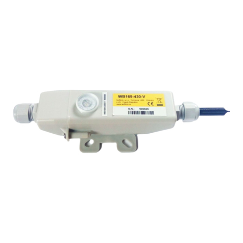
2 Appearance of the WB169-SI2 module ................................... 3
3 Setting of VIF and its effect on decoding of message ........................... 14
4”Leak” alarm function principle ....................................... 15
5”Burst” alarm function principle ...................................... 17
6 Conversion table between ”LIMIT” value and corresponding minute flow ................ 17
7”Tariff switching” function principle .................................... 19
8 Table for selection of info-message content (”mask”) ........................... 21
9 WB169-SI2 module configuration table ................................... 24
10 Basic forms of WB169-SI2 module in ”SOFTLINK Configurator” application ............. 27
11 Input/output setting form and form for setting of encryption ...................... 28
12 View of WB169-SI2 module information message received by WMBUSAN4 analyzer ......... 29
13 Encrypted and decrypted message of the WB169-SI2 module ...................... 30
14 Structure of WB169-SI2 module message with both inputs in alarm mode ............... 30
15 Structure of alarm message about the change of sensor status on the port of WB169-SI2 module . . 31
16 Structure of alarm message about the reset of WB169-SI2 module ................... 31
17 Structure of WB169-SI2 module alarm message about the ”Leak” type of alarm ............ 31
18 Set of WB169-SI2 module components with stick antenna ........................ 33
19 Detail of WB169-SI2 module PCB ..................................... 34
20 Example of ”Radar” application table ................................... 37
21 Types of sensor outputs convenient for WB169-SI2 module ....................... 38
22 Principle of ”electronic seal” sensor ..................................... 38
23 Using of position sensor for door monitoring ............................... 38
WB169-SI2 ii

1 Introduction
This document describes features, parameters and setting possibilities of the WB169-SI2 module, which is used for
reading of either consumption meters with pulse output (water meters, electrometers, gas-meters. . . ), or two-state
sensors (e.g. door contacts, flood detectors, fire detectors, electronic seals...etc.) and for radio-broadcasting of the
data from connected meters/sensors to the superior remote reading system in form of Wireless M-BUS standard
messages. The WB169-SI2 module works either in unidirectional communication mode N1, or in the bidirectional
N2 mode. In both modes the module regularly broadcasts information messages of ”User Data” type intended for
superior ”master” device. In bidirectional N2 mode it is possible to use a back channel from master device, that
can be used for transfer of ”Request” type of messages with remote configuration demands. In ”alarm mode” the
module sends ”Alarm from meter” type of messages based on the sensor status changes. These messages are sent
immediately, out of regular broadcasting interval.
1.1 Wireless M-BUS Communication Protocol
Wireless M-BUS is the communications protocol described by international standards EN 13757-4 (physical and
link layer) and EN 13757-3 (application layer), which is intended primarily for radio transmission of remote reading
values from consumption meters and sensors. Protocol Wireless M-BUS (hereinafter ”WMBUS”) is based on a
standard M-BUS definition (uses the same application layer as M-BUS standard), but is adapted for data transfer
via radio signals.
Communications via WMBUS protocol works in Master-Slave mode, where ”Master” is a collecting data device,
”Slave“ is a providing data device. Slave device could be integrated or external radio module transmitting data
from the meter/sensor. The communications protocol WMBUS defines several communication modes (simplex or
duplex). If working in simplex mode a ”Slave” device only transmits messages to ”Master” that these messages
receives. If working in ”bidirectional” mode, it is possible to use a back channel from ”Master” device to ”Slave”
device for ”Request” type of messages, that can contain e.g. request for the change of slave’s configuration.
Wireless M-BUS communications protocol partially supports repeating of the messages. If receiving from some
”Slave” device is not possible because of the low level of radio signal, the messages can be re-transmitted (repeated)
by appointed element of the radio network (repeater or slave with such functionality). Each repeated message is
marked as ”repeated message” so as not to be repeated again.
1.2 Module usage
The WB169-SI2 module can be used either for remote reading of two consumption meters with pulse output, or for
transfer of alarm messages from two two-state sensors. It is possible to combine both type of usage.
When using for remote reading of consumption meters (water meters, gas-meters, electro-meters...), up to
two meters with standard pulse (”SI”) output can be connected to the module. The meters can be of different kind,
with different quantities and units and with different conversion rates. The module continuously registers incoming
pulses (generated by meters) into its internal counters, with using of preconfigured multipliers/divisors converts
current status of each counter into the required output units (m3, kWh, MJ...) and broadcasts info-messages with
current statuses of all connected meters as Wireless M-BUS ”User Data” messages.
When using for remote monitoring of sensor statuses (door contacts, flood detectors, fire detectors, electronic
seals..), up to two two-state sensors with ”off/on” (”0/1”) outputs can be connected to the module. The sensors
can be of different kind, with different type of output and different logic of signaling. The module continuously
monitors status of each sensor and records all its changes. If the counter is switched into alarm mode, the module
immediately transmits alarm messages according to preselected rule. The module regularly broadcasts in each
info-message the number of ”0-to-1” transitions, as well as current sensor status (”0” or ”1”). If the counter is
switched into the alarm mode, the module sends ”Alarm from meter” message immediately at the change of sensor
status.
Each regular information message contains module identification, values of both counters, actual statuses of
all connected sensors in alarm mode and operational entries from embedded sensors (battery voltage, processor
temperature). Each alarm message contains only module identification and information about the actual status
of that port, on which the status was changed. Detailed information about the content and format of information
and alarm messages can be found in paragraph 3.3.
Information and alarm messages are transmitted either in open mode (without encryption), or encrypted by AES-
128 encryption key. The messages are transmitted on the 169.4 MHz frequency with data rate from 2.4 kbps to
19.2 kbps (according to used frequency channel). Messages can be received either by WB169-RFE communication
WB169-SI2 1

gateway (WMBUS Ethernet GateWay produced by SOFTLINK), or any other ”Master” device that complies with
the Wireless M-BUS EN 13757-3 / EN 13757-4 standard for 169 MHz frequency band. Principle of data transfer
from the WB169-SI2 module for both kinds of solutions is depicted in the figure 1.
Figure 1: Principle of data transfer from the WB169-SI2 module
1.3 External synchronization, tariff switching and alarm functions
TheWB169-SI2 module can be used in a wide variety of applications within different industries. The external
synchronization function is intended especially for measurement of electrical energy and gas. When using this
function, broadcasting of the module is synchronized from external source of synchronization pulses. It can be used
for measuring of energy consumption in standardized 15-minutes intervals synchronized with parallel measurement
of superior energy/gas distributor. Detailed description of this function can be found in paragraph 3.1.5 ”WMBUS’
group commands for setting of messages”.
The tariff switching function, that is also intended for energy measurement, enables distribution of input pulses
between two internal counters (”high tariff” and ”low tariff”) on the base of external control voltage of daily load
diagram system (also known as ”DSM” - demand side management). Detailed description of this function can be
found in paragraph 3.1.10 ”Description and setting of ”Tariff switching” function”.
The WB169-SI2 module enables also monitoring of operational parameters of objects by reading of sensor statuses.
Typical example of this usage is monitoring of opening/closing of overhead doors of halls, where the module can
provide information about current status of each door and measure number of open/close cycles of the doors.
Another example is monitoring of current statuses of circuit breakers or closing valves or monitoring of safety-
loops (”electronic seals”). Detailed description of special settings for sensor monitoring purposes can be found in
paragraph 3.1.9 ”Setting of sensor inputs”.
The special alarm functions ”Leak” and ”Burst” are intended for measuring of water and gas. The ”Leak”
function serves for detection of permanent minor leaks in water/gas distribution systems. The ”Burst” function
serves for detection of breakdowns in water/gas distribution systems, when some kind of accident (e.g. broken pipe)
causes huge overconsumption. Each of these functions can be configured for any port of the module. Corresponding
”Leak” and ”Burst” alarm messages are transmitted immediately after detection of the alarm status. Coding of
these alarm messages complies with M-Bus standard. Detailed description of alarm messages can be found in
paragraph refsection:struktura-zpravy ”Structure of module data messages”.
Detailed description of ”Leak” function can be found in paragraph 3.1.7 ”Description and setting of ”Leak” alarm
function”. Detailed description of ”Burst” function can be found in paragraph 3.1.8 ”Description and setting of
”Burst” alarm function”.
1.4 Bi-directional communication mode
If the WB169-SI2 module is preset for working in bi-directional communication mode N2, it could receive the
”Request” type of messages according to the Wireless M-BUS standard. These messages can be originated by
superior system or by superior ”Master” device and can contain commands for remote configuration of following
parameters:
WB169-SI2 2

- setting of transmitting power;
- setting of info-messages broadcasting period;
- correction of statuses of pulse counters - relatively (”add NN”) or absolutely (”set NN”) ,
Receiving of ”Request” type message take place always during the 500 ms long time window that starts immediately
after transmitting of regular ”User Data” info-message. During this interval the WB169-SI2 module opens its
receiver so as to be able to receive possible ”Request” message. The module confirms receiving of ”Request” by
sending of ”Acknowledgment” type of message.
Management of ”Request” type of messages must be implemented into the central application software or into the
superior ”Master” device. The messages are coded by M-Bus standard principles with short Wireless M-BUS header
with special indication of ”Request” type messages (C-byte =”53”, CI-byte = ”5A”). The message contains one
data block (with appropriate DIFE/VIFE code and required value) for each parameter, that should be remotely
changed. More detailed description of ”Request” type of message can be provided by producer of the module on
request.
1.5 Hardware features and power supplying
The module is enclosed in transparent humidity-proof plastic casing and can be used in interiors as well as in
exteriors. The casing is designed for mounting on the wall or other construction element (beam, pipe...). Module
can be treated with an additional sealing by high-adhesion silicon filling, that can ensure proof against inundation
by water (IP68 grade). If this treatment is required from the manufacturer, it must be ordered separately.
The module can be controlled and configured either by configuration cable, or wirelessly - by infra-red remote
control with using of optical converter. The module is equipped with the circular crater-shaped pit, that supports
magnetic fixing of optical converter with holding on magnet in right position.
The module is power supplied by internal battery with 13 Ah or 5.8 Ah capacity (see ordering options). If using
of 13 Ah battery, the module lifetime for 60 minutes broadcasting period is more than 8 years. If using of 5.8
Ah battery, the lifetime is up to 8 years for 120 minutes broadcasting period. Battery lifetime can be negatively
influenced by shorter broadcasting period or by storing and operation in sites with the temperatures exceeding the
recommended range for module storage and operation. Operation in bi-directional mode (N2) with using of back
channel decreases the battery lifetime by 5 %. External appearance of the WB169-SI2 module is shown in the
Figure 2.
Figure 2: Appearance of the WB169-SI2 module
1.6 Variants and ordering codes
The WB169-SI2 module is delivered in four variants with different capacity of internal battery and with different
degree of protection. There are four ordering codes for delivery of required hardware configuration of the module:
-WB169-SI2-B13 - ordering code for variant with 13 Ah battery and IP65 degree of protection
-WB169-SI2-B13/IP68 - ordering code for variant with 13 Ah battery and IP68 degree of protection
-WB169-SI2-B5 - ordering code for variant with 5.8 Ah battery and IP65 degree of protection;
-WB169-SI2-B5/IP68 - ordering code for variant with 5.8 Ah battery and IP68 degree of protection.
Together with the WB169-SI2 module also some time-tested sensors for industrial use can be ordered directly from
module’s producer (e.g. magnetic position sensor, security loop, flood detector...). Actual list of offered sensors is
available at producer’s e-shop: www.softlink.cz/obchod.
WB169-SI2 3

2 Technical parameters overview
Overview of WB169-SI2 module technical parameters is shown in the Table1below.
Table 1: Overview of WB169-SI2 module technical parameters
RF subsystem parameters
Frequency band * 169.40625 to 169.46875 MHz
Modulation * 2-GFSK, 4-GFSK
Bandwidth * 12.5 or 50 kHz
Transmitting power 500 mW
Sensitivity of back-channel receiver -109 dBm
Communication protocol Wireless M-BUS
Communication mode (by EN 13757-4) N1, N2
Transmission speed * 2400, 4800, or 19200 Baud
Antenna connector SMA female
Antenna characteristic impedance 50 Ω
Configuration interface RS232
Transmission speed 9600 Baud
Operation mode asynchronous
Transmission parameters 8 data bits, 1 stop bit, none parity
Signal level TTL/CMOS
Optical configuration interface
Transmission speed 115 200 Baud
Optical I/F specification complies with IrPHY 1.4 standard
Pulse/sensor inputs
Resistance of released contact more than 10 MΩ
Resistance of short-circuited contact less than 1 kΩ
Maximum frequency of input pulses 10 Hz
Minimum pulse length 40 ms
Range of voltage measurement in analog mode (0 ÷3,6) V
Maximum voltage on the input 3,6 V
Power supplying
3,6 V lithium battery capacity 5.8 or 13 Ah
Weight and dimensions
Length 145 mm
Width 45 mm
Height 100 mm
Weight cca 300 g
Storage and installation conditions
Installation environment (by ˇ
CSN 33 2000-3) normal AA6, AB4, A4
Operation temperature range (-20 ÷40) ◦C
Storage temperature range (0 ÷40) ◦C
Relative humidity ** 95 % (w/o condensation)
Degree of protection ** IP65 or IP68
* in reliance on selected frequency channel - see EN 13757-4, Mode N, Physical link parameters (Table 18).
** modules with additional silicon filling are waterproof with IP68 degree of protection.
WB169-SI2 4

3 Configuration of the WB169-SI2 module
Configuration parameters of the WB169-SI2 module can be displayed and changed from the common computer
(PC) by one of these methods:
- with using of ”USB-CMOS” converter and configuration cable connected to the module;
- wirelessly, with using of ”USB-IRDA” or ”BT-IRDA” converter;
-remotely, by using of bi-directional communication system.
Technique of interconnection of the module with configuration computer and general rules of configuration are
described in detail in the chapter 2 of ”Configuration of wacoSystem product family devices”, that can be
downloaded from the producer website:
www.wacosystem.com/support/
www.softlink.cz/en/documents/
The description and meaning of all configuration parameters that can be checked and changed by cable can be
found in the section 3.1 ”Setting of WB169-SI2 parameters via configuration cable”.
Description of interconnection of the converter with PC (”USB-IRDA”) or smartphone (”BT-IRDA”) and general
rules of configuration with using of optical converters are described in the chapter 3 of above mentioned manual
”Configuration of wacoSystem product family devices”. The description and meaning of the parameters that can be
changed by optical converter can be found in the section 3.2 ”Setting of parameters by using of optical converter”.
Principles and short description of communication through the Wireless M-Bus back channel can be found in
paragraph 1.4 ”Bi-directional communication mode”.
3.1 Setting of WB169-SI2 module parameters by configuration cable
3.1.1 List of module configuration parameters
List of all module configuration parameters can be displayed by entering of ”show” command and pressing of
”ENTER” key. The following list of parameters will display in the terminal window:
mon#show
----- Configuration -----
Timezone : 1
MBUS ID : 00100017
MBUS version : 5
MBUS manufacturer : SFT
MBUS medium : 7
MBUS manuf info : SI2N1
MBUS value[0] DIB : 04, VIB 13, multiplier 1, divider 1, mode falling, quick, alr: none
Leak detection periode 24 hour(s), zero periode 90 minutes
Broken pipe min. 50 pulse/10 min. during 30 minutes
MBUS value[1] DIB : 44, VIB 13, multiplier 1, divider 1, mode falling, quick, alr: none
MBUS power : 3 (20 dbm)
MBUS mode : N2
WMBUS channel : 3 - 169,43125 Mhz
Send periode : 60 min
Send mask is 3 : I1, I2
Data will be encrypted by AES
Next send : 30 min.
No. sent : 3 msg(s)
No. recv : 0 msg(s)
Conf. version : 12
SW version 0.01, date Aug 9 2019
mon#
WB169-SI2 5

3.1.2 Displaying the List of configuration commands (”HELP”)
List of all configuration commands can be displayed by entering of ”?” command and pressing of ”ENTER” key.
The following list of commands will display in the terminal window:
Help :
--- System commands ---
deb : Show or set debug level
ta : Show tasks
mb : Show mail boxes
du addr : Dump memory
rb addr : Read byte from addr
rw addr : Read word from addr
rd addr : Read dword from addr
sb addr val : Set byte on addr
sw addr val : Set word on addr
sd addr val : Set dword on addr
port : Show port [a,b,..]
show : Show info
write : Write configuration to flash
cread : Read configuration from flash
clear : Clear configuration and load defaults
--- WMBUS commands --- ---
mid : Show or set MBUS ID (0 - 99999999)
power : Show or set MBUS power (1 - 5)
manuf : Show or set MBUS manufacturer code (AAA)
info : Show or set MBUS info string (0-30 chars)
vers : Show or set MBUS version (0 - 255)
medium : Show or set MBUS medium (0 - 255)
periode : Change periode of send 0 - disable, >0 periode in minutes, <0 from input
mode : Set WMBUS mode 1 - N1, 2 - N2
chan : Set WMBUS channel, type ? for help
ekey : Set encrypt key, point ’.’ no encrypt
--- Inputs ---
val : Show or set counters values[0-1]
mul : Set multiplier of value[0-1]
div : Set divider of value[0-1]
dib : Set DIF and DIFE for value[0-1]
vib : Set VIF and VIFE for value[0-1]
det : Detection 0 - falling, 1 - rising
dmode : 0 - quick, 1 - slow
amode : 0 - disable, 1 - enable
alr : Send alarm : 0 - none, 1 - falling, 2 - rising, 3 - both
leakp : Leak detection periode in hours - 0 disabled
leakz : Leak zero periode in minutes (rounded up to ten minutes)
burstp : Burst min puls in 10 minutes
burstt : Burst check time in minutes (rounded up to ten minutes)
trf : Set tarrif 0 - off, 1 - t1 high, 2 - t1 low
--- Modem commands ---
mr : Modem receive mode 0 - off, 1 - on
mt test time : Set test on modem, 1 - TX carrier, 2 - TX sync, time is in second, default 10
ms : Get modem state
mi : Get modem info
mfreq : Set or get radio frequency correction
cfreq : Set +- frequency correction, 1 = 1Hz
...
WB169-SI2 6

...
--- Utils ---
smask : Send mask bits, 0 - I1, 1 - I2, 2 - temp. 3 - hum. ,default 3 - I1 and I2
tz : Time offset in hours
time : Show or set rtc time, set as BCD : 0x102033 is 10:20:33
date : Show or set rtc date, set as BCD : 0x171231 is 2017-12-31
uptime : Show uptime
sens : Show sensors
sendp : Send nx WMBUS messages
send : Send WMBUS message
reset : Reset device
? : Show this help
Overview of configuration parameters with short description of their meaning can be also found in table 2on the
page 23. The meaning and usage of individual commands are described below.
3.1.3 ”System commands” group for general diagnostics
Commands ””deb”, ”ta”, ”mb”, ”du addr”, ”rw addr”, ”rb addr”, ”rd addr”, ”sw addr”, ”sb addr”,
”sd addr” and ”uptime” are used for troubleshooting and repair of the device in a factory. Manufacturer
strongly recommends not to use these commands during common operation.
Other system commands ”show” (configuration statement) and ”?’ (”Help”) are described in previous part of
section3.1.
By using of ”port” command an actual setting of module ports can be displayed. This command is intended only
for module diagnostics.
3.1.4 Commands for writing of configuration and reset
The module contains two sets of configuration: operating configuration and saved configuration. At the start of the
system the module copies saved configuration to operating configuration, with which continues to work. If the user
changes configuration parameters, it does so only in operating configuration.
If the current operating configuration was not stored to FLASH memory, the module returns to the saved configura-
tion after reset. If the parameter should be changed only temporarily (for example shorten of the broadcasting period
during installation), it is not necessary to save operating configuration in FLASH memory (after the work finishing
module can be returned to normal configuration by its reset). If the parameter should be changed permanently,
there is necessary to save configuration to FLASH memory.
If operating configuration corresponds to the saved set (ie. there are no differences between commands in FLASH
and in the operating set), the module will ”report“ prompt in the format ”mon#”. If operating configuration was
changed so that it no longer matches to the saved set, the module will report prompt in the format ”cfg#”.
Every time the current configuration is saved into FLASH memory the value of the ”Configuration version” param-
eter increases by one and the prompt changes to ”mon#”. The parameter resets to zero by erasing of the FLASH
memory.
Current operating configuration can be displayed by using of ”show” command (see paragraph 3.1.1):
cfg#show
Current operating configuration can be rewrite the to FLASH memory by using of ”write” command:
cfg#write
Writing config ... OK, version 3
Reading of the configuration from FLASH memory can be done by by using of ”cread” command (for older some
modifications the command is ”read”):
cfg#cread
Reading config ... OK, version 3
WB169-SI2 7

The configuration can be erased in Flash memory by using of ”clear” command:
cfg#clear
Clearing configuration ... OK, version
This command deletes all configuration parameters from the FLASH memory, so it is necessary to set them again.
If after erasing all parameters in FLASH memory the module goes to reset, default set of parameters (configured
in the program of the device) is duplicated to FLASH memory. There is only one exception - frequency constant
keeps the actual value also after cleaning of FLASH memory by ”clean” command.
This command is recommended to use only by users with good knowledge of the system or after
consultaion with the manufacturer.
The module reset can be performed by using of ”reset” command.
3.1.5 ”WMBUS” group commands for setting of messages
This group of commands serves for setting of Wireless M-BUS addressing of the WB169-SI2 module and for setting
of broadcasting parameters. There are following command:
mid setting of device fabrication number (”M-BUS ID” – range 0 to 99999999)
manuf setting of manufacturer code (”Manufacturer” - supplement of M-BUS address)
vers setting of ”addressing version” (”Version” - supplement of M-BUS address)
medium setting of media code (”Medium” - supplement of M-BUS address)
info setting device name
periode setting of regular messages broadcasting period
power setting of transmitting power (mW)
mode setting of communication mode (1 - N1 mode, 2 - N2 mode)
chan setting of frequency channel (choice from 7 options)
ekey setting of encryption key (”.” - encryption disabled)
Variable ”M-BUS ID” is a serial number of the device in M-Bus standard identification system. The address is
”read only” type for the WB169-SI2 module and cannot be changed. Assigned serial number of the module can be
displayed by”mid” command (without parameter):
cfg#mid
MBUS ID : 00112233
cfg#
Variable ”Manufacturer” is an international code of device producer according to the M-Bus standard. The code
is ”read only” type for the WB169-SI2 module, its value is ”SFT” (Softlink) and it cannot be changed. Assigned
manufacturer code can be displayed by”manuf” command (without parameter):
cfg#manuf
MBUS manufacturer : SFT
cfg#
Variable ”Version” is number of addressing version according to the M-Bus standard (each type and modification
of the device could have its own line of serial numbers). The code is ”read only” type for the WB169-SI2 module
and cannot be changed. Assigned version number can be displayed by ”vers” command (without parameter):
cfg#vers
MBUS version : 101
cfg#
Variable ”Medium” is an international code of measured medium (water, energy, physical quantity..) according
to the M-Bus standard. The variable is editable and it is factory preset to 07 (”Water”). Current setting of the
medium value can be displayed by ”medium” command (without parameter). Medium parameter can be changed
by entering of required code of medium according to M-Bus standard (range: 0 to 255).
Example of medium code setting to ”02” value (electricity):
WB169-SI2 8

cfg#medium
MBUS medium : 7
cfg#medium2
MBUS medium changed from 7 to 2
cfg#
Note: The full identification of the device in M-Bus standard systems is done by combination of four ID components:
”M-BUS ID”, ”Manufacturer”, ”Version” and ”Medium”. This combination must be unambiguous that means
there cannot exist two M-Bus devices worldwide, that have the same combination of all these parameters. If fixed
configuration of the address components used, producer of the device is responsible for unique setting of ”read
only” address components for each device. If M-Bus address components are configurable, operator of the M-Bus
system can use serial number of connected meter in combining with its type, subtype and manufacturer. Using of
”independent” addressing line is possible only in that case, if the operator of the system owns its M-Bus manufacturer
code and can assure that the identification of all operated devices under his code will be unique
”Info” command can be used for setting of device name that is a part of each broadcasted message (see para-
graph 3.3). The parameter is preset from the factory to ”SI2” value. By using of ”info” command (without
parameter) an actual value of the name can be displayed. The device name can be set by entering of any string of
characters after ”info” command.
Example of displaying, setting and follow-up checking of the device name:
cfg#info
MBUS manuf info : ’ABC’
cfg#info XYZ
Change MBUS manuf info from : ’ABC’ to : ’XYZ’
cfg#info
MBUS manuf info : ’XYZ’
cfg#
Maximum length of the string is 29 characters. The only basic set of characters can be used (without diacritics).
It is not recommended to change this parameter.
”Periode” command serves for setting of broadcasting period of regular info messages. The value of the parameter
is factory preset to 60 minutes. Current value can be checked by ”periode” command (without parameter).
Broadcasting period can be changed by entering of required number of minutes after ”periode” command.
Example of displaying, setting and follow-up checking of broadcasting period:
cfg#periode
Periode is 60 min.
cfg#periode 30
Periode changed from 60 to 30 min.
cfg#periode
Periode is 30 min.
cfg#
The module enables also an external synchronization of its broadcasting from external source of synchro-
nization pulses. For this purpose any of module ports can be assigned as ”synchronizing” by using of ”Periode
-X” command, where ”X” is number of assigned port.
Example of setting of port No. 2 to ”synchronization” mode:
cfg#periode -2
Periode changed from 60 min. to I2
mon#
If using of this setting, the process of transmitting of info message launch after each falling edge of the synchro-
nization pulse is received on the synchronizing port. There is a protective interval of 1 minute implemented in the
system, so the broadcasting period could be at least 1 minute. Requirements for the synchronization pulses are the
same, as for metering pulses.
This feature is important in that case, if the measurement and broadcasting of measured values should be synchronized
with some other process. Typical example is measurement of electrical energy in 15-minutes intervals, that must be
WB169-SI2 9

synchronized with measuring intervals of superior part of the electrical grid. In this case it is necessary to bring
15-minutes synchro-signal (e.g. from electrometer with such kind of output) to the synchronizing port.
WARNING: If there are synchronization pulses with inverse logic connected, it could cause a slight decreasing of
battery lifetime (up to 5 %). ”Inverse logic” means that the input is permanently short-circuited and only during
short time pulses it is released.
Regular broadcasting can be disabled by entering of ”periode” command with ”0” parameter. Example:
cfg#periode 0
Periode changed from 60 min. to disabled
mon#
Group of ”power” (transmitting power), ”chan” (frequency channel), ”mode” (communication mode) and
”ekey” (encryption key) commands is intended for setting of module RF-subsystem parameters.
The command ”Power” is used for adjusting of the module broadcasting power. Factory setting is 100 mW
(average power). Actual value of the power can be displayed by using of the ”power” command without parameter.
Transmitting power can be set-up by entering of the number of power level. There are five levels available:
- value ”1” for transmitting power 14 dBm (25 mW)
- value ”2” for transmitting power 17 dBm (50 mW)
- value ”3” for transmitting power 20 dBm (100 mW)
- value ”4” for transmitting power 24 dBm (250 mW)
- value ”5” for transmitting power 27 dBm (500 mW)
An example of checking, setting and re-checking of transmitting power:
cfg#power
MBUS power : 3 (20 dBm)
cfg#power 5
MBUS power changed from 3 to 5 (27 dbm)
cfg#power
MBUS power : 5 (27 dBm)
cfg#
The command ”Communication mode” is used for selecting of the module’s communication mode. Factory
setting is N1 (unidirectional), or N2 (bidirectional), actual setting can be checked by using of ”mode“ command
without parameter. Change of mode can be done by entering of desired option as a parameter of the command.
Communication modes are defined by the Wireless M-BUS standard, accurate choice of relevant communication
modes of the module is stated in the line ”mode” of ”Help” summary (see the paragraph 3.1).
An example of checking, setting and re-checking of communication mode:
cfg#mode
Mode N1
cfg#mode 2
CC1120 state 0x0f, marcstate 65, fifo tx 0, rx 0
Mode changed from 1 to 2
cfg#mode
Mode N2
cfg#
The command ”Frequency channel” is used for selecting of the module’s radio frequency channel. Frequency
channels for the particular frequency bands are defined by the Wireless M-BUS standard. Actual setting can be
checked by using of ”chan“ command without parameter. Change of channel can be done by entering of desired
option as a parameter of the command. Accurate choice of relevant broacasting communication modes of the module
is stated in a line ”mode” in ”Help” summary (see the paragraph 3.1.2).
An example of checking, setting, saving and re-checking of frequency channel:
WB169-SI2 10

cfg#chan
Help :
1 - chan 1a (169.40625 Mhz), 4.8 kbps
2 - chan 1b (169.41875 Mhz), 4.8 kbps
* 3 - chan 2a (169.43125 Mhz), 2.4 kbps
4 - chan 2b (169.44375 Mhz), 2.4 kbps
5 - chan 3a (169.45625 Mhz), 4.8 kbps
6 - chan 3b (169.46875 Mhz), 4.8 kbps
7 - chan 3g (169.43750 Mhz), 19.2 kbps
cfg#chan 1
Channel changed from 3 to 1 : chan 1a (169.40625 Mhz), 4.8 kbps
CC1120 state 0x0f, marcstate 65, fifo tx 0, rx 0
cfg#chan
Help :
* 1 - chan 1a (169.40625 Mhz), 4.8 kbps
2 - chan 1b (169.41875 Mhz), 4.8 kbps
3 - chan 2a (169.43125 Mhz), 2.4 kbps
...
The command ”Encryption key” is used for setting of the encryption key for an encryption of transmitted
messages by using of AES-128 key. The encryption key of 16 bytes length is entered by using of ”ekey“ command,
followed by the string of 16 bytes that can be entered in a decimal or hexadecimal format (see examples).
An example of insertion of the encryption key in hexadecimal format:
cfg#ekey 0x1a 0x2b 0x3c 0x4d 0x5e 0x6f 0xa1 0xb2 0xc3 0xd4 0xe5 0xf6 0x77 0x88 0x99 0xaf
Setting encyption key : 1a 2b 3c 4d 5e 6f a1 b2 c3 d4 e5 f6 77 88 99 af
cfg#
An example of insertion of the encryption key in decimal format:
cfg#ekey42 53 159 188 255 138 241 202 136 21 98 147 235 15 145 136
Setting encyption key : 2a 35 9f bc ff 8a f1 ca 88 15 62 93 eb 0f 91 88
cfg#
If the encryption key is set to the module’s configuration, an information ”Data will be encrypted by AES”
displays in the list of configuration parameters (see chapter 3.1.1)
Encryption can be switched off by setting of ”.” (dot) parameter after the ”ekey“ command:
cfg#ekey.
Encyption disabling
cfg#
In this case an information ”Data will be unencrypted” appears in the list of configuration parameters.
3.1.6 ”Inputs” group parameters
This group of parameters and commands enables setting of internal pulse registers (counters) and setting of output
values of the module.
The WB169-SI2 module is equipped with two inputs (port 1 and 2), that are connected to the corresponding pulse
counters (index 0 and 1). Each counter increases its value up one unit each time it receives pulse from a consumption
meter connected to its port. Below listed commands are used for settings of the initial counter values and constants
(multipliers, divisors) that can be used for adjusting of the output statuses to required values, and also for setting
of auxiliary ”DIF” and ”VIF” M-Bus codes that enable correct decoding of measured values (especially correct
decoding of measuring units).
Each input can be switched to so called ”alarm mode”, in which after each change of input value the counter
only changes its status (goes from ”0” to ”1” or vice versa) and the module transmits the message immediately
with the change of status. Thus the module can read and transfer status information from binary sensors (e.g.
WB169-SI2 11

door contacts, flood detectors..). Detailed description of setting of inputs in alarm mode can be found in the
paragraph 3.1.9 ”Settings of sensor inputs”.
Setting of pulse inputs can be performed with using of following commands:
val[index] initial counter value setting
mul[index] setting of multiplier (output value = status * multiplier)
div[index] setting of divisor (output value = status / divisor)
dib[index] setting of DIF value (= coding method information)
vib[index] setting of VIF value (= measuring unit information)
det[index] setting of trigger edge (0 - falling edge, 1 - rising edge)
dmode[index] setting of pulse input mode (0 - quick pulses, 1 - slow pulses)
amode[index] switching of analog mode (for WB169-SI2 not used)
alr[index] setting of alarm mode (sensor input setting)
alcok[index] specification of alarm mode for ”OK” status (sensor input setting)
alcerr[index] specification of alarm mode for ”Error” status (sensor input setting)
leakp[index] period of leak detection setting (see ”leak” function)
leakz[index] zero interval of leak detection setting (see ”leak” function)
burstp[index] burst alarm limit setting (see ”burst” function)
burstt[index] burst measuring interval setting (see ”burst” function)
trf[index] setting of second port to tariff switching mode (see ”tariff” function)
By using of ”val[index]” command an initial (or actual) value of the counter can be set. After the value is
setup, it increases from this value with each new-coming pulse. Actual counter value can be displayed by using of
”val[index]” command (without parameter). Counter status can be set to required value by using of ”val[index]”
command followed by required whole number (integer).
Example of setting port No 1 (index=0) counter to ”1892” value and follow-up checking of correctness of the
configuration:
cfg#val0 1892
Value[0] changed from 1565252980 to 1892
cfg#val0
Value[0] : 1892 * 1 / 1 -> 1892
cfg#
It is evident from the example, that when checking of current status by ”val[index]” command, the system displays
not only current status value, but also current settings of multiplier and divisor and output value after multiply-
ing/dividing.
By using of ”mul[index]” and ”div[index]” commands a value of multiplier and divisor can be set to the
counter. Default setting of both values is ”1”. If it is necessary to adjust the counter value by some coefficient,
enter convenient combination of multiplier and divisor as shown in example below.
Actual value of multiplier and divisor can be displayed by using of ”val[index]”, ”mul[index]” or ”div[index]”
commands (without parameter) as shown in the example:
cfg#mul0
Multiplier[0] = 1
cfg#div0
Divider[0] = 1
cfg#
Multiplier and divisor setting example:
Watermeter generates measuring pulses after each 50 litres of consumed water. To indicate water consumption in
m3, it is necessary to adjust the original counter value by using of multiplier and divisor as shown in the example:
50 litres = 0.05 m3, so to convert the value to m3, it must be multiplied by 5/100.
It could be done by setting of multiplier to ”5” and divisor to ”100” - see example:
WB169-SI2 12

cfg#mul0 5
Multiplier[0] = 5
cfg#div0 100
Divider[0] = 100
cfg#val0
Value[0] : 2000 * 5 / 100 -> 100
cfg#
From the display of summary shown in the last sequence of commands it is evident that current status value (2000)
will be interpreted as output value 100 (m3). As one unit of the counter represents 50 litres, output value of the
counter is: 2000*50 = 100 000 litres = 100 m3.
By using of ”dib[index]” command a value of DIF code could be set. The DIF code describes character of
the variable, number of ”storage” and format of data field according to the M-Bus standard. Default setting of DIF
parameters of the module counters is as follows:
counter:”0” DIF = 04 00 (instant value, 32-bit integer, storage No ”0”)
counter:”1” DIF = 44 00 (instant value, 32-bit integer, storage No ”1”)
Warning: It is not recommended to make changes of DIF parameter.
By using of ”vib[index]” command a value of VIF code could be set. The VIF code describes the kind of
measured quantity (e.g. volume, temperature, voltage...) and the measuring unit (including multiplier) in which
the value is presented (e.g. m3,◦C, mV, kWh...) according to the M-Bus standard. Default setting of VIF param-
eter of all counters is:
VIF = ”13” (quantity: ”Volume”, measuring unit: 10−3 * m3)
It means that with using of default setting the information message contains value of measured volume in thousandth
of m3, i.e. in litres. If a watermeter is connected to the module with default setting of VIF code, it is necessary
to check out how many litres represent one measuring pulse and setup multiplier and divisor values so as to get
output value in litres. If, as an example, the watermeter generates measuring pulse after each 10 litres of volume,
it is necessary to set multiplier to value ”10”.
If it is needed to get volume in other units than litres (e.g. in m3), or other quantity than volume is measured (e.g.
electrical work in kWh), it is necessary to adjust values of multiplier and divisor to get result in required units as
well as setup correct VIF value to ensure correct presentation of the unit in auxiliary information.
Examples of settings of VIF code
Example of VIF setting in case the water consumption is presented in m3:
Setup values of multiplier and divisor in order to convert output value into ”m3” units (see example of multi-
plier/divisor setting above). Calculate value of VIF code for ”m3” units as follows:
”Codes for Value Information Field (VIF)” table of M-Bus standard designates for ”Volume” quantity ”0001 0nnn”
code, where the result is in 10(nnn −6) m3units. It means that the last three bits of code determine value of unit
multiplier. To get result in litres it is necessary to use multiplier 10(−3) (because 1 liter = 0.001 m3), so that the
value of last three bits must be ’3” (nnn=3). In this case the multiplier is 10(3−6), that is 10(−3) = 0.001). It
means that the correct VIF code for volume in litres is ”0001 0011”, because decadic value nnn=3 converted into
binary code means ”011” value. Conversion of binary ”00010011” value into decadic transcription gives number
”13”, what is default setting of VIF parameter.
To present the measured volume in m3, it is necessary to put multiplier ”1” before ”m3” value. For this case the
value of ”nnn’ must be ”6” (so that the multiplier value is 10(6−6), that is 10(0) = 1). The correct value of VIF
code for volume in m3is ”0001 0110” (because decadic value nnn=6 converted into binary code means ”110” value).
Conversion of binary ”00010110” value into decadic transcription gives number ”16”, what is required setting of
VIF parameter.
Parameter VIF can be setup to ”16” value as follows:
cfg#vib0
VIB[0] : 13
cfg#vib0 0x16
Set VIB[0] : 16
VIB[0] : 16
cfg#
WB169-SI2 13

The same input of VIF parameter could be entered also in decadic form as follows:
cfg#vib0 22
Set VIB[0] : 16
Example of VIF code setting in case the variable is electric work in kWh:
”Codes for Value Information Field (VIF)” table of M-Bus standard designates for ”Energy” quantity ”0000 0nnn”
code, where the result is in 10(nnn −3) Wh units. The last three bits of code determine unit multiplier. To get
result in kWh it is necessary to use multiplier 10(3) (because 1 kWh = 1000 Wh), so that the value of nnn=6 (in this
case the value of multiplier is 10(6−3), that is 10(3) = 1000). It means that the correct VIF code for electric work
in kWh is ”0000 0110”, because decadic value nnn=6 converted into binary code means ”110” value. Conversion of
binary ”00000110” value into decadic transcription gives number ”06”, what is required setting of VIF parameter.
Parameter VIF can be setup to ”06” value as follows:
cfg#vib1 0x06
Set VIB[1] : 06
Above described setting of VIF parameter reflects in decoded message as seen in the figure 3.
Figure 3: Setting of VIF and its effect on decoding of message
In the figure 3can be seen a decoded message of the WB169-SI2 module, where there is the same ”1000” multiplier
value and the same ”1” divisor value set up on both counters.
It is clear from the picture that:
- counter value ”0” with preset ”1 x m3” unit is presented as ”1000 m3”
- counter value ”1” with preset ”1000 x Wh” unit is presented as ”1000 000 Wh”
By using of ”det[index]” command a trigger edge of the counter could be chosen. If it is preset to ”0” option
(default setting) the value of counter will increase with falling edge of incoming pulse (i.e. when the mechanical
contact is short-circuited, or when an electronic pulse generator goes from ”1” to ”0”). If it is preset to ”1” option,
the value of counter will increase with rising edge of incoming pulse (i.e. when the mechanical contact is released,
or when an electronic pulse generator goes from ”0” to ”1”). Actual value of trigger edge setting can be displayed
by using of ”det[index]” command (without parameter).
Example of setting of trigger edge for port No 1 (index=0) to ”1” option (rising edge) and follow-up checking of
trigger edge setting of all ports:
mon#det0 1
Det[0] = 1 - rising
cfg#det
Det[0] = 1 - rising
Det[1] = 0 - falling
Det[2] = 0 - falling
Det[3] = 0 - falling
cfg#
By using of ”dmode[index]” command a smoothening (equalizing) filter of pulse input could be involved or
disconnected. If it is preset to ”0” option (default setting) the equalizing filter is switched off and the input is preset
for detecting of high frequency (quick) pulses. If it is preset to ”1” option, the equalizing filter that can suppress
disturbing pulses on the input is switched on. This setting could be used if there are some parasitic pulses on the
pulse input (e.g. if the input wire is too long), but using of this filter is restricted only for sensor input, or for
detecting of slow pulses with maximum frequency of 2 Hz (minimum length of pulse is 250 ms).
WB169-SI2 14

Example of setting of port No 1 (index=0) mode to ”1” option with involved equalizing filter (slow pulses):
cfg#dmode1 1
Mode[1] = 1 - slow
cfg#
Detailed description of ”Leak” alarm function can be found in the paragraph 3.1.7 below. Detailed description of
”Burst” alarm function can be found in the paragraph 3.1.8 below. Detailed description of sensor input settings can
be found in the paragraph 3.1.9 ”Setting of sensor inputs” below. Detailed description of ”tariff switching” function
can be found in the paragraph 3.1.10 below.
3.1.7 Description and setting of ”Leak” alarm function
”Leak” function is used for detection of such situations in the consumption of gas, water or other liquids, when
there are permanent low-quantity losses caused by minor leaks in the distribution system. In view of the fact that
remote reading systems don’t record consumption continuously but in some steps (usually given by full turn of its
measuring disk), it could take quite long time until the trouble is discovered.
”Leak” function is based on the common pattern that during the normal long-term (e.g. day, week) operation there
are usually some regular time intervals, when the consumption is in its ”idle” status, because the gas/liquid is not
consumed from natural reasons (e.g. during the night, or out of working hours). In these idle time intervals the
consumption should be zero volume. If there are any leaks, time intervals with zero consumption practically either
do not occur, or there are only short intervals caused by discontinuity of measuring system (e.g. if one metering
pulse represents 100 litres, minor leak could become evident even after several hours, when such quantity will leak).
.
”Leak” function principle is shown in the figure 4. When setting of ”Leak” alarm function the length of detection
period must be entered by setting of ”Leak Detection Period” parameter. After expiration of this period the
system evaluates whether during this period at least one time occurred the situation, when the consumption was
in zero level during preset time interval (entered by ”Zero Period” parameter). If there is no leakage, it is highly
probable that zero consumption period occur at least once during the period and system evaluates the period as
”no alarm” status (see upper part of the figure 4). But if there is no one interval with zero consumption registered
during whole detection period, module transmits to superior system ”Leak” alarm message (see lower part of the
figure 4).
”Leak” function can be activated for chosen port by using of ”leakp[index]” command that defines the length of
detection period (”Leak detection period” parameter) in hours. By using of ”leakz[index]” command setup
concurrently for the same port the length of zero consumption interval (”Zero period” parameter) in minutes.
If one of these parameters is set to ”0” for some port, ”Leak” function is deactivated for that port.
Figure 4: ”Leak” alarm function principle
WB169-SI2 15

Example of setting ”Leak detection period” parameter for port No 1 (index ”0”) to 24 hours value:
cfg#leakp 0 24
Value[0] changed from 0 to 24
cfg#
Detection period can be set in range of 1 - 1090 hours, typical setting is 24 hours (daily operational cycle), or 168
hours (weekly operational cycle). Detection period starts running from module restart, or from the moment when
the parameter is changed. Alarm message is sent at the end of detection period.
Example of setting ”Zero period” parameter for port No 1 (index ”0”) to 60 minutes value:
cfg#leakz 0 90
Value[0] changed from 0 to 90
cfg#
Zero consumption period can be set in range of 1 - 1090 minutes with precision of ten minutes (rounded to tens of
minutes, e.g. 10, 20, 30...). If the command is entered with any other value (e.g. 36 minutes) the system will store
rounded value anyway (in this case 40 minutes). General principle is that setting of zero period parameter to longer
values means that the detection is more sensitive (it is capable to detect smaller leaks), but it is also less reliable
with higher probability to produce false alarm due to real consumption caused by random changes of operating
cycle (e.g. if somebody was held up at work few hours longer).
Setting of ”Leak” alarm function parameters appears in the List of configuration parameters (”show” command),
in the section of the particular port:
MBUS value[0] DIB : 04 00, VIB : 13 00 ,multiplier 1, divider 1
Leak detection period 24 hour(s), zero period 90 minutes
Structure of alarm message of ”Leak” type is described in the paragraph 3.3.2 ”Alarm message”.
3.1.8 Description and setting of ”Burst” alarm function
”Burst” function is used for detection of such situations in the consumption of gas, water or other liquids, when the
burst consumption caused by broken pipe (or similar fatal failure of distribution system) occurs. If the consumption
of liquid/gas is abnormally huge for some period of time, the module transmits to the superior system alarm message
of ”7” type (”Burst”).
”Burst” function principle is shown in the figure 5.”Burst” alarm function is set-up by entering of the burst
consumption limit (”burstp[index]” command), that means the limit over which the consumption is considered
as abnormal, and entering of ”Burst Check Time” period (”burstt[index]” command) that means the minimum
time period during which the consumption must be permanently over limit to detect the ”Burst” alarm.
In view of the fact that different meters connected to the module could have different conversion rate of volume per
measuring pulse, consumption limit is delimited universally as number of registered pulses per 10 minutes
time period. Conversion table between ”pulses per 10 minutes” and ”consumption per minute” for frequently
used conversion rates of watermeters is available in the figure 6.
”Burst” function can be activated for chosen port by using of ”burstp[index”] command that defines required
consumption limit in number of pulses per 10 minutes period. By using of ”burstt[index]” command setup
concurrently for the same port minimum duration of abnormal consumption (”Burst Check Time”) in minutes. If
one of these parameters is set to ”0” for some port, ”Burst” function is deactivated for that port.
Example of setting ”LIMIT” parameter for port No 1 (index ”0”) to 15 pulses per 10 minutes:
cfg#burstp 0 15
Value[0] changed from 0 to 15
cfg#
Consumption limit alarm value can be set in practically unlimited range (1 to 65535 pulses per 10 minutes).
Example of setting ”Burst Check Time” parameter for port No 1 (index ”0”) to 40 minutes value:
WB169-SI2 16

Figure 5: ”Burst” alarm function principle
Figure 6: Conversion table between ”LIMIT” value and corresponding minute flow
cfg#burstt 0 40
Value[0] changed from 0 to 40
cfg#
Minimum duration of abnormal consumption (”Burst Check Time”) can be set up in range 1 - 1090 minutes with
precision of ten minutes (rounded to tens of minutes, e.g. 10, 20, 30...). If the command is entered with any other
value (e.g. 36 minutes) the system will store rounded value anyway (in this case 40 minutes). General principle
is that setting of Burst Check Time parameter to longer values means that the detection is more reliable, with
lower probability to produce false alarm due to random changes in normal operation (e.g. during filling a tank with
water), but in the same time it will prolong the response time between the breakdown and sending of alarm.
Setting of ”Burst” alarm function parameters appears in the List of configuration parameters - in the section of the
particular port:
MBUS value[0] DIB : 04 00, VIB : 13 00 ,multiplier 1, divider 1
Broken pipe min. 15 pulse/10 min. during 40 minutes
Structure of ”Burst” alarm message is described in the paragraph 3.3.2 ”Alarm message”.
3.1.9 Setting of sensor inputs
Any two-state sensors of ”on/off” (0/1) type with contact, relay, or electronic binary output (e.g. door contacts,
flood detectors, fire detectors, electronic seals...etc.) can be connected to any WB169-SI2 module port. If the port
is not preset to ”alarm mode”, the module only stores number of 0/1 transitions of the sensor into the counter and
WB169-SI2 17
Table of contents
Other SOFTLINK Conference System manuals
Popular Conference System manuals by other brands

Microchip Technology
Microchip Technology 3DTouchPad user guide

Williams AV
Williams AV BluePOD Conference Mate user manual

Edis
Edis CS17-1 user manual
TANDBERG
TANDBERG Maestro MXP Installation sheet
Danish Interpretation Systems
Danish Interpretation Systems DCS 6000 user manual

Polycom
Polycom Trio Series manual

