SOFTLINK WB169-430-V User manual


Contents
1 Introduction 1
1.1 Wireless M-BUS Communication Protocol ................................ 1
1.2 Module usage ................................................. 1
1.3 Hardware features and power supplying .................................. 2
2 Technical parameters overview 3
3 Configuration of the WB169-430-V module 4
3.1 Setting of WB169-430-V module parameters by configuration cable ................... 4
3.1.1 List of WB169-430-V module configuration parameters and commands ............. 4
3.1.2 ”System commands” group for general diagnostics ........................ 6
3.1.3 Commands for writing of configuration and reset ......................... 6
3.1.4 Commands of ”433 Commands” group for setting of receiving system of watermeter messages 7
3.1.5 Commands of ”169 Commands” group for setting of 169 MHz network communication .... 9
3.1.6 Commands for setting of watermeter reading ........................... 10
3.1.7 Commands of ”Utils” group for setting of module basic functions ................ 14
3.1.8 Displaying of other operational entries in the list of parameters ................. 17
3.2 Setting of parameters by using of optical converter ............................ 17
3.3 Remote setting of module parameters through reverse channel ...................... 21
3.3.1 Overview of module configuration parameters ........................... 22
3.4 Structure of module data messages ..................................... 23
3.4.1 Iinformation message ......................................... 23
3.4.2 Alarm message ............................................ 24
3.4.3 Setting messages ........................................... 25
4 Operational conditions 28
4.1 General Operation Risks ........................................... 28
4.1.1 Risk of mechanical and/or electric damage ............................. 28
4.1.2 Risk of premature battery discharge ................................ 28
4.1.3 Risk of damage by excessive humidity ............................... 28
4.2 The condition of modules on delivery .................................... 29
4.3 Modules storage ............................................... 29
4.4 Safety precautions .............................................. 29
4.5 Environmental protection and recycling .................................. 29
4.6 WB169-430-V module installation ..................................... 29
4.7 Module and meter replacement ....................................... 32
4.8 Module dismantling ............................................. 32
4.9 Functional check of the module ....................................... 33
4.10 Operation of the WB169-430-V module .................................. 33
5 Troubleshooting 34
5.1 Possible causes of module failures ...................................... 34
5.1.1 Power supplying failures ....................................... 34
5.1.2 System failures ............................................ 34
5.1.3 Transmitter and receiver failures .................................. 34
5.1.4 Failures of communication with watermeters ........................... 35
5.2 Troubleshooting procedure .......................................... 35
6 Additional information 36
List of Tables
1 Overview of WB169-430-V module technical parameters ......................... 3
2 Overview of WB169-430-V module configuration parameters ....................... 22
3 Structure of Wireless M-BUS message header of the WB169-430-V module .............. 23
4 Description of variables of WB169-430-V module info-message data block ............... 23
5 Table of variables in setting messages of WB169-430-V module ..................... 26
WB169-430-V i

List of Figures
1 View of the WB169-430-V module ..................................... 2
2 WB169-430-V module configuration table ................................. 18
3 Configuration forms of WB169-430-V module in ”SOFTLINK Configurator” application ....... 20
4 Setting of meter reading list ......................................... 20
5 View of WB169-430-V module information message received by WMBUSAN4 analyzer ........ 24
6 Encrypted and decrypted message of the WB169-430-V module ..................... 24
7 Structure of alarm message about the reset of WB169-430-V module .................. 25
8 Structure of message with the content of ”Radar” table ......................... 26
9 Structure of message with the content of ”SID” table ........................... 27
10 Set of WB169-430-V module components with rod antenna ....................... 30
11 Detail of WB169-430-V module PCB .................................... 30
12 Example of ”Radar” application table ................................... 33
WB169-430-V ii

1 Introduction
This document describes features, parameters and setting possibilities of the WB169-430-V module, which is used
either for remote reading of iPERL series watermeters by Sensus equipped with 433 MHz data transmitter, or other
watermeters (*) of the ”smart” category, equipped with an 433 MHz transmitter working in Wireless M-Bus format.
The module receives messages from watermeters and broadcasts the read data to the superior Automatic Meter
Reading (AMR) system n form of 169 MHz Wireless M-Bus standard messages.
(*) Although the module is primarily intended for reading watermeters, it can also be used for reading of any other
consumption meters or sensors that send messages in 433 MHz Wireless M-Bus format.
1.1 Wireless M-BUS Communication Protocol
Wireless M-BUS is the communications protocol described by international standards EN 13757-4 (physical and
link layer) and EN 13757-3 (application layer), which is intended primarily for radio transmission of remote reading
values from consumption meters and sensors. Protocol Wireless M-BUS (hereinafter ”WMBUS”) is based on a
standard M-BUS definition (uses the same application layer as M-BUS standard), but is adapted for data transfer
via radio signals.
Communications via WMBUS protocol works in Master-Slave mode, where ”Master” is a collecting data device,
”Slave“ is a providing data device. Slave device could be integrated or external radio module transmitting data
from the meter/sensor. The communications protocol WMBUS defines several communication modes (simplex or
duplex). If working in simplex mode a ”Slave” device only transmits messages to ”Master” that these messages
receives. If working in ”bidirectional” mode, it is possible to use a reverse channel from ”Master” device to ”Slave”
device for ”Request” type of messages, that can contain e.g. request for the change of slave’s configuration.
Wireless M-BUS communications protocol partially supports repeating of the messages. If receiving from some
”Slave” device is not possible because of the low level of radio signal, the messages can be re-transmitted (repeated)
by appointed element of the radio network (repeater or slave with such functionality). Each repeated message is
marked as ”repeated message” so as not to be repeated again.
1.2 Module usage
The WB169-430-V module can be used as local communication gateway for remote reading of Sensus iPERL-
series watermeters, or other ”smart” watermeters with integrated Wireless M-Bus transmitters in the 433 MHz
band. The module receives regular radio messages with readings from watermeters within its radio-reach and
stores the readings to its memory. In pre-defined intervals the module broadcasts aggregate of received data to
the superior remote reading system (AMR) in form of Wireless M-Bus radio-messages in 169 MHz frequency band
(”INFO” messages).
The WB169-430-V module can by used for remote reading up to 20 watermeters placed in its radio-reach (that
is up to hundreds meters). Each watermeter transmits the messages with a short fixed period (e.g. iPERL every
15 seconds). The module receives data from watermeters in regular ”receiving windows”, that are opened with
preset transmitting period (e.g. every 120 minutes). Received data from each receiving window are stored into the
module memory. Immediately after closing of the receiving window the module broadcasts received data from all
watermeters to the superior system in one Wireless M-Bus message.
Each module has its table of read watermeters, where there are IDs (serial numbers) of meters that should be
read by the module. If there are other watermeters in the reach, their messages are ignored. The module supports
receiving and transmitting of messages either in open mode, or in encrypted mode. The module allows forwarding
of original alarm statuses (”flags”) from watermeters together with normal readings, or conversion of ”flags” into
the wacoSystem alarm messages, that are sent immediately.
Content of INFO-messages is configurable. The messages contain identification and current statuses of module
parameters (uptime, battery voltage, processor temperature..), list of read watermeters and current values of its
counters. The messages are broadcasted either in open mode (without encryption), or encrypted by AES-128
encryption key. The messages are transmitted on the 169.4 MHz frequency with data rate from 2.4 kbps to 19.2
kbps (according to used frequency channel). Messages can be received either by WB169-RFE communication
gateway (WMBUS Ethernet GateWay produced by SOFTLINK), or any other ”Master” device that complies with
the Wireless M-BUS EN 13757-3 / EN 13757-4 standard for 169 MHz frequency band.
The WB169-430-V module supports bi-directional communication and it is able to receive commands in Wireless
M-Bus format from the 169 MHz network. These messages can be used for setting of module parameters from the
remote server.
WB169-430-V 1
1.3 Hardware features and power supplying
The module is enclosed in humidity-proof plastic casing with IP65 degree of protection and can be used in interiors
as well as in exteriors. The casing is designed for mounting on the wall or other construction element (beam,
pipe...). Module can be treated with an additional sealing by high-adhesion silicon filling, that can ensure proof
against inundation by water (IP68 grade). If this treatment is required from the manufacturer, it must be ordered
separately.
The module is power supplied by internal battery with up to 8 years lifetime for frequency of 6 broadcastings per
day. Battery lifetime can be negatively influenced by shorter broadcasting period, or by storing and operation in
sites with the temperatures exceeding the recommended range.
The module can be controlled and configured either by configuration cable, or wirelessly, by infra-red optical
converter. The module is equipped with the special circular aperture (”peephole”) for magnetic fixing of the
optical converter. The module can be also configured remotely, with using of reverse channel of bi-directional
communication.
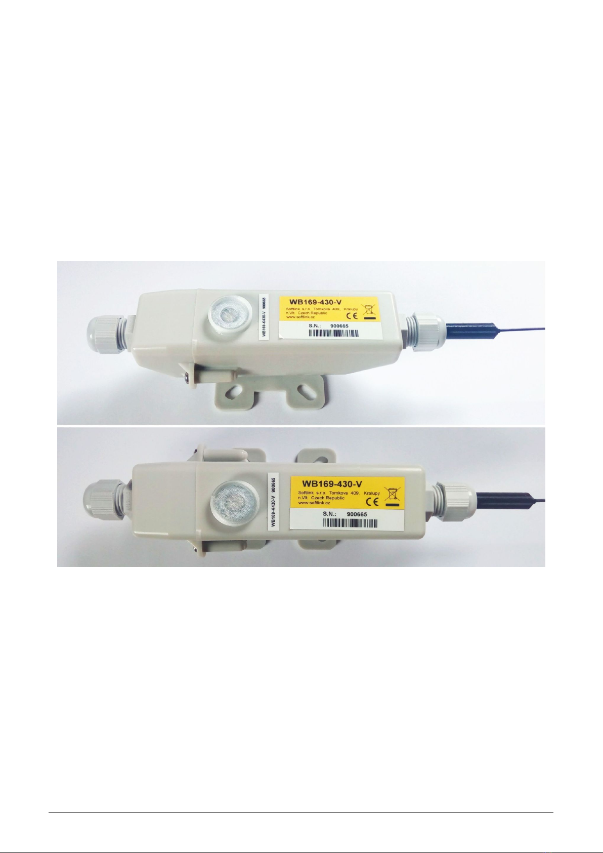
External appearance of the WB169-430-V module is shown in the figure 1.
Figure 1: View of the WB169-430-V module
WB169-430-V 2

2 Technical parameters overview
Overview of WB169-430-V module technical parameters is shown in the Table1below.
Table 1: Overview of WB169-430-V module technical parameters
RF subsystem parameters
Frequency band * 169.40625 to 169.46875 MHz
Modulation * 2-GFSK, 4-GFSK
Bandwidth * 12.5 or 50 kHz
Transmitting power 500 mW
Communication protocol Wireless M-Bus
Communication mode (by EN 13757-4) N2
Transmission speed * 2400, 4800, or 19200 Baud
Antenna connector SMA female
Antenna characteristic impedance 50 Ω
Parameters of 433 MHz receiver
Carrier frequency 433 MHz
Antenna connector SMA female
Supported communication protocols Sensus iPERL, Wireless M-Bus
Max. number of read watermeters 20
Configuration interface RS232
Transmission speed 9600 Baud
Operation mode asynchronous
Transmission parameters 8 data bits, 1 stop bit, none parity
Signal level TTL/CMOS
Optical configuration interface
Transmission speed 115 200 Baud
Optical wavelength 870 nm
Optical interface specification IrPHY 1.4 standard
Power supplying
Lithium battery voltage 3,6 V
Lithium battery capacity 13 Ah
Weight and dimensions
Length (w/o antennas) 200 mm
Width 70 mm
Height 60 mm
Weight cca 250 g
Storage and installation conditions
Installation environment (by ˇ
CSN 33 2000-3) normal AA6, AB4, A4
Operation temperature range (-20 ÷40) ◦C
Storage temperature range (0 ÷40) ◦C
Relative humidity ** 95 % (w/o condensation)
Degree of protection ** IP65 or IP68
* in reliance on selected frequency channel - see EN 13757-4, Mode N, Physical link parameters (Table 18
** modules treated by additional silicon filling are waterproof with IP68 degree of protection.
WB169-430-V 3

3 Configuration of the WB169-430-V module
Configuration parameters of the WB169-430-V module can be displayed and changed from the common computer
(PC) by one of these methods:
- with using of ”USB-CMOS” converter and configuration cable connected to the module;
- wirelessly, with using of ”USB-IRDA” or ”BT-IRDA” converter;
-remotely, by using of bi-directional communication system.
Technique of interconnection of the module with configuration computer and general rules of configuration are
described in detail in the chapter 2 of ”Configuration of wacoSystem product family devices”, that can be
downloaded from the producer website:
www.wacosystem.com/support/
www.softlink.cz/en/documents/
The description and meaning of all configuration parameters that can be checked and changed by cable can be
found in the section 3.1 ”Setting of WB169-430-V parameters via configuration cable”.
Description of interconnection of the converter with PC (”USB-IRDA”) or smartphone (”BT-IRDA”) and general
rules of configuration with using of optical converters are described in the chapter 3 of above mentioned manual
”Configuration of wacoSystem product family devices”. The description and meaning of the parameters that can
be changed by optical converter can be found in the section 3.2 ”Setting of parameters by using of optical ”IRDA”
converter”.
Principles and short description of communication through the Wireless M-Bus reverse channel can be found
in paragraph i 3.3 ”Remote setting of module parameters through the reverse channel”.
3.1 Setting of WB169-430-V module parameters by configuration cable
In following part of the document there is a description of these parameters of the WB169-430-V module, that can
be displayed and examined from PC connected to the module by configuration cable. Some of the parameters can
be changed by configuration commands entered ”from the console”.
3.1.1 List of WB169-430-V module configuration parameters and commands
List of all configuration parameters of the module can be displayed by entering of ”show” command and pressing
of ”ENTER” key. The following list of parameters will display in the terminal window:
cfg#show
----- Configuration -----
Timezone : 1
MBUS ID : 00940001
MBUS manufacturer : SFT
MBUS medium : 7
MBUS version : 1
Send periode : 60
Data will be encrypted by AES
Sensus meters :
ID[1] : 121362071
ID[2] : 120233618
-- 868Mhz modem --
No. sent : 0 msg(s)
No. recv : 21 msg(s)
No. recv error : 0 msg(s)
Receive window : 40 sec.
-- 169Mhz modem --
No. sent : 3 msg(s)
No. recv : 0 msg(s)
No. recv error : 0 msg(s)
Conf. version : 3
SW version 1.01, date Aug 12 2021
cfg#
WB169-430-V 4

List of all configuration commands (”HELP”) can be displayed by entering of ”?” command into the command
line and pressing of ”ENTER” key.
The following list of commands will display in the terminal window:
cfg#?
Help :
--- System commands ---
deb : Show or set debug level
ta : Show tasks
mb : Show mail boxes
du addr : Dump memmory
rb addr : Read byte from addr
rw addr : Read word from addr
rd addr : Read dword from addr
sb addr val : Set byte on addr
sw addr val : Set word on addr
sd addr val : Set dword on addr
port : Show port [a,b,..]
ppm : Set RTC ppm
show : Show info
write : Write configuration to flash
cread : Read configuration from flash
clear : Clear configation and load defaults
--- 868 commands --- ---
power1 : Show or set 868 power (1 - 5)
mread1 : Modem properties read, params : group, index, count
mset1 : Modem properties set, params : group, index, data
mr1 : Modem receive mode 0 - off, 1 - on
mm1 : send test msg
mt1 test time : Set test on modem, 1 - TX carrier, 2 - TX PN9, time is in second, default 10
ms1 : Get modem state
mi1 : Get modem info
mode : Set/Get recv. protocol : 0 - iPerl, 1 - WMBUS
recvwin : Set receive window in sec.
recvsec : Modem receive on sec.
radar : show radar
clradar : clear radar
si1cap : Set or get xtal capacity correction
si1xtal : Set or get xtal frequence
cfreq1 : Set xtal from analyzer
--- 169 commands --- ---
power2 : Show or set 169 power (1 - 5)
mread2 : Modem properties read, params : group, index, count
mset2 : Modem properties set, params : group, index, data
chan2 : Set WMBUS channel, type ? for help
mr2 : Modem receive mode 0 - off, 1 - on
mm2 : send test msg
mt2 test time : Set test on modem, 1 - TX carrier, 2 - TX PN9, time is in second, default 10
ms2 : Get modem state
mi2 : Get modem info
si2cap : Set or get xtal capacity correction
si2xtal : Set or get xtal frequence
cfreq2 : Set xtal from analyzer
WB169-430-V 5

--- Sensus ---
skey : Set decrypt key Sensus
sid [index] [value] : Set Sensus meter ID
--- W-MBUS ---
wkey : Set decrypt W*-MUBS key
sid [index] [value] : Set WMBUS meter ID
dib1 [index] [value] : Set WMBUS DIF/VIF 1
dib2 [index] [value] : Set WMBUS DIF/VIF 2
diba [index] [value] : Set WMBUS DIF/VIF for alarm flags
alrb [index] [type] [value] : Set WMBUS alarm flags bits
wtab : Show known vif dif table
--- Utils ---
tz : Time offset in hours
time : Show or set rtc time, set as BCD : 0x102033 is 10:20:33
date : Show or set rtc date, set as BCD : 0x171231 is 2017-12-31
uptime : Show uptime
sens : Show sensors
med : Set w-mbus medium
vers : Set w-mbus version
periode : Send periode 0 - disable, >0 periode in minutes
ekey : Set encrypt key NEP, point ’.’ no encrypt
info : Show or set manuf. info string (0-30 chars)
send : Send W-MBUS message
reset : Reset device
? : Show this help
cfg#
Overview of configuration parameters with short description of their meaning can be also found in table 2on the
page 22. The meaning of individual parameters and detailed description of their usage can be found below.
3.1.2 ”System commands” group for general diagnostics
Commands ””deb”, ”ta”, ”mb”, ”du addr”, ”rw addr”, ”rb addr”, ”rd addr”, ”sw addr”, ”sb addr”,
”sd addr”, ”ppm” and ”uptime” are used for troubleshooting and repair of the device in a factory. Manufac-
turer strongly recommends not to use these commands during common operation.
Other system commands ”show” (configuration statement) and ”?’ (”Help”) are described in previous part of
section 3.1.
By using of ”port” command an actual setting of module ports can be displayed. This command is intended
only for module diagnostics.
3.1.3 Commands for writing of configuration and reset
The module contains two sets of configuration: operating configuration and saved configuration. At the start of the
system the module copies saved configuration to operating configuration, with which continues to work. If the user
changes configuration parameters, it does so only in operating configuration.
If the current operating configuration was not stored to FLASH memory, the module returns to the saved configura-
tion after reset. If the parameter should be changed only temporarily (for example shorten of the broadcasting period
during installation), it is not necessary to save operating configuration in FLASH memory (after the work finishing
module can be returned to normal configuration by its reset). If the parameter should be changed permanently,
there is necessary to save configuration to FLASH memory.
If operating configuration corresponds to the saved set (ie. there are no differences between commands in FLASH
and in the operating set), the module will ”report“ prompt in the format ”mon#”. If operating configuration was
changed so that it no longer matches to the saved set, the module will report prompt in the format ”cfg#”.
WB169-430-V 6

Every time the current configuration is saved into FLASH memory the value of the ”Configuration version” param-
eter increases by one and the prompt changes to ”mon#”. The parameter resets to zero by erasing of the FLASH
memory.
Current operating configuration can be displayed by using of ”show” command (see paragraph 3.1.1):
cfg#show
Current operating configuration can be rewrite the to FLASH memory by using of ”write” command:
cfg#write
Writing config ... OK, version 3
Reading of the configuration from FLASH memory can be done by by using of ”cread” command (for older some
modifications the command is ”read”):
cfg#cread
Reading config ... OK, version 3
The configuration can be erased in Flash memory by using of ”clear” command:
cfg#clear
Clearing configuration ... OK, version
This command deletes all configuration parameters from the FLASH memory, so it is necessary to set them again.
If after erasing all parameters in FLASH memory the module goes to reset, default set of parameters (configured
in the program of the device) is duplicated to FLASH memory. There is only one exception - frequency constant
keeps the actual value also after cleaning of FLASH memory by ”clean” command.
This command is recommended to use only by users with good knowledge of the system or after
consultaion with the manufacturer.
The module reset can be performed by using of ”reset” command.
3.1.4 Commands of ”433 Commands” group for setting of receiving system of watermeter messages
The module is equipped with internal 433 MHz modem, that serves for receiving of data from watermeters. In
regular operation the modem is periodically (with preset reading period) switched to receiving mode for preset time
interval (called ”Receive window”), when radio-messages from all watermeters in radio-reach are received. After
closing the receive window the modem is switched off to save battery energy.
The module is able to receive either only ”Bubble-Up” 433 MHz messages from Sensus iPERL watermeters, or
only messages in universal Wireless M-Bus (”WMBUS”) protocol in the 433 MHz band from other manufacturer
watermeters (or from other types of equipment). The ”iPERL” messages have a completely different format than
”WMBUS” messages and the modem cannot receive both types of messages at the same time.
Next part of commands can be used for setting of 169 MHz modem during initial activation, factory set-
ting and diagnostics. There are following commands:
:
power1 setting of 433 MHz modem transmitting power (factory setting)
mread1 reading of 433 MHz modem parameters (factory setting)
mset1 writing of 433 MHz modem parameters (factory setting)
mm1 broadcasting of test message by 433 MHz modem (factory setting)
mt1 test time activation of 433 MHz modem testing transmission (factory setting)
ms1 internal status of 433 MHz modem (diagnostics)
mi1 dump of 433 MHz modem internal registers (diagnostics)
si1xtal 169 MHz modem frequency constant setting (factory setting)
si1cap 169 MHz modem crystal correction (factory setting)
cfreq1 169 MHz modem frequency constant correction (factory setting)
Manufacturer strongly recommends not to use these commands during common operation.
WB169-430-V 7

Next group of commands is used for general setup and control of the 433 MHz modem, which is common for
receiving both types of messages. There are following commands:
mr1 manual switching of 433 MHz modem to receive mode
mode receiver mode switching: 0=iPERL, 1=WMBUS
recvwin setting the length of the ”receive window” in seconds
recvsec open 433 MHz receive window for preset time interval
radar list of watermeters within module reach (”RADAR” mode)
clradar emptying the radar table
Receive mode of 433 MHz modem can be manually switched by using of ”mr [1/0]” command. By entering of ”1”
parameter the receiver is switched on, by entering of ”0” parameter the receiver is switched off. When the receiver
is switched on, all received messages from water meters within range of the modem are read into the ”radar” table
(see below) and in the ”debug” mode, incoming messages can be checked online in the communication window of
the serial communication program. This way it can be surveyed, which meters are in the reach and with what
frequency and reliability is their signal received. The receive window can be opened for desired time, until it is
manually closed by command with ”0” parameter.
Example of opening and closing of receive mode:
mon#mr 1
Receive 1 (2)
cfg#mr 0
Receive 0 (4)
cfg#
The ”mode [1/0]” command can be used for switching of 433 MHz modem between ”iPERL” mode for reception
of Sensus iPERL watermeters signal (parameter value is ”0”) and ”Wireless M-Bus” mode for reception of
WMBUS watermeters signal (parameter value is ”1”).
Example of current mode checking and subsequent switching of 433 MHz modem into the ”Wireles M-Bus” mode:
cfg#mode
Protocol 0
cfg#mode 1
Protocol 1
cfg#
By using of the ”recvwin [time]” command the length of ”receive window” parameter can be preset to the specified
number of seconds. In normal operation the 433 MHz modem will open periodically for a preset time and store
data from all water meters that are on the reading list.
Example of setting the receive window of the 433 MHz modem to 60 seconds value:
cfg#recvwin 60
Set receive window on 60 sec.
cfg#
The length of the receive window is stated in ”433MHz modem” section of the list of module parameters (displayed
by using of ”show” command) as follows:
-- 433Mhz modem --
No. sent : 0 msg(s)
No. recv : 0 msg(s)
No. recv error : 0 msg(s)
Receive window : 60 sec.
Using the ”recvsec [time]”command the 433 MHz modem is turned for a specified time into the ”RADAR” mode.
In this mode, the receiver receives all messages from watermeters and a ”RADAR” table, in which each received
watermeter is listed only once (regardless of the number of messages received from this meter), is filled. The result
is a table of all water meters, from which at least one message was captured in the receiving window. The opening
time of the receive window is set by the command parameter [time].
WB169-430-V 8

Example of turning the 433 MHz modem into the ”RADAR” mode for 60 seconds:
mon#recvsec 60
Modem goes to receive for 60 sec.
mon#
After entering the ”recvsec” command and waiting until the set time has elapsed, the ”RADAR” table content can
be browsed by using of ”radar” command:
mon#radar
Show radar :
id 130551474, rssi -75, time 2019-01-01, 0:01:25+01
id 130551473, rssi -69, time 2019-01-01, 0:01:21+01
id 130551476, rssi -69, time 2019-01-01, 0:01:17+01
id 130551477, rssi -54, time 2019-01-01, 0:01:13+01
id 130400388, rssi -103, time 2019-01-01, 0:01:12+01
id 130551475, rssi -62, time 2019-01-01, 0:01:11+01
mon#
As evident form the example, during the receive window the module received messages from six watermeters. Each
record contains watermeter serial number (id), radio-signal strength in dB (rssi) and message receiving time (time).
Stored values come from the first received message from the watermeter within the receive window.
After entering the ”clradar” command, the ”RADAR” table is emptied. It is recommended to use this com-
mand before turning on the ”RADAR” function, if the conditions have changed significantly since the last radar
start (mode change, module location change, etc.). Example of using the ”clradar” function:
mon#clradar
Cleared 0 rec(s)
mon#
3.1.5 Commands of ”169 Commands” group for setting of 169 MHz network communication
This group of commands can be used for setting of 169 MHz RF sub-system, that serves for communication with
superior network element (e.g. communication gateway).
The first part of commands serves for setting of basic broadcasting parameters. There are following com-
mands:
power2 setting of 169 MHz modem transmitting power
chan2 setting of 169 MHz modem frequency channel
The command ”power2” is used for adjusting of the module broadcasting power. Factory setting is 100 mW
(average power). Actual value of the power can be displayed by using of the ”power2” command without parameter.
Transmitting power can be set-up by entering of the number of power level. There are five levels available:
- value ”1” for transmitting power 14 dBm (25 mW)
- value ”2” for transmitting power 17 dBm (50 mW)
- value ”3” for transmitting power 20 dBm (100 mW)
- value ”4” for transmitting power 24 dBm (250 mW)
- value ”5” for transmitting power 27 dBm (500 mW)
An example of checking, setting and re-checking of transmitting power:
cfg#power2
MBUS power : 3 (20 dBm)
cfg#power2 5
MBUS power changed from 3 to 5 (27 dbm)
cfg#power2
MBUS power : 5 (27 dBm)
cfg#
WB169-430-V 9

The command ”chan2” is used for selecting of the module’s radio frequency channel. Frequency channels for the
particular frequency bands are defined by the Wireless M-BUS standard. Actual setting can be checked by using of
”chan2” command without parameter. Change of channel can be done by entering of desired option as a parameter
of the command.
An example of checking, setting, saving and re-checking of frequency channel:
cfg#chan2
Help :
1 - chan 1a (169.40625 Mhz), 4.8 kbps
2 - chan 1b (169.41875 Mhz), 4.8 kbps
* 3 - chan 2a (169.43125 Mhz), 2.4 kbps
4 - chan 2b (169.44375 Mhz), 2.4 kbps
5 - chan 3a (169.45625 Mhz), 4.8 kbps
6 - chan 3b (169.46875 Mhz), 4.8 kbps
7 - chan 3g (169.43750 Mhz), 19.2 kbps
cfg#chan2 1
Channel changed from 3 to 1 : chan 1a (169.40625 Mhz), 4.8 kbps
CC1120 state 0x0f, marcstate 65, fifo tx 0, rx 0
cfg#chan2
Help :
* 1 - chan 1a (169.40625 Mhz), 4.8 kbps
2 - chan 1b (169.41875 Mhz), 4.8 kbps
3 - chan 2a (169.43125 Mhz), 2.4 kbps
...
Next part of commands can be used for setting of 169 MHz modem during initial activation, factory setting and
diagnostics. There are following commands:
:
mread2 reading of 169 MHz modem parameters (factory setting)
mset2 writing of 169 MHz modem parameters (factory setting)
mr2 switching of 169 MHz modem into receive mode (diagnostics)
mm2 broadcasting of test message by 169 MHz modem (factory setting)
mt2 test time activation of 169 MHz modem testing transmission (factory setting)
ms2 internal status of 169 MHz modem (diagnostics)
mi2 dump of 169 MHz modem internal registers (diagnostics)
si2xtal 169 MHz modem frequency constant setting (factory setting)
si2cap 169 MHz modem crystal correction (factory setting)
cfreq2 169 MHz modem frequency constant correction (factory setting)
Manufacturer strongly recommends not to use these commands during common operation.
3.1.6 Commands for setting of watermeter reading
Groups of commands ”Sensus” and ”W-MBUS” are intended for settings, that are necessary for decoding of received
messages from watermeters.
The ”Sensus” group of commands serves for decoding of received messages from Sensus iPERL waterme-
ters. There are following commands:
skey setting of encryption key for decrypting of iPERL watermeters messages
sid [index] [value] setting of reading list of iPERL watermeters
The command ”skey” (Sensus encryption key) is used for setting of the encryption key for decryption of messages
from Sensus iPERL watermeter (if the messages are encrypted). The AES-128 encryption key of 16 bytes length
is entered by using of ”skey” command, followed by the string of 16 bytes that can be entered in a decimal or
hexadecimal format same way as encryption key for Wireless M-Bus 169 MHz communication (see using of ”ekey”
command in paragraph 3.1.7 below). All watermeters, that the module reads, must have the data encrypted with
the same key.
The ”Set Meter ID” variable serves for setting of list of watermeters, that is intended to be read by the WB169-
430-V module. Each record to the list could be created by using of ”sid [index] [value]” command, where meter
ID (serial number) is linked with meter index (0 - 19).
WB169-430-V 10

Eample of command for entering of watermeter with ”130551477” serial number into the list of read meters under
index ”4”:
cfg#sid 4 130551477
Sensus ID[4] changed from : 0 to : 130551477
mon#
Current list of read watermeters is stated in the list of all configuration parameters. The list can be also displayed
by using of ”sid” command without parameters:
cfg#sid
Sensus
ID[0] 76738781
ID[1] 76738783
ID[2] 76738791
ID[3] 76738794
ID[4] 76738756
ID[5] 0
...
ID[18] 0
ID[19] 0
mon#
The table allows entering up to 20 watermeters. Indexes of ID values are linked with variable indexing system in
outgoing messages, where there are two ”storages ” assigned for each ID index (e.g. for ID ”0” there are assigned
storages ”0” and ”1”, for ID ”1” storages ”2” and ”3” etc.).
The watermeter can be removed from the list by entering the value ”0” for the given index.
The ”WMBUS” group of commands serves for decoding of received messages from any Wireless M-Bus smart
watermeters.
There are following commands:
wkey [index] [value] setting of encryption key for decrypting of watermeter messages
sid [index] [value] setting of watermeter IDs for reading (reading list)
dib1 [index] [value] setting of DIF and VIF for selection of the first variable
dib2 [index] [value] setting of DIF and VIF for selection of the second variable
diba [index] [value] setting of DIF and VIF for selection of alarm variable
alrb [index] [type] [value] assigning the alarm type to the alarm flag value
wtab display of ”Table of DIF/VIF Codes” for decoding of compact messages
The command ”WMBUS encryption key” is used for setting of the encryption key for decryption of messages
from individual watermeter (if its messages are encrypted). The AES-128 encryption key of 16 bytes length is
entered by using of ”skey” command, followed by the string of 16 bytes that can be entered in a decimal or
hexadecimal format same way as encryption key for NB-IoT communication (see using of ”ekey” command in para-
graph 3.1.7).
The ”Set Meter ID” variable serves for setting of list of watermeters, that is intended to be read by the WB169-
430-V module. Each record to the list could be created by using of ”sid [index] [value]” command, where
meter ID (serial number) is linked with meter index (0 - 9). Example of command for entering of watermeter with
”76738781” serial number into the list of read meters under index ”0”:
cfg#sid 0 76738781
WMBUS ID[0] changed from : 0 to : 76738781
cfg#
Current list of read watermeters is stated in the list of all configuration parameters. The list can be also displayed
by using of ”sid” command without parameters:
WB169-430-V 11

cfg#sid
WMBUS
ID[0] 22178514
ID[1] 22178511
ID[2] 22178586
ID[3] 22178597
ID[4] 22178436
ID[5] 0
...
ID[18] 0
ID[19] 0
mon#
The table allows entering up to 20 watermeters. Indexes of ID values are linked with variable indexing system in
outgoing messages, where there are two ”storages ” assigned for each ID index (e.g. for ID ”0” there are assigned
storages ”0” and ”1”, for ID ”1” storages ”2” and ”3” etc.). The watermeter can be removed from the list by
entering the value ”0” for the given index.
The WB169-430-Vmodule can read from each read device (typically a watermeter) one or two standard variables,
which it transmits in messages to the superior system, and one status variable, which it does not transfer to the
superior system, but it can be used as a basis for generating an alarm.
A message in Wireless M-Bus format from a given device type can contain many different variables, from which it
is needed to select the two to be transmitted, and one to be used for generating of alarms. The selection can be done
by using of ”dib1”, ”dib2” and ”diba” commands. At least the variable ”dib1” should be set for each device read,
the settings ”dib2” and ”diba” are optional.
The selection is made by setting the DIF and VIF values, which are always unique in the message for a specific
variable. Therefore, if the DIF/VIF value is set to ”02 5B” as an example, the system selects from the incoming
WMBUS message the value of the variable, that is marked in the message by this DIF/VIF combination.
By using of ”dib1 [index] [value]” command the DIF and VIF of the first read variable can be set. Since the
typical reading device is assumed to be a watermeter and the typical reading is the amount of water flowing, this
value is preset to ”universal filter” by default, so that it most likely selects the correct variable.
The universal ”water” filter is set as follows:
- DIF value is not checked
- VIF value starts with string ”0001 0xxx” (Volume)
The measured water volume is usually referred to as ”Volume” in the Wireless M-Bus system. The first 5 bits of
the accompanying VIF (Value Information Field) information are always set to ”00010” for a variable of ”Volume”
type, the next 3 bits specify only the multiplier (0,000001 to 10). The module reads the variable if its VIF starts
with the string ”00010” and adjusts the position of the decimal point according to the next three bits. The default
value can be anytime preset by setting DIF/VIF to ”00 00”.
If some individual watermeter has the required variable marked other than ”Volume” (or if the readout device is
not a watermeter), the DIF/VIF value must be changed according to the actual designation in the message. Return
to the default setting can be done by entering of ”00 00” value.
If. in addition to the basic variable ”dib1”, it is required to read the second variable, use ”dib2 [index] [value]”
command for setting its DIF and VIF. There is no preset filter for the second varaiable. If the DIF/VIF values are
set to ”00 00”, the loading of the second variable is deactivated. The DIF and VIF valuaes are entered separately
(first DIF, then VIF) in hexadecimal format. Example of setting the reading of the second variable for devices with
index ”1” to the value DIF/VIF ”02 5B”:
cfg#dib2 1 0x02 0x5b
DIF/VIF [1/2] : 02 5b
cfg#
With this setting, the second variable will be read from the device with index ”1” (in addition to the first variable),
namely the one marked in the WMBUS message by a pair of auxiliary codes DIF=02 and VIF=5B, where the
individual codes mean:
- DIF=02 means that the data in 16 bit integer format
- VIF=5B means variable of ”Flow Temperature” type in whole ◦C
This is obviously the temperature of the water flowing through the watermeter.
WB169-430-V 12

If the read watermeter (or other device) has in its message a variable that carries the status value (so-called
”alarm flag”), by using of ”diba [index] [value]” command can be selected the value of that variable. Thus, the
module can generate alarm messages based on the changes of the value. The principle and procedure of the settings
are exactly the same as for the commands ”dib1” and ”dib2”. Find out the DIF/VIF code of the ”flag” value and
set these values using the ”diba” command for the index corresponding to the given device.
The ”alrb [index] [type] [value]” command can be used for ”mapping” of the numeric status of the read
device to the standardized wacoSystem alarm types used within the system. If the read device has a status variable
in its message, and the module reads this value from the message (see using the ”diba” command in the previous
paragraph), by using of ”alrb” command the read values can be ”translated” into the alarm types supported by
module. The module can generate the following types of alarms:
-type ”0” = ”Leak” - state of uninterrupted flow, indicating leakage
-type ”1” = ”Burst” - state of longer lasting overflow limit, indicating breakdown
-type ”2” = ”Battery” - low voltage of device battery
-type ”3” = ”Back Flow” - reverse direction of measured flow
Example of mapping of statuses for device with index ”0” to wacoSystem alarms and back check of the settings
made:
cfg#alrb 0 0 2
WMBUS alarm bits [0] :
Burst - 2
cfg#alrb 0 1 1
WMBUS alarm bits [0] :
Leak - 1
cfg#alrb 0 2 4
WMBUS alarm bits [0] :
Baterry - 4
cfg#alrb 0 3 3
WMBUS alarm bits [0] :
Back flow - 3
cfg#
...
cfg#alrb 0
WMBUS alarm bits [0] :
Burst - 2, Leak - 1, Baterry - 4, Back flow - 3
cfg#
The status ”0” is always considered as the basic ”fault-free” status. With this setting, the ”Burst” alarm is issued
when the status is changed from any to ”2” (for example, when the status was ”0” in the previous message and it is
”2” in the new one). Similarly, the ”Leak” alarm is generated when the status changes to ”1”, the ”Battery” alarm
when the status changes to ”4”, and the ”Back Flow” alarm when the status changes to ”3”. When the status
changes to ”0”, an ”OK” alarm is generated.
Current status of settings of all devices can be displayed by entering of ”alrb” command without parameters:
cfg#alrb
WMBUS alarm bits :
[0] - Burst - 2, Leak - 1, Baterry - 4, Back flow - 3
[1] - Burst - 2, Leak - 1, Baterry - 4, Back flow - 3
[2] - Burst - 1, Leak - 2, Baterry - 3, Back flow - 0
[3] - Burst - 1, Leak - 2, Baterry - 3, Back flow - 0
[4] - Burst - 0, Leak - 0, Baterry - 0, Back flow - 0
...
[18] - Burst - 0, Leak - 0, Baterry - 0, Back flow - 0
[19] - Burst - 0, Leak - 0, Baterry - 0, Back flow - 0
cfg#
The example shows a situation where statuses are read from four watermeters, the first two being of a different
type than the second two.
WB169-430-V 13

By using of the ”wtab” command the current content of the ”Table of DIF/VIF Codes” for decoding of ”compact
WMBUS messages” can be displayed.
Most Wireless M-Bus devices broadcasts standard messages with a short or long WMBUS header, marked CI-
Byte ”72” (Long Header) or ”7a” (Short Header). However, some manufacturers use so-called ”compact messages”
on their devices, which do not contain accompanying DIF/VIF data and use CRC protection. These messages
are marked with CI-Byte ”79” (Compact Frame) and there is necessary to know their DIF/VIF values for their
decoding. Therefore, the device also sends a ”Full Frame” message (CI = 78) with a certain frequency, which
contains DIF/VIF data. Until the module captures at least one full message, it is not able to decode the received
data. After receiving the full message, the module stores DIF/VIF values of all variables into the ”Table of DIF/VIF
Codes” and use them when decoding compact messages.
The current content of the Table of DIF/VIF Codes can be displayed by entering the command ”wtab” without
parameters:
mon#wtab
-- Dif Vif table --
01 Man : KAM, Med 22, Ver 27, CRC 0xa8ed, len 11
02 ff 20 04 13 44 13 61 5b 61 67 .. ..D.a[ag
mon#
As can be seen from the example, the record contains DIF/VIF values for the device from the manufacturer ”KAM”
(Kamstrup), which sends 4 variables with the specified DIF/VIF values. The table is for diagnostic purposes only.
3.1.7 Commands of ”Utils” group for setting of module basic functions
This group of commands is intended for control and setting of other common functions of the module. There are
following commands:
tz setting of time zone (UTC + n)
time real time (RTC) displaying/setting (hh:mm:ss)
date real time (RTC) displaying/setting (RR.MM.DD)
uptime show system uptime from last reset
sens show current values of internal sensors (temperature, voltage..)
med setting of media code (”Medium” - supplement of M-BUS address)
vers setting of ”addressing version” (”Version” - supplement of M-BUS address)
periode setting of regular messages broadcasting period
ekey setting of encryption key (”.” - encryption disabled)
info setting device name
send immediate sending of Wireless M-Bus message with current values
reset command for module reset
?show list of configuration commands (”Help”)
By using of ”tz” command the current Time Zone can be preset. The module supports only one time zone, that
is set in number of hours from UTC.
Example of setting of ”UTC+1” Time Zone (Central-European Time):
cfg#tz 1
Tz change from 0 to 1
cfg#
Current setting of Time Zone displays in the configuration summary as follows:
Timezone : 1
Current setting of RTC can be displayed by entering of ”time” or ”date” command (without parameter). Example:
cfg#time
RTC time : 15:30:17 2019-01-30
systime 1548858617 : 2019-01-30, 15:30:17+01
cfg#
WB169-430-V 14

RTC value can be entered by using of time and date commands as follows:
cfg#time 0x182555
RTC time : 18:25:55 2019-01-30
systime 1548869155 : 2019-01-30, 18:25:55+01
cfg#date 0x190128
RTC time : 18:26:58 2019-01-28
systime 1548696418 : 2019-01-28, 18:26:58+01
cfg#
As it is clear from the example, ”time” value should be entered in ”0xhhmmss” format, ”date” value should be
entered in 0xRRMMDD format.
NOTE: setting of RTC (including time zone setting) is not important for the module common operation. No
current module application requires RTC setting. By using of ”uptime” command the time since last module
restart (switch on or reset) can be displayed. Using of this command can help with module diagnostics. From
current ”Uptime” value it is clear, when the module went through the last restart. The variable is of ”read only”
type. Example:
cfg#uptime
Uptime 0d, 0:13:26
cfg#
The ”sens” command can be used for displaying of current values of A/D converters measuring battery voltage
and processor temperature. This command is intended only for module checking and diagnostics.
cfg#sens
-- Sensors --
CPU : 25.8 ◦C
VDA : 3.586 V
mon#
Variable ”Medium” is an international code of measured medium (water, energy, physical quantity..) according to
the M-Bus standard. The variable is editable and it is factory preset to ”07” value (water). Current setting of the
medium value can be displayed by ”medium” command (without parameter). Medium parameter can be changed
by entering of required code of medium according to M-Bus standard (range: 0 to 255).
Example of medium code checking and subsequent setting to ”02” value (electricity):
mon#med
Medium is 7
mon#med 2
Medium is 2
cfg#
Variable ”Version” is number of addressing version according to the M-Bus standard (each type and modification
of the device could have its own line of serial numbers). The code is settable and can be changed by using of
”vers” command. Assigned version number can be displayed by ”vers” command (without parameter). Example
of version setting to ”2” value:
mon#vers 2
Version is 2
mon#
Note: The full identification of the device in M-Bus standard systems is done by combination of four ID com-
ponents: ”M-BUS ID”, ”Manufacturer”, ”Version” and ”Medium”. This combination must be unambiguous that
means there cannot exist two M-Bus devices worldwide. The WB169-430-V module has fixed values of ”M-BUS ID”
and ”Manufacturer” address components, that are displayed in the list of configuration parameters and cannot be
changed. Uniqueness of these two address components is guaranteed by producer. Address components ”Version”
and ”Medium” can be edited by user according to the project requirements.
WB169-430-V 15

”Periode” command serves for setting of broadcasting period of regular info messages. The value of the pa-
rameter is factory preset to ”0” value, that means disabled transmitter. Current value can be checked by
”periode” command (without parameter). Broadcasting period can be changed by entering of required number
of minutes after ”periode” command.
Example of displaying, setting and follow-up checking of broadcasting period:
cfg#periode
Periode is 60 min.
cfg#periode 30
Periode changed from 60 to 30 min.
cfg#periode
Periode is 30 min.
The command ”Encryption key” is used for setting of the encryption key for an encryption of transmitted
messages by using of AES-128 key. The encryption key of 16 bytes length is entered by using of ”ekey” command,
followed by the string of 16 bytes that can be entered in a decimal or hexadecimal format (see examples).
An example of insertion of the encryption key in hexadecimal format:
cfg#ekey 0x1a 0x2b 0x3c 0x4d 0x5e 0x6f 0xa1 0xb2 0xc3 0xd4 0xe5 0xf6 0x77 0x88 0x99 0xaf
Setting encryption key : 1a 2b 3c 4d 5e 6f a1 b2 c3 d4 e5 f6 77 88 99 af
cfg#
An example of insertion of the encryption key in decimal format:
cfg#ekey42 53 159 188 255 138 241 202 136 21 98 147 235 15 145 136
Setting encryption key : 2a 35 9f bc ff 8a f1 ca 88 15 62 93 eb 0f 91 88
cfg#
If the encryption key is set to the module’s configuration, an information ”Data will be encrypted by AES”
displays in the list of configuration parameters (see chapter 3.1.1)
Encryption can be switched off by setting of ”.” (dot) parameter after the ”ekey” command:
cfg#ekey.
Encyption disabling
cfg#
In this case an information ”Data will be unencrypted” appears in the list of configuration parameters.
”Info” command can be used for setting of device name that is a part of each broadcasted message (see para-
graph 3.4). Setting of this parameter is optional, factory setting is ”empty” (no value). By using of ”info”
command (without parameter) an actual value of the name can be displayed. The device name can be set by
entering of any string of characters after ”info” command.
Example of displaying, setting and follow-up checking of the device name:
cfg#info
Manuf. info : ’’
cfg#info K433
Change manuf. info from : ’’ to : ’K433’
cfg#
Maximum length of the string is 29 characters. The only basic set of characters can be used (without diacritics).
It is not recommended to change this parameter.
During common operation the module automatically broadcasts information messages with preset transmitting
period. By using of ”send” command the message can be transmitted immediately (”out od turn”). that can be
used for example for checking of radio signal availability during the system installation.
An example of immediate sending of Wireless M-Bus message by ”send” command:
WB169-430-V 16

cfg#send
Sent 55 bytes
cfg#
The command ”reset” performs the module reset. After each reset the system starts with the parameters that are
stored in FLASH memory. If the current configuration should be used after reset, it is necessary to store it into the
FLASH before reset (see paragraph 3.1.3). Example of using of ”reset” command:
cfg#reset
-- Reset code 0x14050302 --
SFT Reset
SW version 1.01, date Jun 15 2021
Monitor started ..
mon#
By ”?” command the list of all configuration commands with their brief description (”Help”) can be displayed.
Example of using this command can be found in the initial part of section 3.1.
3.1.8 Displaying of other operational entries in the list of parameters
In the upper part of the list of configuration parameters there are module identification details and basic settings
that are described above (period, encryption...). In the middle part of the dump there is a list of read meters. In
the lower part of the dump there areoperational statistics of both modems, length of receiving window and
information about the module software version. The operational statistics have following meaning:
- ”No. sent” is a number of sent messages since last reset
- ”No. recv” is a number of received messages since last reset
- ”No. recv error” is a number of received error messages since last reset
The statistics can be used for module diagnostics.
In the ”Conf. version” row there is a current version (number) of configuration set, that increases with each
storing of the configuration into the FLASH memory. The number is cleared by erasure of FLASH memory. In the
”SW version” row there is a module software version and release date.
3.2 Setting of parameters by using of optical converter
The module i equipped with the ”IRDA” infrared optical interface, that can be used for configuration through the
”USB-IRDA” converter (USB-to-optic) or through the ”BT-IRDA” converter (Bluetooth-to-optic).
All parameters that is necessary to set-up during common operation can be configured by ”USB-IRDA” converter.
The settings can be performed without necessity to open the module’s cover. This is the significant advantage
especially if the module is used in humid environment and has been sealed by additional silicon filling (additional
adaptation for IP-68 proofing).
Any changes in module’s settings can be performed in Module configuration table that opens by click on the
”Read device” button in ”WACO OptoConf” program window. View of configuration table is depicted in figure 2.
In the upper section of the table there are ”read only” type of parameters (factory settings) that refer to the
identification of the module and its components. There are following parameters:
Device name device name by manufacturer
Device type device type by manufacturer
Device subtype device subtype by manufacturer
Serial No. device serial number
HW Version hardware version by manufacturer
HW Revision hardware revision by manufacturer
SW Version software version by manufacturer
SW Revision software revision by manufacturer
Manufacturer MBUS Manufacturer code
All the parameters contain information about device identification, series and hardware/software version and are
intended only for manufacturer’s use.
WB169-430-V 17
Table of contents
Other SOFTLINK Conference System manuals


