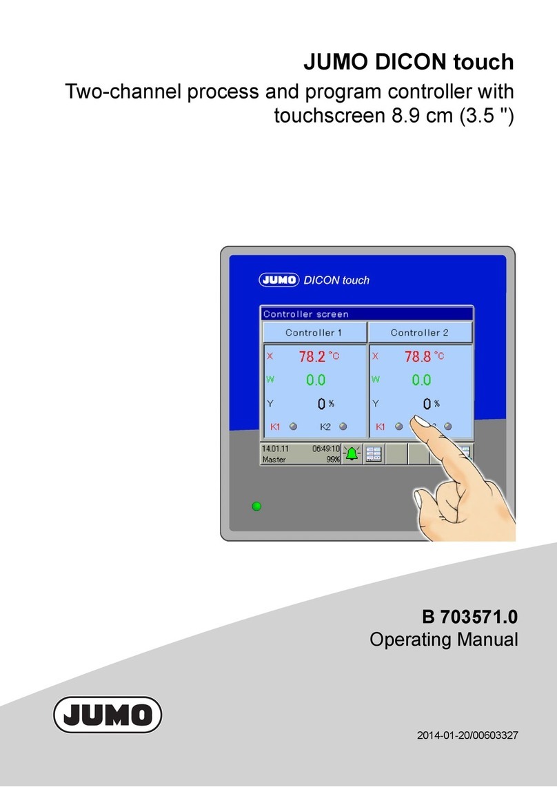
JUMO DICON touch User manual

70357107T92Z001K000
V6.00/EN/00661200/2020-01-29
JUMO DICON touch
Two-channel process and program controller with
paperless recorder and touchscreen 8.9 cm (3.5")


Contents
Contents
1 Safety information. . . . . . . . . . . . . . . . . . . . . . . . . . . . . . . . . . . . . . . . . . . . 5
1.1 Warning symbols. . . . . . . . . . . . . . . . . . . . . . . . . . . . . . . . . . . . . . . . . . . . . . . . . . . . . . . . . .5
1.2 Note signs . . . . . . . . . . . . . . . . . . . . . . . . . . . . . . . . . . . . . . . . . . . . . . . . . . . . . . . . . . . . . . .5
2 Compatibility and system requirements . . . . . . . . . . . . . . . . . . . . . . . . . . 7
2.1 Certification . . . . . . . . . . . . . . . . . . . . . . . . . . . . . . . . . . . . . . . . . . . . . . . . . . . . . . . . . . . . . .7
2.2 PROFINET IO and Ethernet standard services . . . . . . . . . . . . . . . . . . . . . . . . . . . . . . . . . .7
2.3 Requirements for hardware, software, and cabling . . . . . . . . . . . . . . . . . . . . . . . . . . . . . . .7
3 Electrical connection . . . . . . . . . . . . . . . . . . . . . . . . . . . . . . . . . . . . . . . . . 9
4 The GSDML file . . . . . . . . . . . . . . . . . . . . . . . . . . . . . . . . . . . . . . . . . . . . . . 11
4.1 General information . . . . . . . . . . . . . . . . . . . . . . . . . . . . . . . . . . . . . . . . . . . . . . . . . . . . . . .11
4.2 Module description . . . . . . . . . . . . . . . . . . . . . . . . . . . . . . . . . . . . . . . . . . . . . . . . . . . . . . . .11
4.2.1 Introduction to the module concept. . . . . . . . . . . . . . . . . . . . . . . . . . . . . . . . . . . . . . . . . . . .11
4.2.2 Modules . . . . . . . . . . . . . . . . . . . . . . . . . . . . . . . . . . . . . . . . . . . . . . . . . . . . . . . . . . . . . . . .11
5 Noncyclical data exchange . . . . . . . . . . . . . . . . . . . . . . . . . . . . . . . . . . . . 19
5.1 Programming the noncyclical data exchange in the IO controller. . . . . . . . . . . . . . . . . . . . .19
5.1.1 Single-ID and Multi-ID. . . . . . . . . . . . . . . . . . . . . . . . . . . . . . . . . . . . . . . . . . . . . . . . . . . . . .21
5.1.2 Programs for program controllers . . . . . . . . . . . . . . . . . . . . . . . . . . . . . . . . . . . . . . . . . . . . .26
5.2 Data tables of noncyclical data . . . . . . . . . . . . . . . . . . . . . . . . . . . . . . . . . . . . . . . . . . . . . . .36
5.2.1 Configuration data and parameters . . . . . . . . . . . . . . . . . . . . . . . . . . . . . . . . . . . . . . . . . . .36
5.2.2 Process values . . . . . . . . . . . . . . . . . . . . . . . . . . . . . . . . . . . . . . . . . . . . . . . . . . . . . . . . . . .42
6 Project planning . . . . . . . . . . . . . . . . . . . . . . . . . . . . . . . . . . . . . . . . . . . . . 45
6.1 Project integration of JUMO IO devices . . . . . . . . . . . . . . . . . . . . . . . . . . . . . . . . . . . . . . . .45
6.2 Configuring PROFINET modules . . . . . . . . . . . . . . . . . . . . . . . . . . . . . . . . . . . . . . . . . . . . .46
6.3 Configuring the JUMO IO device . . . . . . . . . . . . . . . . . . . . . . . . . . . . . . . . . . . . . . . . . . . . .50
6.3.1 Start-up parameters . . . . . . . . . . . . . . . . . . . . . . . . . . . . . . . . . . . . . . . . . . . . . . . . . . . . . . .50
6.3.2 Communication parameters . . . . . . . . . . . . . . . . . . . . . . . . . . . . . . . . . . . . . . . . . . . . . . . . .50
6.3.3 Device information . . . . . . . . . . . . . . . . . . . . . . . . . . . . . . . . . . . . . . . . . . . . . . . . . . . . . . . .53
7 Error messages . . . . . . . . . . . . . . . . . . . . . . . . . . . . . . . . . . . . . . . . . . . . . . 57
7.1 Error messages for invalid values. . . . . . . . . . . . . . . . . . . . . . . . . . . . . . . . . . . . . . . . . . . . .57
7.2 Error messages for acyclic services . . . . . . . . . . . . . . . . . . . . . . . . . . . . . . . . . . . . . . . . . . .57
Contents

5
1 Safety information
1 Safety informat ion
1.1 Warning symbols
DANGER!
This symbol indicates that personal injury from electrocution may occur if the appropriate precaution-
ary measures are not taken.
WARNING!
This symbol in connection with the signal word indicates that personal injury may occur if the respective
precautionary measures are not carried out.
CAUTION!
This symbol in connection with the signal word indicates that material damage or data loss will occur
if the respective precautionary measures are not taken.
CAUTION!
This symbol indicates that components could be destroyed by electrostatic discharge (ESD = Electro
Static Discharge) if the respective cautionary measures are not taken.
Only use the ESD packages intended for this purpose to return device inserts, assembly groups, or as-
sembly components.
1.2 Note signs
NOTE!
This symbol refers to important information about the product, its handling, or additional benefits.
READ THE DOCUMENTATION!
This symbol, which is attached to the device, indicates that the associated documentation for the de-
vice must be observed. This is necessary to identify the nature of the potential hazard, and to take
measures to prevent it.
REFERENCE!
This symbol refers to additional information in other sections, chapters, or other manuals.
FURTHER INFORMATION!
This symbol is used in tables and indicates that further information is provided after the table.
&
DISPOSAL!
At the end of its service life, the device and any batteries present do not belong in the trash! Please en-
sure that they are disposed of properly and in an environmentally friendly manner.

1 Safety information
6

7
2 Compatibility and system requirements
2.1 Certification
JUMO IO devices are certified by the PNO to Conformance Class B (abbreviated to CC-B) and net load
class "Netload Class III".
The certificate for the JUMO DICON touch is available for download from the product page on the Inter-
net.
The following QR code or web address will take you to the product page of the JUMO DICON touch:
qr-703571-en.jumo.info
2.2 PROFINET IO and Ethernet standard services
The PROFINET interface supports all Ethernet standard services. Over this interface, the device can
also be accessed via the JUMO PC setup program and the JUMP PCC/PCA software. Additionally, the
JUMO field device can send its e-mails over this interface. The Ethernet standard services are also avail-
able during the cyclical PROFINET communication.
The PROFINET IO communication occurs in a parameterizable time pattern (RT channel). This ensures
that the IO data are transferred in real-time without being affected by Ethernet standard services. The
remaining time between the RT phases (NRT channel) is used for the communication between the
Ethernet standard services. Broadband bottlenecks impair the performance of the standard services.
The real-time capability of the PROFINET IO communication is guaranteed by the reserved RT channel.
2.3 Requirements for hardware, software, and cabling
Network installation
Any switches used to network PROFINET IO devices must support the following standards and func-
tions:
• 100 Mbit/s (transfer rate of the switchports)
• Auto negotiation (automatic setting of the switchport transfer rate)
• Cut through (direct relaying of the data between the switchports)
Full duplex support for the switchports
IEEE 802.1 Q (VLAN support for at least 4 priority classes)
The network installation must be executed compliant with the requirements of a 100Base TX Ethernet
network with cabling to CLASS D or higher. The "PROFINET Cabling and Interconnection Technology"
guideline also provides information on correct cabling.
JUMO DICON touch
To use the PROFINET IO with JUMO DICON touch, the device must meet the following minimum re-
quirements:
• Device software version 206.03.xx or higher
• Hardware compatibility index 0x2 or higher

2 Compatibility and system requirements
8
The information can be displayed and reviewed with the aid of the device menu.
Display device software version:
Device menu > Device info > General > Version > SW version
Display hardware compatibility index:
Device menu > Device info > General > Version > HW compatibility index

9
3 Electrical connection
Cabling
JUMO field devices with PROFINET IO interface have two Ethernet switchports. Additional field devices,
IO controllers, an IO supervisor (programming device and/or PC for project planning) or other Ethernet
components such as switches, routers etc. can be connected to each Ethernet switchport on the device.
(1) PROFINET IO controller (PLC, control station PC or similar)
(2) JUMO PROFINET IO devices
(3) free Ethernet port (e.g. for additional PROFINET IO devices)
NOTE!
The cyclical data exchange with JUMO PROFINET IO devices is based on the RT protocol (Confor-
mance Class B). PROFINET RT communication cannot be routed. It is thus necessary that the PROF-
INET IO controller and the IO devices be in a common broadcast domain (not connected via a router).
Ethernet standard services (webserver, access via JUMO PC setup program/PCA/PCC and e-mail func-
tion) and NRT communication (e.g. project planning on the IO supervisor, system boot, noncyclical data,
etc.) function via routers as before.
1
2
3
4
5
6
7
8
9
10
Tx+/Rx+
Tx-/Rx-
1
2
3
4
1
2
3
1
2
3
8
18
1
N
(L-)
L1
(L+)
1
2
3
4
1
2
3
4
5
6
7
8
9
10
Tx+/Rx+
Tx-/Rx-
1
2
3
4
1
2
3
1
2
3
8
18
1
N
(L-)
L1
(L+)
1
2
3
4
(1) (3)(2)

3 Electrical connection
10

11
4 The GSDML file
4 The GSDML file
4.1 General information
The GSDML file of a PROFINET device contains all the information required to provide your PLC engi-
neering system with the PROFINET IO functionality of the JUMO DICON touch. It must be imported into
the engineering system so that the JUMO DICON touch is available here for project planning. Once the
GSDML file has been imported, the relevant device and its IO functions can be integrated into the pro-
gramming system of your PLC projects.
4.2 Module description
4.2.1 Introduction to the module concept
The configuration of the IO data of JUMO field devices to be transferred via the PROFINET IO is defined
by the PROFINET modules of the device software.
The "DeviceStatusBlock" module of JUMO field devices has a defined configuration and cannot be
changed. It contains a range of cyclical IO data on the device status and the PROFINET start-up param-
eters for the JUMO field device concerned. In the project structure of the IO controller, this module is
always located in Slot 1 of JUMO IO devices. It cannot be relocated or removed.
The JUMO PC setup program can be used to create additional modules in the module configuration of
the device concerned. This involves device data being selected from the selectors in the JUMO field de-
vice and assigned to the corresponding IO items in the modules. The PC setup program can be used to
print the finished module configuration as a basis for the project planning of the IO controller. In the proj-
ect configuration of the IO controller, the modules to be transferred via the PROFINET-IO have to be as-
signed to the free slots of the JUMO IO device in the project structure of the IO controller. The IO items
of the inserted modules are then available for the programming of the IO controller. The assignment of
the JUMO field device data to the IO items of the individual modules is provided for the programmer in
the printed module configuration list.
chapter 6 "Project planning", Page 45
4.2.2 Modules
CAUTION!
All temperature values of the JUMO IO device are transferred in the unit "°C".
Misinterpretation of measured values of a JUMO IO device in the IO controller can cause errors in the
system control.
Note the unit for the transferred temperature values!
"DeviceStatusBlock" module of the JUMO DICON touch
The "DeviceStatusBlock" module of JUMO IO devices has a defined configuration and cannot be
changed. It contains a range of cyclical IO data on the device status and the PROFINET start-up param-
eters. The IO controller is only able to read the data of this module. The tables below list the data in the
"DeviceStatusBlock" module of the JUMO DICON touch.

4 The GSDML file
12
Cyclical IO data, DeviceStatusBlock
IO item Type Bit item Bit ad-
dress
Explanation
Sub-module 1
Status bits 1 USINT Collective alarm 0 Internal signals of the JUMO DICON touch
See operating manual, chapter on digital
selector configuration
Collective alarm ac-
knowledged
1
Memory alarm 2
Pre-alarm battery 3
Battery empty 4
Logon 5
USB inserted 6
Temperature in °F 7
Status bits 2 USINT – 0 Not used
–1
–2
–3
–4
–5
–6
–7
Status bits 3 USINT Manual mode, Control-
ler 1
0 Internal signals of the JUMO DICON touch
See operating manual, chapter on digital
selector configuration
Tune controller 1 1
Manual mode, Control-
ler 2
2
Tune controller 2 3
– 4 Not used
–5
–6
–7
Status bits 4 USINT – 0
–1
–2
–3
–4
–5
–6
–7

13
4 The GSDML file
Encoder status USINT – 0 Internal signals of the JUMO DICON touch
See operating manual, chapter on digital
selector configuration
Programstopsignal 1
Basic status 2
Pre-programming 3
Manual operation mode 4
Programautosignal 5
Program end signal 6
Tolerancebandsignal 7
Dummy USINT – 0 Fill byte (no function; used to satisfy require-
ments for certain data structures)
–1
–2
–3
–4
–5
–6
–7
Operating contacts UINT Operating contact 1 0 Internal signals of the JUMO DICON touch
See operating manual, chapter on digital
selector configuration
Operating contact 2 1
Operating contact 3 2
Operating contact 4 3
Operating contact 5 4
Operating contact 6 5
Operating contact 7 6
Control contact 8 7
–8
–9
–10
–11
–12
–13
–14
–15
Cyclical IO data, DeviceStatusBlock
IO item Type Bit item Bit ad-
dress
Explanation

4 The GSDML file
14
Current program
number
UINT – – Internal signals of the JUMO DICON touch
See operating manual, chapter on integer
selector configuration
Current section num-
ber
UINT – –
Current program run-
time
UDINT – –
Current
remaining program
runtime
UDINT – –
Current section run-
time
UDINT – –
Current
remaining section
runtime
UDINT – –
Current program set-
point value 1
REAL – – Internal signals of the JUMO DICON touch
See operating manual, chapter on analog
selector configuration
Current program set-
point value 2
REAL – –
Controller 1 actual
value
REAL – – Internal signals of the JUMO DICON touch
See operating manual, chapter on analog
selector configuration
Controller 1 setpoint
value
REAL – –
Controller 1 output
level
REAL – –
Controller 2 actual
value
REAL – –
Controller 2 setpoint
value
REAL – –
Controller 2 output
level
REAL – –
Analog input 1 REAL – –
Analog input 2 REAL – –
Analog input 3 REAL – –
Analog input 4 REAL – –
Analog output 1 REAL – –
Analog output 2 REAL – –
Analog output 3 REAL – –
Analog output 4 REAL – –
Analog output 5 REAL – –
Cyclical IO data, DeviceStatusBlock
IO item Type Bit item Bit ad-
dress
Explanation

15
4 The GSDML file
Binary values UDINT Digital input IN1 0 Internal signals of the JUMO DICON touch
See operating manual, chapter on digital
selector configuration
Digital input IN2 1
Digital input IN3 2
Digital input IN4 3
Digital input IN5 4
Digital input IN6 5
Digital input IN7 6
Digital output OUT1 7
Digital output OUT2 8
Digital output OUT3 9
Digital output OUT4 10
Digital output OUT5 11
Digital output OUT6 12
Digital output OUT7 13
Digital output OUT8 14
Digital output OUT9 15
Digital output OUT10 16
Digital output OUT11 17
Digital output OUT12 18
Limit value output 1 19
Limit value output 2 20
Limit value output 3 21
Limit value output 4 22
Limit value output 5 23
Limit value output 6 24
Limit value output 7 25
Limit value output 8 26
Limit value output 9 27
Limit value output 10 28
Limit value output 11 29
Limit value output 12 30
Limit value output 13 31
Empty byte USINT – Not used
Cyclical IO data, DeviceStatusBlock
IO item Type Bit item Bit ad-
dress
Explanation

4 The GSDML file
16
Configurable modules
The configurable modules are intended exclusively for transferring cyclical IO data. The assignment of
the modules can be compiled and printed via the JUMO PC setup program of the DICON touch. The
printed list will help you maintain an overview of the configured modules of the JUMO IO device during
the project planning and programming of the IO controller (PLC, host PC or similar).
chapter 6.2 "Configuring PROFINET modules", Page 46
The JUMO DICON touch supports up to 10 slots in total (9 configurable slots + DeviceStatusBlock) in
the device and 10 slots in the IO controller project. The possible types of configurable modules are listed
in the table below.
DeviceStatusBlock start-up parameter
Parameter Type Values Explanation
Byte sequence for cycli-
cal data
Bit 0 (Big Endian)
1 (Little Endian)
Selection of byte sequence for transferred cyclical
data
The byte sequence to be set is specified by the IO
controller. Please refer to the documentation for your
IO controller
Byte sequence for non-
cyclical data
Bit 0 (Big Endian)
1 (Little Endian)
Selection of byte sequence for transferred noncycli-
cal data
The byte sequence to be set is specified by the IO
controller. Please refer to the documentation for your
IO controller
IOPS handling Bit 0 (OFF)
1 (ON)
Handling of the IOPS status via the IO device
0 (OFF): The IOPS status of the relevant IO device
slot is valid following successful system boot and no
longer depends on the validity of the input data. The
validity check of the input values must be implement-
ed in the IO controller if necessary.
1(ON): The IOPS status of the respective IO device
slot communicates to the IO controller the validity sta-
tus of the input values following successful system
boot. If the IOPS status is valid, all values of the slot
are valid. If at least 1 invalid input value occurs in the
slot concerned, the IOPS status is likewise set to in-
valid.
In case of invalid float values (REAL type), JUMO
field devices map an error code in the transferred in-
put values. As a result, the error number rather than
the input value is contained.
chapter 7.1 "Error messages for invalid values",
Page 57

17
4 The GSDML file
Module types IO items Data type Data direction
IO controller
Analog input values Analog values 1 to 16, REAL read
Digital input values Digital values 1 to 32 BOOL read
Integer input values Integers 1 to 8 DINT read
Analog output values Analog values 1 to 8 REAL write
Digital output values Digital values 1 to 3 BOOL write

4 The GSDML file
18

19
5 Noncyclical data exchange
5 Noncycl ical dat a exchange
CAUTION!
All temperature values of the JUMO IO device are transferred in the unit "°C".
Misinterpretation of measured values of a JUMO IO device in the IO controller can cause errors in the
system control.
Note the unit for the transferred temperature values!
5.1 Programming the noncyclical data exchange in the IO controller
In addition to the cyclical data exchange between IO controller and IO device in the RT channel, PROF-
INET IO also offers the option of event-controlled noncyclical data exchange. The noncyclical communi-
cation is controlled by the IO controller (similar to the master-slave principle) via write/read requests and
has to be implemented by the user. Noncyclical data are provisioned by PROFINET IO users as "Record
Data". The transfer occurs in the NRT channel.
For the programming of write/read requests, the engineering systems of the various manufacturers con-
tain libraries with relevant function blocks such as "RDREC" (Read Record) and "WRREC" (Write Re-
cord).
With JUMO PROFINET IO devices, the write/read requests do not access the "Record Data" directly.
Instead, they transfer data exchange packets between IO controller and IO device, which are further pro-
cessed in the background by the field devices. For an IO controller to be able to exchange noncyclical
data with a JUMO IO device, appropriate data structures (data blocks/data type objects) have to be cre-
ated in the IO controller for the data exchange packet concerned. These data structures provide the
memory for the outgoing and incoming data exchange packets. Data exchange packets are identified by
an index, which has to be transferred to the write/read function blocks in the form of parameters. JUMO
PROFINET IO devices have 3 indices for 3 different types of data exchange packets, which are trans-
ferred via the write/read commands. The table below lists the available indices of JUMO field devices.
Within a data exchange sequence, the IO controller transfers a data exchange packet to the IO device.
The IO device processes the data exchange packet and re-provisions it for pick-up by the IO controller
(response with data or status messages). In order to control processing by the IO device (e.g. defining
the data direction and selection of noncyclical data), the data exchange packet must be parameterized
accordingly.
With JUMO IO devices, the noncyclical services are always assigned to Slot 1. In JUMO IO devices,
Slot 1 is always pre-configured. Consequently, the noncyclical services are not dependent upon the
module configuration or project planning in the IO controller, and are available as soon as the system
has successfully booted.
Index Data exchange packet Explanation
201 Single-ID For the write and read transfer of single noncyclical data points
with a length of up to 243 bytes within a data exchange se-
quence
Length of the data exchange packet: 255 bytes
202 Multi-ID For the write and read transfer of multiple noncyclical data
points within a data exchange sequence, the single data points
are allowed to be up to 4 bytes long.
Length of the data exchange packet: 640 bytes
203 Program memory For the write and read transfer of program memories (on pro-
gram controllers) within a data exchange sequence
Length of the data exchange packet: 1024 bytes

5 Noncyclical data exchange
20
Sequence of a WRREC-RDREC cycle for transferring data exchange packets
Transfer of query parameters:
ID-SPS, DIR, ID1 to ID5, etc.
WRREC.BUSY = TRUE
Waiting time 0.5 to 2 s
RDREC.BUSY = TRUE
RDREC.DONE = TRUE
WRREC.DONE = TRUE
Validating and accepting of the
response data values
Data structure for incoming
data exchange packets
JUMO IO device
Unpacking and
processing of the
query data
from the data
exchange packet
Transfer of
response data:
Values,
program data,
etc.
IO controller IO device
WRREC.request
Transfer of the data exchange packet
with query data from the IO controller to the IO device
WRREC.response
RDREC.request
Transfer of the data exchange packet
with response data from the IO device to the IO controller
RDREC.response
Receipt of the
data exchange packet
ID-PLC comparison
incomimg outgoing
Yes
No
Other manuals for DICON touch
5
Table of contents
Other JUMO Controllers manuals

JUMO
JUMO AQUIS 500 AS User manual

JUMO
JUMO eTron M 100 User manual

JUMO
JUMO dTRON 304 User manual

JUMO
JUMO IMAGO 500 User manual

JUMO
JUMO DICON touch User manual

JUMO
JUMO DICON 401 User manual

JUMO
JUMO dTRON 16.1 B 70.3011 User manual

JUMO
JUMO exTHERM-DR User manual

JUMO
JUMO AQUIS 500 RS User manual

JUMO
JUMO DICON touch User manual

JUMO
JUMO diraTRON Series User manual

JUMO
JUMO AQUIS 500 RS User manual

JUMO
JUMO DICON touch User manual

JUMO
JUMO IMAGO 500 User manual

JUMO
JUMO diraTRON 104 User manual

JUMO
JUMO IMAGO F3000 User manual

JUMO
JUMO dTRANS CR 02 User manual

JUMO
JUMO 709062/8-01-50 User manual

JUMO
JUMO TYA 202 User manual

JUMO
JUMO IMAGO 500 User manual