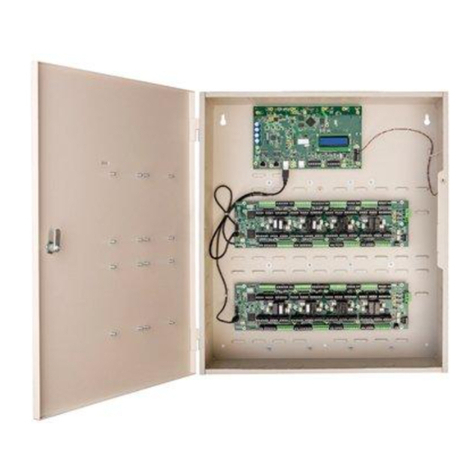
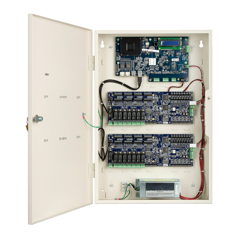
Software House iSTAR Edge User manual

1
iSTAR Edge
Quick Start Installation and
Operating Instructions
Version A4
Document Part Number UM-223
February 2010
OVERVIEW iSTAR Edge is a smaller, cost effective, two reader iSTAR that can be powered
over its Ethernet connection using Power over Ethernet (PoE), and is suitable
for placement above or near the door. iSTAR Edge can be clustered with other
iSTAR Edges and iSTAR eX’s.
Figure 1 shows a photograph of the iSTAR Edge with an optional PoE board
along with I8 and R8 modules mounted on the door.
FIGURE 1. iSTAR Edge with optional I/O Modules
I8 R8
PoE
Ethernet
Tamper
Module
(I8 and R8 not included)
(Optional)

Overview
2
iSTAR Edge Layout
FIGURE 2. iSTAR EDGE Layout
4 Inputs
AUX Power
Connector 1
RM Port 1
Relay 1
4 Inputs
AUX Power
Connector 2
Wiegand
RM Port 3
Relay 2 Relay 4
Relay 3
USB Host Ports
Power Fail Power
E-net
Tamper FAI Inputs
Low Batt
USB Device Port (Not used)
In
Output 1 Output 2
(1-4) (5-8)
RM Port 2
Wiegand

Overview
3
Main Features Main features of iSTAR Edge include:
Storage
> 250k cards.
64 MB of RAM.
128 MB of onboard flash.
Power
Powered by
Ethernet connection: PoE or PoE Plus using optional add-on board
(EdgePower) or
apS or other 12/24VDC external power source.
Provides power for:
Wiegand readers
RS-485 ports
Two 2-pin Aux 12VDC power connectors for PIRs and motion sensors.
Provides optional power to relays:
Upon loss of external power, data is written to onboard flash.
Four onboard non-rechargeable alkaline AA batteries provide power for
the backup process and maintaining the clock afterwards.
Backup is valid for > 3 days, the period the onboard batteries can
maintain the clock.
Readers
2 readers total.
2 Wiegand connectors are available.
2 RM Readers are available to be configured.
3 RS-485 serial ports are available.
Readers can be any combination of 2 from Wiegand ports and/or RMs
on any of 3 serial ports.
NOTE Onboard battery backup was tested for 3 days, but will last for weeks in
actual practice.

Overview
4
I/O
8 General Purpose Inputs.
4 General Purpose Relays:
Dry or Wet contact controlled by a jumper for each relay.
4-pin connectors to support NO/NC and Dry/Wet configurations.
4- I8 and 4- R8 allowed to be configured on any of the three RS-485 ports.
Special purpose inputs:
Tamper (from enclosure door)
Main AC fail (from apS)
Low external battery (from apS))
PoE board present
Onboard battery low
USB Ports
A USB port is used to import encryption keys, in the same way as iSTAR
eX.
Communications
One 10/100 Ethernet port.
Full 256 bit (FIPS-197) AES encryption, as with iSTAR eX
Onboard controls
LCD with backlight for diagnostics.
Rotary switch for diagnostics, as with iSTAR eX.
LEDs for serial, Ethernet, power and relay state.
Two power LEDs: one super bright LED that is on when the enclosure
door is closed, and one green LED that is always on when main power is
present.
Relay activation LEDs are not affected by enclosure door.
All other LEDs are active only when the enclosure door is open.
Reset button.
Switches for serial termination of RM ports.
Jumpers for relay Wet/Dry control.
NOTE The following two inputs to the host are determined by the firmware.
There is no actual wiring to the iSTAR Edge board.

Pre-Installation Planning
5
Housing
Optional metal enclosure (12” x 12” x 4”) with lock and tamper switch is
slightly smaller than the RM-DCM-2 enclosure.
iSTAR Edge board is mountable in existing apC/L enclosures.
Compliance
FCC, CE, EN50133, IEC60950 by CB Scheme (International Safety) & RoHS.
PRE-INSTALLATION
PLANNING
Pre-installation involves the following:
1. Checking equipment (hardware, software, power supply, and wiring).
2. Checking power, wiring, equipment clearances, and code compliance at the
site.
3. Ensuring the proper tools are available.
Equipment Check Verify that the contents of the shipped boxes match the packing lists. Contact
Software House if any items are missing or damaged.
The iSTAR Edge hardware does not include mounting hardware for an
installation. Mounting hardware depends upon the site and must be approved
by a structural engineer or other certified professional.
Software House recommends anchoring systems capable of sustaining a 20 lb.
load.
Site Check Ensure that the mounting site is ready:
Mounting dimensions
• The can is 12” by 12” (30.48 x 30.48 cm)
• Upper mounting holes are 9" (22.86 cm) center to center.
• Bottom mounting holes are 10.5" (26.67 cm) below the upper mount
holes.
The site has been approved and all wiring complies with UL requirements
and other codes, as appropriate.
All preliminary site work is complete.
An appropriate power supply is accessible.
The site is clean and free of dust or other contaminants.

Pre-Installation Planning
6
iSTAR Edge Mounting Requirements
The mounting dimensions and board overlay are shown in Figure 3.
FIGURE 3. Mounting Requirements
Voltage Requirements
and Distance
To operate properly, each reader must conform to voltage requirements.
A standard RM Series Reader or RM-4 board requires at least 7.5 volts.
An RM-4E board requires at least 11 volts.
Most Wiegand readers require a minimum of 9 volts
The iSTAR Edge supplies 12 volts at its reader connectors; however, the amount
of voltage that reaches the reader is impacted by the following:
– Number of devices on the bus
– Current draw of each device
(228.6)
9.00
(304.8)
12.00
(304.8)
12.00
DOOR 2
IN 1
IN 2
IN 3
IN 4
AUX 1
WIEGAND 1
RM 1
RELAY 1
RELAY 2
PWR
RM 3
10/100
RELAY 4RELAY 3
RM 2
WIEGAND 2
AUX 2
IN 8
IN 7
IN 6
IN 5
DOOR 1
LCD DISPLAY
OPTIONAL
POE MODULE
iSTAR
Edge
TEMPLATE
ENCLOSURE
INSTALL SHEET, iSTAR Edge,
MOUNTING TEMPLATE
8200-0910-01, REV A3
SHEET 2 OF 2, SCALE 1:1
DIMENSIONS IN INCHES
( )DIMENSIONS IN MM

Installation Requirements
7
– Wiring length between the devices and iSTAR Edge
– Wire gauge that connects the devices
– State of the battery (if running on apS)
– The tolerance if sourced by an external power supply
To determine the maximum distance of a reader from an iSTAR Edge, calculate
the voltage that reaches each reader. If the voltage is insufficient, you can
shorten the wire length, use a heavier wire, or add a UL294 local power-limited
power supply.
Wire resistance is as follows:
• 24 AWG = 26.0 Ω per 1000 ft.
• 22 AWG = 16.5 Ω per 1000 ft.
• 20 AWG = 10.2 Ω per 1000 ft.
• 18 AWG = 6.5 Ω per 1000 ft.
Installation Tools Antistatic floor mat, tabletop mat, and wrist strap.
Standard tool kit
3/32" (2.4 mm) screwdriver
Security screwdriver (contact Software House)
Small needle nose pliers; small Phillips screwdriver; wire strippers
5/16" (#10) nut driver (for securing shield wires to a ground stud)
INSTALLATION
REQUIREMENTS
This section describes iSTAR Edge hardware, software, environmental, and
configuration requirements.
Host System
Requirements
iSTAR Edge requires a host computer configured as a C•CURE 9000 system
server/host that meets all the hardware and software requirements for servers
described in the C•CURE 9000 Installation Guide.
iSTAR Edge Cabinet
Requirements
The iSTAR Edge cabinet conforms to the specifications shown in Table 1.
TABLE 1. Cabinet Assembly Specifications
Item Specification
Weight <10 lbs. (<4.6 kg)
Height 12" (30.48 cm)
Width 12" (30.48 cm)

Installation Requirements
8
Environmental
Requirements
Table 2 shows the iSTAR Edge environmental requirements.
Power Requirements The standard iSTAR Edge uses a UL Listed 603 External Power Supply, such as
the Software House apS or uses a Power Over Ethernet (PoE or PoE+) injector.
To ensure adequate power, calculate the total power requirements of iSTAR
Edge and its related hardware, as follows.
Add the total current power for components in the system (modules, relays,
optional modules, readers, and wire resistance).
Tables 3 through 6 are provided to compute the current draw of components
attached to iSTAR Edge.
iSTAR Edge Components and Boards
Table 3 shows the power requirements of iSTAR Edge components and
attached boards.
aRM-4 board has only been evaluated by UL with RM Series readers (RM 1,2,3)
bRM-4E boards have only been evaluated by UL for use with RM-DCM-2 enclosure.
Depth 4.5" (11.4 cm)
TABLE 1. Cabinet Assembly Specifications
Item Specification
TABLE 2. Environmental Requirements
Status Range
Operation 32° F (0° C) to 120° F (48.9° C)
Storage 4° F (-20° C) to 158° F (70° C)
TABLE 3. Component and Board Power Requirements
Component/Board Current Draw at 12VDC
iSTAR Edge 400 mA with LCD - no load
RM-4 boarda80 mA without LCD - no load
180 mA with LCD - no load
RM-4E boardb125 mA - no load
I/8 board 125 mA - no load
R/8 board 150 mA - no active relays.
Add 20 mA for each active relay

Installation Requirements
9
Individual/Total Loads RS-485 Reader Power Outputs: 10.6-12.5 VDC, 1.5 A max each.
Wiegand Reader Power Outputs: 10.6-12.5 VDC, 350 mA max each.
Total of all Reader and AUX outputs combined (RS-485 & Wiegand) not to
exceed 1.5 A
Four (4) activated relay coils = 100 mA (25 mA/relay)
One I/8 module – 12 VDC, total= 125 mA
One R/8 module – 12 VDC, total= 325 mA (125 ma + 25 mA for each active
relay (max 4))
R/8 relay contact ratings – 30 VDC at 1 A (resistive)
iSTAR Edge Wiegand Reader Ports
Table 4 shows the maximum ratings for iSTAR Edge Wiegand direct reader
ports.
Table 5 shows maximum rating for RM Reader ports.
Ethernet Requirements The iSTAR Edge Ethernet connection is:
Onboard 1 Ethernet port – supports 10/100Base-T Ethernet connections.
TABLE 4. Wiegand Port Rating
Port Rating
Reader output control
(red, green, yellow, beeper)
Low = 0 v to 0.8 v
High = 4.0 v to 5.25 v
20 mA maximum
Reader input data lines
(D0, D1)
Low = 0 v to 0.8 v
High = 4.0 v to 5.25 v
Reader output voltage +12 VDC
Reader current 350 mA max per reader, not to exceed
1.5 A for Readers and AUXs
TABLE 5. RM Port Rating
Port Rating
Reader output voltage +12 VDC
Reader current 1.5 A max per port, not to exceed
1.5 A for Readers and AUXs

Installation Requirements
10
Wiring Requirements Table 6 shows general wiring requirements for an iSTAR Edge and its
components.
TABLE 6. Equipment Wiring Specifications
Signal From To
Belden #
or equiv. AWG
#
Prs Shield
Max
Length
Max. Wire
Resistance
RS-485 Comm,
two wire
iSTAR
Edge
RM & I/O
Modules
9841 24 1 Yes 4000 ft.
(1212 m)
103Ω
Power iSTAR
Edge
RM & I/O
Modules
8442/8461 22/18 1 No Range of
600 ft. to
1500 ft.
depends
on AWG
See Note b
RJ45-Ethernet iSTAR
Edge
Hub, Host N/A Cat 5 or
more
24
2 N/A 328 ft.
(100 m)
8.4 Ω
Supervised
Input
iSTAR
Edge or I8
Input 8442/8461 22/18 1 No 2000 ft.
(606 m)
32Ω
Request-to-exit
(REX or RTE)
iSTAR
Edge or
RM-4/4E
module
Switch 8442/8461 22/18 1 No 2000 ft.
(606 m)
32 Ω
Door contact
(DSM)
iSTAR
Edge or
RM-4/4E
module
Contact 8442/8461 22/18 1 No 2000 ft.
(606 m)
32Ω
Supervised
Input (UL)
Note a
iSTAR
Edge or I8
Input 9462 22 1 Yes 2000 ft.
(606 m)
32Ω
Relay Control RM-4
module
ARM-1 9462 22 1 Yes 25 ft.
(7.6 m)
.04Ω
Reader Data iSTAR
Edge or
RM-4/4E
module
Proximity/
Wiegand
signaling
read head
9942
9260
Alpha wire
5386C
22
20
18
3 Yes 200 ft.
(60.96 m)
300 ft.
(91.4 m)
500 ft.
(152.4 m)
3.2 Ω (22)
3.2 Ω (20)
3.2 Ω (18)
a. To comply with UL requirements, use shielded, minimum 22 AWG stranded, twisted pair cable for monitor points,
DSMs, and REXs. Use Belden 9462 or equivalent.
b. Calculations are based on a single RM-4 reader with keypad and LCD (250 mA):
Using 22 AWG, distance = 600 ft. (.0165 Ω /ft.)
Using 18 AWG, distance = 1500 ft. (.0065 Ω /ft.)

Installation Requirements
11
Grounding
Requirements
Grounding requirements are as follows:
Ensure that the iSTAR Edge controller is properly connected to an earth
ground at the ground stud in the cabinet. (Identified by symbol.)
Use 16 AWG or larger wire.
Ensure that the shield wires for the readers, inputs, outputs, and AUX
cables are grounded to the nearest earth/ground connection at one end only
of the cable.
Disconnect the ground wire last to provide maximum protection to the
equipment and personnel.
NOTE All cabling must be shielded. See Table 6 for Belden types.
NOTE iSTAR Edge has not been evaluated by UL for operation over WAN
topologies.

Specifications
12
SPECIFICATIONS As indicated on the door map shown below, the following are power
specifications for the iSTAR Edge:
Entire Unit
• Local Power 12 VDC, 3.8 Amp Max.
• Local Power 24 VDC, 3.1 Amp Max.
Reader and I/O Module Supply (Total of AUX, RM, and Wiegand Ports)
• 12 VDC, 1.5 Amp
– AUX Ports 12 VDC 350 mA each
– RM Ports 12 VDC, 1.5 Amp each (but the max. is also 1.5 Amp for all)
– Wiegand Ports, 12 VDC, 350 mA each
Relays
• 30 VAC/DC 1.0 Amp Max. (Dry) each
• 12 or 24 VDC 0.75 Amp Max. (Wet) each
FIGURE 4. Specifications
PoE Plus
PoE
NOTE If using Power Over Ethernet (PoE), be sure that the jumper on the PoE
board is set correctly. As shown in Figure 4, there is a jumper position
for PoE and another for PoE Plus (+).

Specifications
13
Power General The iSTAR Edge can be powered by PoE, PoE Plus, or traditional 12V or 24V
DC power supplies. PoE and PoE Plus provide a method to significantly reduce
installation costs using 100 meters of ethernet cable for both power and data to
the controller.
PoE (IEEE 802.3af) installation is limited to 12.95W of power consumption
including the controller.
PoE Plus (IEEE 802.3at) installation is limited to 25.5W of power
consumption including the controller.
Careful selection of components allows a 1-door system to operate from PoE
and a 2-door system to operate from PoE Plus.
Traditional power supplies include:
An apS
Any external UPS (12/24 VDC)
Alternate Power
For those systems that exceed these limits, alternate DC supplies can be
deployed including external PoE splitters.
Alternate DC supplies are installed by the customer per the requirements of the
particular installation. When alternate DC supplies are deployed for devices on
the relay circuits, the relays circuits are configured as dry. The devices/loads do
not source power from the iSTAR Edge and are removed from the power
budget calculation.
If spare PoE/Poe Plus ports are not available in the system, PoE injectors can be
used at the source of the CAT5/6 cable.
Batteries
When onboard batteries are installed they must be fresh (they must produce
more than 5V), otherwise a too low battery-cut circuit will disconnect them. The
LCD will display information about the state of the batteries.
AC / Main Fail input:
Indicates whether the external power source has reported loss of its main
power.
Shares connector and Ground pin with Low Battery.
Normally closed dry relay contacts are required.
Configured on host as an unsupervised input, as with iSTAR eX, iSTAR Pro.
Low Battery input
Indicates whether external power source, has reported its battery is low.

Specifications
14
Wired in from external power source.
Shares connector and Ground pin with AC / Main Fail.
Normally closed dry relay contacts are required.
Configured on host as an unsupervised input, as with iSTAR eX, iSTAR Pro.
Onboard Battery Low input
Internal measurement (no connections necessary) of onboard AA alkaline
batteries.
Active if their voltage is below 4.6 volts.
Active if they are not present or one or more of them is not making full
connection.
This informs user that they should replace the onboard backup batteries for
this controller as soon as possible.
The user does not need to power down the controller to remove/replace the
batteries
Configured on host as an unsupervised input. This is a new input not
present in iSTAR eX or iSTAR Pro.
PoE Present
Internal sensing of whether PoE module is attached.
Is visible to user in the Status Tab of the iSTAR Edge Controller editor in the
C•CURE 9000 Application program. The PoE module should only be
installed or removed when board is entirely powered off.
Power in 12 / 24 VDC
iSTAR Edge can run off either 12VDC or 24 VDC power applied to the PWR
connector. Normal operating ranges include:
12V operation: 10.2 V to 14.4 V (-15/+20%)
24V operation: 20.4 to 30.0 V (-15/+25%)
Configuration for either 12V or 24V operation is stored in flash. During boot up
the iSTAR Edge detects an input power voltage as either 12 or 24 VDC and
automatically sets operation accordingly.
The iSTAR Edge will not automatically re-adjust back from 24V to 12V. This is
because a measurement of 12V input power could indicate a 12V supply or a
24V supply with a very low battery. To set the board back to 12V from 24V,
manual intervention is required:
1. Remove external power from the iSTAR Edge.
2. Select position 9on the rotary switch.

Specifications
15
3. Connect a power supply of the desired voltage (12V or 24V) to the iSTAR
Edge.
4. Watch the LCD for the message to reset the board.
5. Select position 0(or other desired position other than 9).
6. Press RESET button.
The iSTAR Edge Wiegand reader power, RS-485 serial port power and AUX
power are always configured at 12 VDC.
The Relay Wetted power is either 12 VDC or 24 VDC, depending on the input
power source.
Onboard backup
batteries
iSTAR Edge uses four onboard AA batteries to power backup to flash on loss of
main input power. These batteries must be non-rechargeable Alkaline batteries,
specifically:
AA
Alkaline
2.5 Amp hour
Button top
In order to prevent voltages that partially run the processor, the iSTAR Edge has
a battery-cut circuit. When the batteries fall below 4V, they are disconnected
from rest of the board.
The user has an onboard battery low input, configured in the host, that will
indicate when the onboard batteries need to be changed. This input will be
active when batteries are not present, not making contact, or too low to
guarantee a backup and three days of power for the clock. The user should
replace the batteries immediately when this input is active.
Backup iSTAR Edge handles backup in essentially the same way as iSTAR Classic and
iSTAR eX. When power (input voltage) drops too low to support full operation,
power usage is reduced as much as possible, processes are stopped and data is
written into flash. Processes remain stopped until the input voltage returns to a
normal operating range. At that point, iSTAR Edge reboots and reloads data
from flash to RAM and starts processing again.
The only input that controls the initiation of iSTAR Edge’s power-fail backup
process is iSTAR Edge's own onboard measurement of incoming power
voltage. iSTAR Edge measures external power voltage every 1/10 of a second.
When external power voltage moves outside of normal operating voltage (10.2
V to 14.4 V for nominal 12 V operation, or below 20.4 V for nominal 24 V
operation), iSTAR Edge will initiate the backup process.

Specifications
16
Power Out iSTAR Edge has various ways to provide power to external devices:
The following power outputs combined can provide a total of 1.5A at 12V.
• each of three serial ports
• each of two Wiegand ports
• each of two aux ports, suitable, for example, for motion sensor power.
The relays can be configured by jumper to provide power.
• Each relay is limited to 0.75A by an individual resettable fuse.
• If one load is shorted the individual fuse limits the shutdown to the
shorted load
• Power fed to wetted relay contacts is 12V for PoE or PoE plus and
otherwise is the DC input voltage.
USB provides 500mA at 5V for each device port. Each port has a resettable
fuse, this meets the USB standard and should not be exceeded by a well
functioning device.
If powered by an external DC supply the amount of power available will
depend on that supply, subject to the limits stated above.
PoE and PoE Plus have the following power limits
PoE provides 12.95W with 100 meters of cable between PSE (Power
Sourcing Equipment) and iSTAR Edge
PoE Plus provides 25.5W with 100 meters of cable between PSE and iSTAR
Edge
Cable length is part of the power budget, i.e. a shorter cable increases
available power, e.g. PoE Plus provides about 10% more power with 50
meters of cable between PSE and iSTAR Edge

Specifications
17
Door Map The Door Map shows the location of the Switches, Jumpers, and LEDs.
FIGURE 5. Door Map
Visual Indicators LCD
LCD will display diagnostic messages in a similar way to the iSTAR eX.
Diagnostics are controlled by the rotary switch, SW1.
Contrast controlled by potentiometer, RV1.
Backlight is ON when door is open, OFF when door is closed, and during
power-fail backups.
LEDs
The super-bright white Power LED is illuminated when the enclosure door is
closed, i.e. when the tamper switch closes. The power LED normally runs at
12VDC and extinguishes at about 8VDC.
The relay activation LEDs remain active regardless of the state of the enclosure
door.
The balance of the indicators are illuminated when the enclosure door is
opened. The LCD backlight and all LEDs other than the power LED and the
relay LEDs are under firmware control and are extinguished when the unit
detects input power failure and enters sleep mode to minimize power
consumption.

Specifications
18
Users have the ability, via the host, to configure LCD backlight and LEDs other
than Power LED, the Bright White external view Power LED, and the relay
activation LEDs to be always be off, regardless of tamper state.
The table below summarizes the operation of the LEDs.
TABLE 7. LED Operation
Indicator
Input
power
good,
door
closed
Input
power
good,
door
open
Input power
lost, backing
up/sleeping
Input
power
< 8V Controlled by
Power LED On On n/a Off Hardware
Bright White LED On Off Off n/a Firmware
Relay Activation LEDs On On Off Off Firmware
All other indicators, and
LCD backlight
Off On Off n/a Firmware
All other indicators, and
LCD backlight if
configured OFF in host
Off Off Off n/a Firmware

Specifications
19
The following table summarizes the function and designation of each LED
Onboard controls Reset button
The reset button performs a hard reset of the processor and as many peripherals
as possible. It causes all RAM to be erased. The Flash, including backups and
ICU configuration information, is not erased. As with iSTAR eX, use Rotary
switch position D to clear the flash and restore factory defaults.
TABLE 8. Functions of LEDs
LED Function Comment
DS21 Main Power - Internal View Always on if Voltage in > 8V
DS20 Main Power - External View Super bright White LED, visible
from outside of the enclosure
when the door is closed. Off when
the door is open.
Relay Outputs
DS15 Output 1 NO Closed Always on if Voltage in > 8V
DS14 Output 2 NO Closed Always on if Voltage in > 8V
DS13 Output 3 NO Closed Always on if Voltage in > 8V
DS8 Output 4 NO Closed Always on if Voltage in > 8V
Ethernet
DS4 Ethernet Activity Off when door is closed
DS2 Ethernet Full Duplex Off when door is closed
DS3 Ethernet 100 Mbps Off when door is closed
Serial
DS17 RS-485-1 Tx Off when door is closed
DS19 RS-485-1 Rx Off when door is closed
DS12 RS-485-2 Tx Off when door is closed
DS11 RS-485-2 Rx Off when door is closed
DS10 RS-485-3 Tx Off when door is closed
DS9 RS-485-3 Rx Off when door is closed

Specifications
20
Switches and Jumpers
Rotary switch There is an onboard 16 position rotary switch, SW1. Most of the positions are
used to control LCD diagnostics, and is similar to iSTAR eX.
Following is a reference table for iSTAR Edge rotary switch functions:
TABLE 10. iSTAR Edge Rotary Switch Functions
TABLE 9. Switches and Jumpers
Ref Type Description
SW1 Rotary Diagnostics, restore factory default and
other options.
SW7 Dual DIP Slide RS485-3 Termination
SW8 Dual DIP Slide RS485-2 Termination
SW9 Dual DIP Slide RS485-1 Termination
SW10 Push button Reset
J10 Jumper Relay Output 1 Source/Dry
J5 Jumper Relay Output 2 Source/Dry
J11 Jumper Relay Output 3 Source/Dry
J23 jumper Relay Output 4 Source/Dry
PoE Board - J2 Jumper Select PoE or PoE+
Position Description
0 ICU Block Off (Read/Write/Update) Display General Messages
1 Display card data from last card read, 7 second LCD display (slow mode)
2 Display card data from last card read, 2 second LCD display (fast mode)
3 Display supervised input changes, 2 second LCD display (slow mode)
4 Display supervised input changes, 1 second LCD display (fast mode)
5 Display manual output changes (include readers and R/8 boards), 2 second LCD display
(slow mode)
6 Display output changes (does not include readers and R/8 boards), 1 second LCD display
(fast mode)
7 Activate output test mode (include readers and R/8 boards_
8 Test Onboard Ethernet
9 Used to reset 24 V mode to 12 V mode (See Power chapter.)
A Not used
Other manuals for iSTAR Edge
1
Table of contents
Other Software House Controllers manuals
Popular Controllers manuals by other brands
EnOcean
EnOcean Omnio UPJ230/12 manual

Manning
Manning YB8 Operating and instruction manual

Magnetek
Magnetek SBN Series instruction manual
86Pixels
86Pixels PinVision for Twilight Zone installation manual
ABB
ABB PLUTO Safety-PLC operating instructions
Ametek
Ametek Magnetrol Tuffy Installation and operating manual
Bticino
Bticino AXOLUTE HD4657M3 quick start guide
Ltech
Ltech WiFi-102-CT operating instructions
Hytork Dossier
Hytork Dossier XL 45 Installation, operating and maintenance instructions
Ambient
Ambient Lockit Timecode manual
Davies Craig
Davies Craig EWP-FAN installation instructions
Danfoss
Danfoss EKA 183A installation guide
