manuals.online logo
Brands
  1. Home
  2. •
  3. Brands
  4. •
  5. iNels
  6. •
  7. Controllers
  8. •
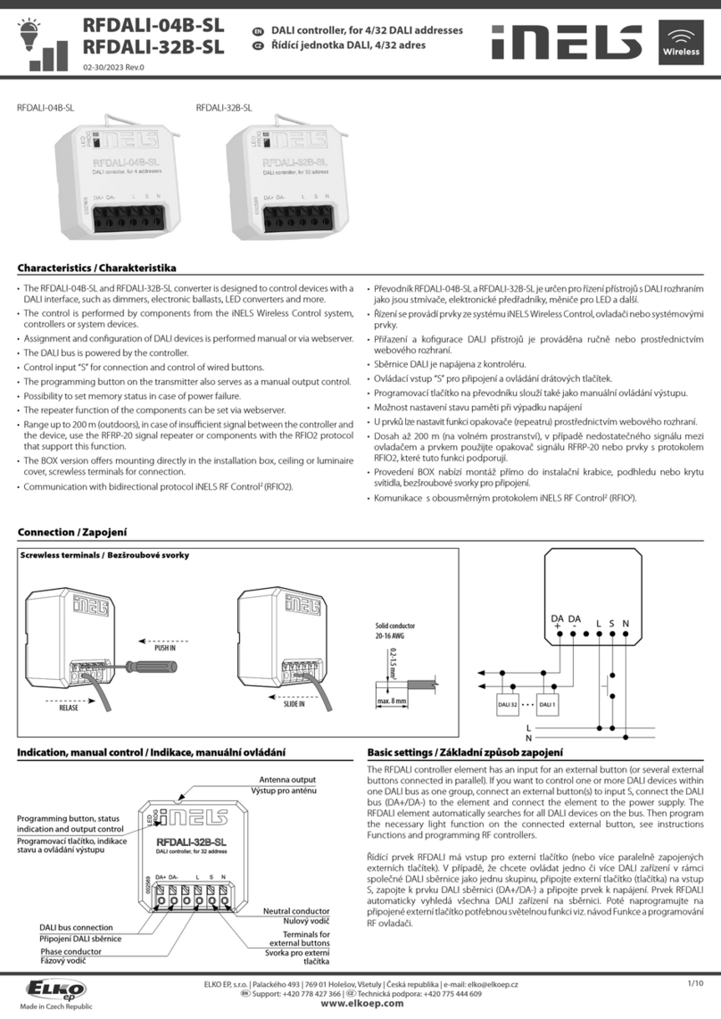
  9. iNels RFWB-20/G User manual

iNels RFWB-20/G User manual

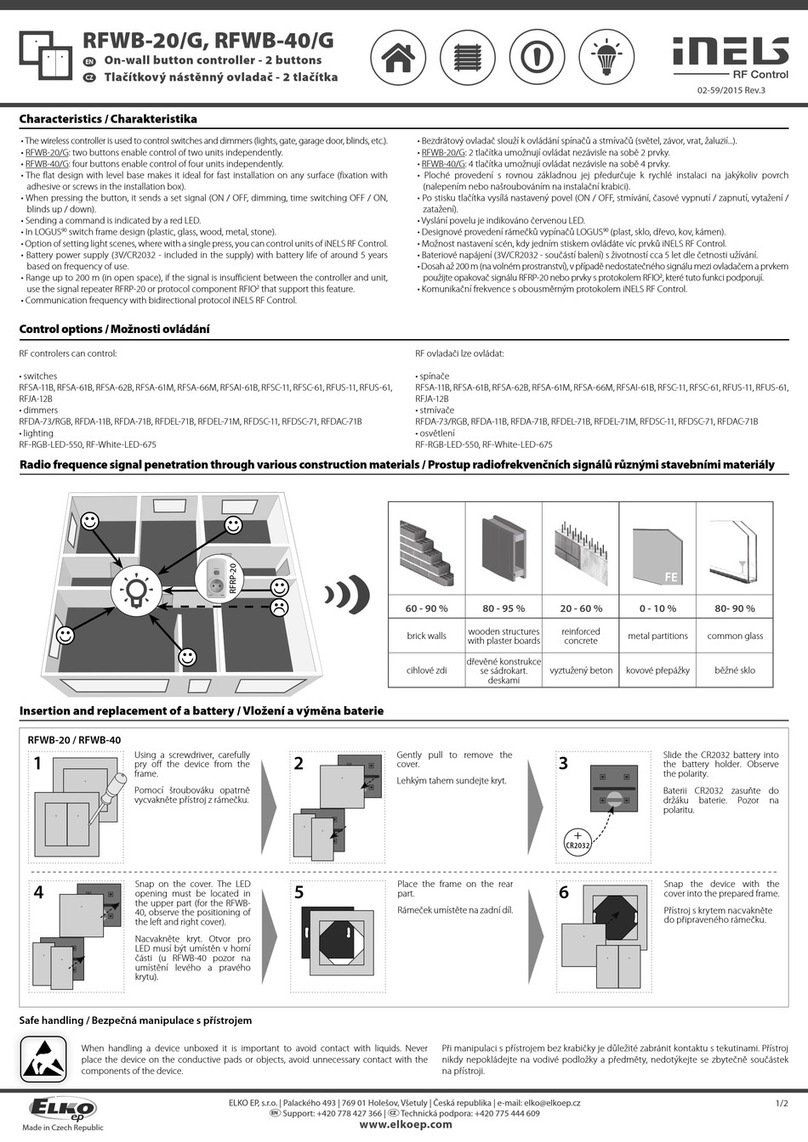
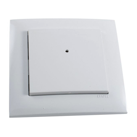
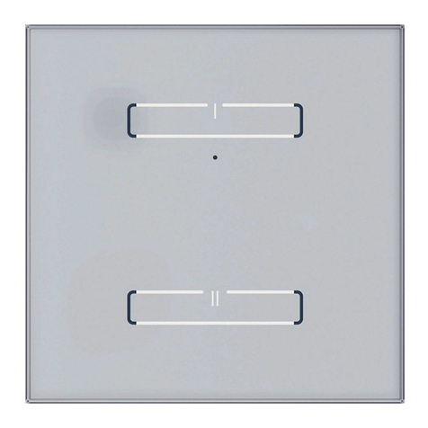
RFWB-20/G, RFWB-40/G
Wireless wall controller
EN
02-13/2019 Rev.0
1 / 2
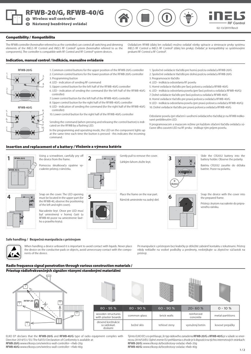
Indication, manual control /
1. Common control buttons for the upper position of the RFWB-20/G controller
2. Common control buttons for the lower position of the RFWB-20/G controller
3. Programming button
4. LED - indication of sending RF command
5. Upper control button for the left half of the RFWB-40/G controller
6. LED - indication of sending the command (for the left half of the RFWB-40/G
controller)
7. Lower control button for the left half of the RFWB-40/G controller
8. Upper control button for the right half of the RFWB-40/G controller
9. LED - indication of sending the command (for the right half of the RFWB-40/G
controller)
10. Lower control button for the right half of the RFWB-40/G controller
Sending the command (when pressing and releasing the control button) is indi-
cated on the RFWB by a flashing LED.
In the programming and operating mode, the LED on the component lights up
at the same time each time the button is pressed - this indicates the incoming
command.
1.
2.
3.
4.
RFWB-20/G
5.
7.
3.
9.
6.
8.
10.
RFWB-40/G
Compatibility /
4 5 6
3
+
CR2032
When handling a device unboxed it is important to avoid contact with liquids. Never place
the device on the conductive pads or objects, avoid unnecessary contact with the compo-
nents of the device.
Insertion and replacement of a battery /
Safe handling /
21 RFWB-20/G
RFWB-40/G
Using a screwdriver, carefully pry off
the device from the frame.
Gently pull to remove the cover. Slide the CR2032 battery into the
battery holder. Observe the polarity.
Place the frame on the rear part. Snap the device with the cover into
the prepared frame.
Snap on the cover. The LED opening
must be located in the upper part (for
the RFWB-40, observe the positioning
of the left and right cover).
The RFWB controller (hereinafter referred to as the controller) can control all switching and dimming
elements of the iNELS RF Control and iNELS RF Control2system (hereinafter referred to as the
components). The controller is compatible with RF Control and RF Control2system devices.
Radio frequence signal penetration through various construction materials /
80 - 95 % 80 - 90 % 60 - 90 % 20- 60 % 0 - 10 %
wooden structures
with plaster boards common glass brick walls reinforced
concrete metal partitions
ELKO EP declares that the RFWB-20/G and RFWB-40/G type of radio equipment complies with
Directive 2014/53 / EU. The full EU Declaration of Conformity is available at:
RFWB-20/G: www.elkoep.com/wireless-wall-controller---rfwb-20g
RFWB-40/G: www.elkoep.com/wireless-wall-controller---rfwb-40g
x
RFRP-20
Controlador pulsador inalámbrico
ES
Al manipular con el dispositivo sin embalaje es importante evitar el contacto con líquidos.
Nunca ponga el dispositivo sobre objetos conductores, no toque los componentes en el
dispositivo de forma innecesaria.
Insertar y cambiar la pila
Manipulación segura con el dispositivo
Mediante un destornillador libere con
cuidado el dispositivo del marco.
Tirando suavemente retire la tecla.
Pila CR2032 inserte al soporte de la
batería. Tenga cuidado con la polari-
dad.
Inserte de nuevo la tecla. Agujero para
LED debe ser colocado en la parte su-
perior (en RFWB-40 cuidadosamente
colocar la tecla izquierda y derecha).
Coloque el marco al elemento trasero.
Sujete el dispositivo con la tecla al
marco preparado.
Compatibilidad
El controlador RFWB (en lo sucesivo „el controlador“) puede controlar todos los dispositivos de
conmutación y atenuación del sistema iNELS RF Control ex iNELS RF Control2(en lo sucesivo, los
dispositivos). El controlador es compatible con los dispositivos del sistema RF Control y RF Control2.
Transmisión de señales de radiofrecuencia en varios materiales de la construcción
pared de ladrillo
estructuras de
madera con placas
de yeso
hormigón armado chapas metálicasvidrio normal
Por la presente, ELKO EP declara que el tipo del equipo de radio“RFWB-20/G” y “ RFWB-40/G”cumple con
la directiva 2014/53/UE. La declaración de conformidad de la UE completa está disponible en la pagina:
RFWB-20/G: www.elkoep.com/wireless-wall-controller---rfwb-20g
RFWB-40/G: www.elkoep.com/wireless-wall-controller---rfwb-40g
1. Botones de control comunes para la posición superior del controlador RFWB-20/G
2. Botones de control comunes para la posición inferior del controlador RFWB-20/G
3. Botón de programación
4. LED – indicación de enviar comando RF
5. Botón de control superior para la mitad izquierda del controlador RFWB-40/G
6. LED: indicación de envío de la órden (para la mitad izquierda del controlador
RFWB-40/G)
7. Botón de control inferior para la mitad izquierda del controlador RFWB-40/G
8. Botón de control superior para la mitad derecha del controlador RFWB-40/G
9. LED: indicación de envío de la órden (para la mitad derecha del controlador
RFWB-40/G)
10. Botón de control inferior para la mitad derecha del controlador RFWB-40/G
El envío de la órden (al presionar y soltar el botón de control) se indica en la RFWB
mediante un LED parpadeante.
En el modo de programar y borrar, con cada pulsación del botón, el LED del dispo-
sitivo RF se ilumina de forma larga, lo que indica que recibe una órden.
Indicación, control manual
Made in Czech Republic
Programming /
Snap the device with the cover into
the prepared frame.
2 3
PROG > 1s
1 x
4


5
PROG < 1s
1 x
1RFWB-20/G
RFWB-40/G
6 7 8
xxxxxx
Assignment of system components /
address / The address on the back of the controller is used for assignment to the system
components.
Press of programming button on ac-
tuator for 1 second will activate actua-
tor RF into programming mode. LED
is flashing in 1s interval.
Gently pull to remove the cover.Using a screwdriver, carefully pry off
the device from the frame.
Press of programming button on
actuator shorter then 1 second will
finish programming mode.
Snap on the cover. The LED opening
must be located in the upper part (for
the RFWB-40, observe the positioning
of the left and right cover).
Hold the programming button on the RFWB. Press the selected control button on the RFWB according
to the desired function (for more information on individual functions and programming, see the manual
of the specific component). There must be a lapse of 1 second between individual presses. Then release
the programming button.
Place the frame on the rear part.
RFWB-20/G RFWB-40/G
Supply voltage:
Transmission indication:
Number of control buttons:
Programming button:
Transmitter frequency:
Signal transmission method:
Range in free space:
Other data
Operating temperature:
Operating position:
Mounting:
Protection:
Contamination degree:
Dimensions:
LOGUS90 frame - plastic:
LOGUS90 frame
- metal, glass, wood, granite:
Weight:
Related standards:
Technical parameters /
* Comes with plastic frame, without battery.
Attention:
No installation into multi-frames.
When you instal iNELS RF Control system, you have to keep
minimal distance 1 cm between each units.
Between the individual commands must be an interval of
at least 1s.
Instruction manual is designated for mounting and also for user of the device. It is
always a part of its packing. Installation and connection can be carried out only by a
person with adequate professional qualification upon understanding this instruction
manual and functions of the device, and while observing all valid regulations. Trouble-
free function of the device also depends on transportation, storing and handling. In
case you notice any sign of damage, deformation, malfunction or missing part, do
not install this device and return it to its seller. It is necessary to treat this product and
its parts as electronic waste after its lifetime is terminated. Before starting installa-
tion, make sure that all wires, connected parts or terminals are de-energized. While
mounting and servicing observe safety regulations, norms, directives and professional,
and export regulations for working with electrical devices. Do not touch parts of the
device that are energized – life threat. Due to transmissivity of RF signal, observe cor-
rect location of RF components in a building where the installation is taking place.
RF Control is designated only for mounting in interiors. Devices are not designated
for installation into exteriors and humid spaces. The must not be installed into metal
switchboards and into plastic switchboards with metal door – transmissivity of RF
signal is then impossible. RF Control is not recommended for pulleys etc. – radiofre-
quency signal can be shielded by an obstruction, interfered, battery of the transceiver
can get flat etc. and thus disable remote control.
The company ELKO EP, as the manufacturer, is entitled to make technical modificati-
ons to the product, in the technical specification and product manual, without prior
notification.
Warning /
ELKO EP, s.r.o. | Palackého 493 | 769 01 Holešov, Všetuly | Czech Republic | e-mail: [email protected] | Support: +420 778 427 366
ELKO EP ESPAÑA, S.L. | C/ Josep Martinez 15a, bj | 07007 Palma de Mallorca | e-mail: [email protected] | Tel.: +34 971 751 425 | Fax: +34 971 428 076
www.elkoep.com / www.elkoep.es
Tensión de alimentación:
Indicación de transmisión:
Número de botones de control:
Botón de control:
Frecuencia:
Modo de transmisión de señal:
Rango aire libre:
Más información
Temperatura de funcionamiento:
Posición de funcionamiento:
Montaje:
Protección:
Grado de contaminación:
Dimensiones:
LOGUS90 Marco - plástico:
LOGUS90 Marco - vidrio,
madera, metal, granito:
Peso:
Normas conexas:
3 Vbattery / pila CR 2032
red / rojo LED
2 4
1
866 MHz, 868 MHz, 916 MHz
unidirectionally addressed message / mensaje dirigida unidireccionalmente
up to / hasta 200 m
-10 ... +50 °C
any / cualquiera
glue, screws / pegado, atornillado
IP20
2
85 x 85 x 16 mm
94 x 94 x 16 mm
55 g* 55 g*
EN 60669, EN 300220, EN 301489 R&TTE Directive, Order. No 426/2000 Coll. (Direc-
tive 1999/EC) / EN 60669, EN 300 220, EN 301 489 directiva RTTE, NVč.426/2000Sb
(directiva 1999/ES)
Especificaciones técnicas
* Con marco éstandar suministrado, sin bateria.
Advertencia:
No instale en múltiples marcos.
En la instalación de iNELS RF Control debe haber una
distancia mínima entre las diferentes unidades de un
centímetro.
Entre los diferentes ordenes debe pasar al menos 1s.
El manual de uso está dirigido para la instalación y el usuario del dispositivo.
Manual siempre está incluido en embalaje. La instalación y conexión puede realizar
sólo personal con adecuadas cualificaciones profesionales, de conformidad con
todas las regulaciones aplicadas, y que está perfectamente familiarizado con estas
instrucciones y funciones del dispositivo. Función del dispositivo también depende
del transporte, almacenamiento y la manipulación. Si se observa cualquier signo de
daño, deformación, mal funcionamiento o pieza que falta, no instale este producto y
devolvelo al vendedor. Con el producto y sus componentes debe ser tratado después
de su vida útil como con residuos electrónicos. Antes de iniciar la instalación, asegúrese
de que todos los cables, partes o terminales conectados están sin la conexión a la red.
En el montaje y el mantenimiento se deben observar las normas de seguridad, normas,
directivas y reglamentos para trabajar con equipos eléctricos. No toque las partes del
dispositivo que están conectadas en la red - puede producir peligro de vida. Debido
a la transmisibilidad de la señal RF, observe la correcta ubicación de los componentes
RF en un edificio donde la instalación se lleva a cabo. RF Control está diseñado
para montaje en interiores, las unidades no están diseñados para la instalación en
exteriores y espacios húmedos, no se pueden instalar en cuadros eléctricos de metal
y en cuadros eléctricos plásticos con puerta de metal - lo que empeora transmisividad
de la señal RF. RF Control no se recomienda para el control de dispositivos que ofrecen
funciones vitales o para controlar dispositivos tales como bombas, el. calentadores
sin termostato, ascensores, montacargas, etc. - Señal de radiofrecuencia puede estar
bloqueado por una obstrucción, interferida, la batería del controlador puede estar ya
sin energía, etc. y por lo tanto el control remoto puede ser incapacitado.
La empresa ELKO EP como fabricante tiene derecho de hacer cambios técnicos en
dispositivo, en especificaciones técnicas y en manual del dispositivo sin aviso previo.
AdvertenciaAsignación a un dispositivo del sistema
Para asignación a un dispositivo del sistema sírve la dirección que se muestra en
la parte trasera del controlador.
dirección
Mantenga presionado el botón de programación en el RFWB. Presione el botón de control seleccionado
en el RFWB de acuerdo con la función deseada (para obtener más información sobre las funciones indivi-
duales y la programación, consulte el manual del dispositivo específico). Entre cada pulsación debe haber
un retraso de 1 segundo. Luego suelte el botón de programación.
Mediante un destornillador libere con
cuidado el dispositivo del marco.
Tirando suavemente retire la tecla.
Inserte de nuevo la tecla. Agujero para
LED debe ser colocado en la parte su-
perior (en RFWB-40 cuidadosamente
colocar la tecla izquierda y derecha).
Coloque el marco al elemento trasero.
Sujete el dispositivo con la tecla al
marco preparado.
Con pulsación del botón de progra-
mación en el dispositivo RF durante
más de 1 segundo, el dispositivo se
pone al modo de programación. El
LED comienza a parpadear a interva-
los de 1 segundo.
Pulsando el botón de programación
de la unidad RF durante menos de 1
segundo, terminará el modo de pro-
gramación.
Programación
This manual suits for next models

1

Other iNels Controllers manuals

iNels GSB3-40 User manual

iNels

iNels GSB3-40 User manual

iNels SA3-06M User manual

iNels

iNels SA3-06M User manual

iNels RFWB-20/G User manual

iNels

iNels RFWB-20/G User manual

iNels JA3-018M User manual

iNels

iNels JA3-018M User manual

iNels SA3-012M User manual

iNels

iNels SA3-012M User manual

iNels RFWB-20/G User manual

iNels

iNels RFWB-20/G User manual

iNels IART2-1 User manual

iNels

iNels IART2-1 User manual

iNels RFDA-73M/RGB User manual

iNels

iNels RFDA-73M/RGB User manual

iNels RFDALI-04B-SL User manual

iNels

iNels RFDALI-04B-SL User manual

iNels WTC2-21 Simple manual

iNels

iNels WTC2-21 Simple manual

iNels RFWB-20/G User manual

iNels

iNels RFWB-20/G User manual

iNels RFWB-20/G User manual

iNels

iNels RFWB-20/G User manual

iNels JA3-014M User manual

iNels

iNels JA3-014M User manual

iNels RFWB-20/G User manual

iNels

iNels RFWB-20/G User manual

iNels SA3-02M User manual

iNels

iNels SA3-02M User manual

iNels RF KEY User manual

iNels

iNels RF KEY User manual

iNels RFDEL-76M User manual

iNels

iNels RFDEL-76M User manual

iNels SA3-01B User manual

iNels

iNels SA3-01B User manual

iNels RFWB-20/G User manual

iNels

iNels RFWB-20/G User manual

iNels RFGB-40 User manual

iNels

iNels RFGB-40 User manual

iNels JA2-02B User manual

iNels

iNels JA2-02B User manual

iNels RF KEY - 40 User manual

iNels

iNels RF KEY - 40 User manual

iNels SA2-02B Simple manual

iNels

iNels SA2-02B Simple manual

iNels RFWB-20/G User manual

iNels

iNels RFWB-20/G User manual

Popular Controllers manuals by other brands

MSA 10033170 manual

MSA

MSA 10033170 manual

Hornberg Research hb1 user guide

Hornberg Research

Hornberg Research hb1 user guide

curt ECHO 51180 installation manual

curt

curt ECHO 51180 installation manual

SOMFY J4 RTS Installer's guide

SOMFY

SOMFY J4 RTS Installer's guide

Rittal RiLine SV 9635.400 Assembly and operating instructions

Rittal

Rittal RiLine SV 9635.400 Assembly and operating instructions

Hoval TopTronic E instructions

Hoval

Hoval TopTronic E instructions

Chiyu Technology BF-2300 user guide

Chiyu Technology

Chiyu Technology BF-2300 user guide

TIE DOWN 750E Installation, instruction and  service manual

TIE DOWN

TIE DOWN 750E Installation, instruction and service manual

Morningstar TriStar Professional TS-60M Installation, operation and maintenance manual

Morningstar

Morningstar TriStar Professional TS-60M Installation, operation and maintenance manual

Engineered air EngA M-TRAC1 User's operation manual

Engineered air

Engineered air EngA M-TRAC1 User's operation manual

Siemens SINUMERIK 840D sl Programming manual

Siemens

Siemens SINUMERIK 840D sl Programming manual

Robotics RT-1000 quick start guide

Robotics

Robotics RT-1000 quick start guide

ABB PSE18 Replacing Guide

ABB

ABB PSE18 Replacing Guide

IAI MCON-C instruction manual

IAI

IAI MCON-C instruction manual

Tescom 44-3400 Series Instructions for use

Tescom

Tescom 44-3400 Series Instructions for use

Watlow PC1X-N20 user manual

Watlow

Watlow PC1X-N20 user manual

Bard LV1000-100 INSTALLATION SUPPORT MATERIALS

Bard

Bard LV1000-100 INSTALLATION SUPPORT MATERIALS

GE 90-30 PLC Installation and Hardware Manual

GE

GE 90-30 PLC Installation and Hardware Manual

manuals.online logo
manuals.online logoBrands
  • About & Mission
  • Contact us
  • Privacy Policy
  • Terms and Conditions

Copyright 2025 Manuals.Online. All Rights Reserved.