Software House iSTAR Ultra SE Manual

1
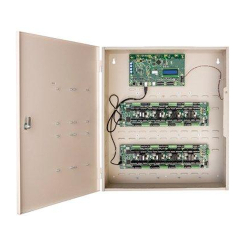
iSTAR Ultra SE Controller
Hardware Installation
Version D0
Part Number UM-311
October 2017
OVERVIEW
The iSTAR Ultra SE can be configured as an iSTAR Pro (in Pro Mode) or as an
iSTAR Ultra (in Ultra Mode for use with C•CURE 9000). The configuration is
based upon the GCM S1-4 switch setting.
The iSTAR Ultra consists of the following hardware components:
General Controller Module (GCM)
Access Control Module (ACM) - 2 maximum
or IP-ACM Ethernet Door Modules (supported in Ultra Mode only) - 32
maximum (IP-ACM installation and configuration is not included in this
document, see the IP-ACM Ethernet Door Module Quick Start Guide)
General Control
Module
The GCM is a General Purpose Module running the Linux®operating system.
The GCM provides the following features:
Two network Gigabit Ethernet ports.
An LCD panel that displays the current status, and provides built-in
diagnostics.
NOTE The iSTAR Ultra SE in Pro Mode is supported by C•CURE 9000 and C•CURE 800/8000. Refer to
the iSTAR Pro Controller software configuration information when using the C•CURE 9000 or the
C•CURE 800/8000.
Pro Mode does not support the optional RC4 network encryption setting in either C•CURE 800 or
C•CURE 9000 systems. Check the Message Encryption system variable to ensure RC4 is not being
used.
The iSTAR Ultra SE in Ultra Mode is only supported on C•CURE 9000 v2.50 and higher. Refer
to the iSTAR Ultra Controller software configuration information when using the C•CURE 9000.
The iSTAR Ultra SE in Ultra Mode has a reduced feature set when compared to the iSTAR Ultra.
There are 16 Inputs instead of 24 and 8 Relays instead of 16, per ACM and no embedded lock
power management.

Overview
2
Two RS-485 Ports for Aperio™hubs and wireless locks, or Schlage®PIMs
and wireless locks.
Up to 30 eight-port Aperio hubs (15 per RS485 port) up to 32 Aperio
locks.
Or,
Up to 32 16-port Schlage PIMs (16 per RS485 port) up to 32 Schlage
locks.
Tamper switch for security.
Four USB ports to communicate with the ACM and import encryption keys.
(USB Ports have only evaluated by UL for connection to ACMs)
External Power Fail and Battery Monitoring Inputs.
Access Control
Module
The ACM is a special purpose Access Control Module that interfaces with the
GCM and provides inputs, outputs, and reader interfaces. An iSTAR Ultra SE
can contain up to two ACMs that interface directly with Wiegand signaling
devices and RM reader busses. The RM reader busses can interface with
Wiegand signaling devices and ABA (magnetic) signaling devices. FAI (Fire
Alarm Interface) is also supported along with the ability to selectively energize
the relays and optionally latch them until released by a Key switch. The
maximum number of readers per ACM is 8.
IP-ACM Ethernet Door
Module
The IP-ACM module provides connection and management of the access
control for two readers. The GCM supports a maximum of 32 IP-ACM modules
with 1 reader per IP-ACM or a maximum 16 IP-ACMs with 2 readers per IP-
ACM. The limiting factor is a maximum of 32 readers.
For the iSTAR Ultra SE to operate with the IP-ACM v1 modules, the GCM
must be running firmware version 6.4.1 or higher and C•CURE 9000 must be
version 2.50 SP1 or higher.
For the iSTAR Ultra SE to operate with the IP-ACM v2 modules, the GCM
must be running firmware version 6.5.4 or higher and C•CURE 9000 must be
version 2.60 or higher.
For more information regarding the features and installation of the IP-ACM,
refer to the IP-ACM Ethernet Door Module Quick Start Guide.
NOTE Aperio hubs and readers have not been evaluated by UL.
NOTE Only two ACMs are supported.
NOTE FAI/Key inputs are not supported on the iSTAR Ultra SE in Pro Mode.

Requirements
3
Types of Mounting The iSTAR Ultra SE, and its components, can be installed in a wall mount
enclosure or in a separate rack mount enclosure.
REQUIREMENTS
Site Requirements Ensure that the site is ready:
The iSTAR Ultra SE installation must be performed by a certified installer.
All Control Units of the iSTAR Ultra SE must be installed in a restricted
access protected area.
Non-limited power supply lines, lines capable of sourcing 5A or more, must
maintain (1/2 inch (1.3 cm)) spacing from limited power supply lines and
other signaling lines. Secure lines must be installed in accordance to local
and national electric codes.
The site must be approved and all wiring must comply with UL requirements
and other codes, as appropriate. Installation shall be in accordance with the
National Electric Code, ANSI/NFPA 70-1993.
Wall Mount Dimensions Table 1 on page 3 lists the iSTAR Ultra SE Cabinet Wall Mount Dimensions
Environmental
Requirements
Table 2 on page 3 lists the iSTAR Ultra SE environmental requirements.
Table 1. Cabinet (Wall Mount Dimensions)
Item Dimension/Location
Weight 26.5 lb (12.02 kg)
Height 24.25 in. (61.6 cm)
Width 16.5 in. (41.9 cm)
Depth 4 in. (10.3 cm)
Upper Mounting
Holes
There are 2 upper keyhole type mounting holes that are spaced 14.25 in.
(36.2 cm) from each other. These two mounting holes are 7.125 in. (18.1
cm) from the enclosure center line.
Two Bottom
Mounting Holes
Directly below the upper mounting holes.
Table 2. Environmental Requirements
Status Range
Operation 32°F (0°C) to 120°F (49°C)
Storage 4° F (-20°C) to 158°F (70°C)
Altitude 6600 ft. (2000 m) maximum
Humidity 0 to 85%RH (Non-condensing)

Installation
4
INSTALLATION
This section assumes that the site meets the requirements.
Wall Mount Installation The most common installation is the wall mount. In this installation, the
enclosure is mounted directly to a wall or uni-strut using suitable user-supplied
hardware.
Requirements
The anchoring system must be capable of sustaining 75 lb (34 kg). This
weight does not include the cables.
The cables are protected by use of conduit, which is metal, plastic, or flexible
cable grip strain relief.
An external power supply provides 12 Vdc to power the iSTAR Ultra SE.
If an ACM is powered by a different Power Supply Unit (PSU), the ACM Fail
trigger must be configured to alarm on failure.
For a UL installation the Power must be approved to UL-294 and/or UL-603.
To Wall Mount the Controller:
1. Carefully unpack the components. Software House recommends removing
the GCM and the ACM(s) from the enclosure before mounting. Use ESD
procedures while handling the boards.
2. Open the enclosure door and disconnect the grounding wire on the door.
3. Carefully lift the door off the hinges and place it on a padded surface.
4. Verify that the upper mounting screws (or equivalent) are in place on the
mounting site for the keyhole locations.
ELECTROSTATIC SENSITIVE DEVICES: Observe precautions for handling.
Before handling any internal components, discharge static electricity by holding a
grounding lug or non-painted grounded surface for three seconds.
Wear a grounding wrist strap and stand on a grounded static mat.
Reduce movement during installation to reduce static buildup.
Make sure work area is safeguarded.
Transport components in static-shielded containers.
Note: The outside of the ESD bags are not ESD protective.
Verify that all components, materials, and the installer are referenced to a common
ground.
NOTE See Figure 1 on page 5 for the location of the keyhole slots, screws, and knockouts.

Installation
5
Figure 1. iSTAR Ultra SE Controller with Door Removed (Two ACMs Mounted)
LCD
5. Align the mounting keyhole slots at the upper back of the enclosure with the
two upper mounting screws, and lower the enclosure into position.
6. After the enclosure is mounted tighten the mounting screws.
7. Install the two lower mounting screws.
8. Attach the conduit couplings to the knockout openings as needed to comply
with local code requirements.
9. Reattach the grounding wire between the door and the enclosure.
10.Connect to a grounding lug with a low impedance cable going to Earth
Ground.
11. When routing signal cables from the ACM to accessory boards on the door,
ensure that the cables are not pinched by the door and cables are routed in
accordance with NEC Codes or the applicable Local codes.
Ground Stud
(6-32)
For Shield Wire,
1 By Each Knockout
Assorted Knockouts
Cabinet/Enclosure
General Controller
Module (GCM)
Access
Control
Module
(ACM)
Assorted
Knockouts
Keyhole
Mounting
Slot (2)
Lower Mounting
Hole (2)
Tamper Switch
Assorted
Knockouts
USB Cables
ACM 1
ACM 2
GCM
E-Net
Tamper
LCD
LCD
Reader & Logic Power
Reader & Logic Power

Installation
6
12.Use the appropriate conduit or strain relief with proper spacing according to
local and national codes. Building power shall be routed and connection will
be made at the terminal block inside the enclosure.
Wall Mount Door Components
The wall mounted iSTAR Ultra SE has stand-off’s on the enclosure door that
can support up to two RM Bus components.
The I/8, I/8-CSI, R/8, and RM-4E boards are supported. There can be any
combination of these boards.
Board Configuration Examples:
Two I/8’s, two I/8-CSI’s, two R/8’s or two RM-4E’s
One I/8 and one R/8, etc.
Wiring: Route the RM bus from each RM device to the next. Connect the end to
one of the RM connectors on the ACM (for example, STAR1 through STAR8).
See Figure 2 on page 6. Terminate the last unit but not the middle unit.
Figure 2. Wiring Wall Mount Door Components
NOTE During configuration, be sure to note the values of the pins on the boards for correct wiring.
Pin 1
Use Care not to pinch
wiring at this location

Installation
7
Rack Mount Installation The GCM and ACMs are mounted separately in standard 19-inch racks. The
cables will be inside the cable management system of the rack. The
components must remain secure, be clearly labeled, and be easily accessible
when using the correct tools.
Rack Mount Considerations
Be aware of the following considerations when mounting the iSTAR Ultra SE as
a Rack Mount:
Rack Mount ACM's need to located close enough so that the 3 foot USB
supplied cable can be routed and still have a proper service loop.
Elevated Operating Ambient - If installed in a closed or multi-unit rack
assembly, the operating ambient temperature of the rack environment may
be greater than room ambient. Verify that 0to 49is maintained.
Reduced Air Flow - Installation of the equipment in a rack should be
such that the amount of air flow required for safe operation of the
equipment is not compromised. Verify that 0to 49is maintained.
Reliable Grounding - Reliable earth ground of rack-mounted equipment
should be maintained.Grounding needs to follow NEC Codes or the
applicable Local code.
To Perform a Rack Mount Installation:
1. Pick a location for the rack, while observing the “Rack Mount
Considerations” on page 7.
2. Mount the unit with either 10/32 or 12/24 hardware.
3. Connect Ethernet, as required, to the Ethernet port(s).
4. Secure the power inputs with zip-ties to maintain minimum safe distance for
electrical safety. Install in accordance with local and national regulations.
Grounding
Requirements
Grounding requirements are as follows:
Grounding needs to follow NEC Codes or the applicable Local code.
Ensure that the iSTAR Ultra SE controller is properly connected to an earth
ground at the ground studs.
Shielded wires should have the shields grounded to the chassis enclosure
as close as possible where the respective cables are entering the enclosure.
NOTE Use a service loop when connecting the cables.
NOTE If you are mounting the iSTAR Ultra SE in Pro Mode as a rack mount, the ACM must be
tampered with a supervised input dedicated as a tamper.
NOTE The iSTAR Ultra SE must be installed in a UL-listed rack mount for UL compliant installations.

Power
8
When disconnecting wiring, disconnect ground wires last (to provide
maximum protection to the equipment and personnel).
POWER
This section provides the power requirements for the iSTAR Ultra SE and its
components. A limited power supply (LPS class 2) is required.
Electrical Electrical ratings are dependent upon the configuration.
GCM
Power Input (12 Vdc -15%, +10%)
• 12 Vdc , 1.5A minimum, 4.5A maximum (if fully loaded)
Power Output
• RS485:12 Vdc , nominal, 1.3A maximum each port.
ACM
Power Input (12 Vdc -15%, +10%)
Power Output
• RS485: 12 Vdc nominal, (11.14V measured) from external power
supply
▫1.3A maximum per port
▫11 Vdc with STAR-PS
• Wiegand: 12 Vdc nominal (11.4V measured) from external power
supply, (11.3V measured with STAR-PS)
▫800mA maximum per output, total not to exceed 5A
▫4.7 Vdc from an external power supply
▫0.8A maximum per output, total not to exceed 1.25A
▫5Vdc is 800mA maximum per output, total not to exceed 1.25A
• Dry Relay Out: 30 Vdc/Vac, 5A maximum each
• Total output from the STAR-PS not to exceed 5A
Disconnect all sourced power before modifying the wiring.
NOTE GCM RS485 outputs were evaluated by UL only for connection to Schlage PIM-400/AD-400
Readers and Locks.
NOTE The Wiegand, RS-485, and Aux ports are power limited on the ACM.

Power
9
IP-ACM (supported in Ultra Mode)
Power Input
• 12 or 24 Vdc 32W maximum
• IEEE 802.3af (PoE) and 802at (PoE Plus), 25.5W maximum. LLDP
supported for PoE Plus
UL tested with PHIHONG PoE injector model POE36U-1AT-R
Power Output
RS485/Wiegand: 12 Vdc; The aggregate load of each pair of RS-485 and
Wiegand connections together must not exceed 750mA. Each set of
RS-485 and Wiegand can support 750mA. Maximum combined output
limit for readers and locks is 17W.
Wet Relay: 12 or 24 Vdc (jumper selectable)
– 0.5A (per lock) IP-ACM v1 (P/N 0312-7166-01)
– 0.75 (per lock) IP-ACM v2 (P/N 0312-7239-01)
Dry Relay: 0 to 30 Vdc, 5A maximum. NO, 3A maximum. NC
AC Power
100-240 VAC~1.7A, 50-60Hz
The iSTAR Ultra SE comes with the power supply installed. There is an optional
powers supply that can be purchased (STAR-PS or USTAR-PS) for Access
Control only, not standby-power.
Additional Power
Requirements
An external over-current protection device (i.e. circuit breaker) must be
installed in a secure location readily accessible to a service person.
Circuit Breakers need to be sized so that its normal sourced current does not
exceed 80% of the circuit breaker rating.
The system power circuit breaker must only be assessable by Authorized
Personal.
NOTE Compliance with IEEE 802.3 (AT or AF) specifications was not verified as
part of UL294/B.
NOTE USTAR-PS has not been evaluated by UL.
RISK OF ELECTRICAL SHOCK:
Installation and maintenance must only be performed by qualified persons.
Disconnect from branch-circuit supply before installation.
Ensure that the iSTAR Ultra SE enclosure (STAR-CAN, P/N 0505-2020-01) is properly
connected to an earth ground at the ground stud near the AC input wiring.

Power
10
Battery The GCM contains a rechargeable 3V CR2032 lithium coin cell battery that is
used to retain the real-time clock for at least three weeks. After three weeks of
accumulated power outage, the battery should be replaced.
Detaching the Pull-Tab from the Battery Holder
You need to detach the pull-tab from the battery holder before you put the board
online. After the tab is pulled out, and the board is configured, the battery can
only maintain the Real Time Clock (RTC) for 30 days without power supplied to
the board.
The iSTAR Ultra SE must be supplied by a 15A circuit breaker protected branch-circuit.
FOR BURGLAR ALARM INSTALLATIONS:
The iSTAR Ultra SE is not provided with backup power. An external power supply
must be provided with the following characteristics:
UL 603 and/or UL 294 Listed
Minimum four hours of standby power.
The iSTAR Ultra SE is not UL1076 approved when used with internal STAR-PS.
Tyco / Software House Advanced Power Supply (apS) used in-conjunction with the
iSTAR Ultra SE will be sufficient in meeting the requirements of UL-1076.
When using external power supply, the supply shall be Class 2, and compliant with EN/
IEC 60950-1 or IEC 62368.
All Burglar Alarm and Intrusion Zone inputs must be supervised and have Triggers
configured to Alarm upon Tamper.
At least one RM2L Series reader must be in each area/partition for signal
acknowledgement.
There are multiple power inputs to the unit. To completely de-energize the unit,
disconnect ALL power sources.
NOTE For UL Listed products, a UL 603 and UL 294 listed power supply must be used.
NOTE In the absence of power failures, the expected coin cell battery life is five years.
The replacement battery must be UL approved.
The battery on the GCM shall be checked and replaced only by a trained
technician.

Power
11
Wiring Requirements The iSTAR Ultra SE Ethernet connections are two GCM Inboard Ethernet ports
which support up to 1 Gbps each (auto-sense 10, 100, 1000 Mbps).
Table 3 on page 11 lists the general wiring requirements for an iSTAR Ultra SE
and its components.
.
NOTE J5 and J6 Ethernet are supported on C•CURE 9000 (Pro Mode and Ultra Mode).
J6 Ethernet is used instead of a PCMCIA NIC card for the iSTAR Ultra in Pro Mode when
configured in C•CURE 9000 or C• 800.
Ethernet cabling must be CAT-5E or better.
The Power Input terminals on the iSTAR Ultra SE accept conductor size up to 2mm2(12
AWG).
Table 3. Equipment Wiring Specifications
Signal From To AWG Shield Maximum Length
RS-485 Comm, Data Half-
duplex 2 wire
ACM RM & I/O
Modules
22 Yes 4000 ft.(1212 m)
RS-485 Power ACM RM & I/O
Modules
22/18 Yes Range of 600 ft. to 1500 ft. depends on
AWGb
RJ45-Ethernet GCM Level 3
Switch,
Hub, Host
Cat 5E or better No 328 ft. (100 m)
Supervised Input ACM, I8, RM-
4/4E module
Input 22/18 No 2000 ft. (606 m)
Request-to-exit
(REX or RTE)
ACM, I8, RM-
4/4E module
Switch
contact
22/18 No 2000 ft.(606 m)
Door State Monitor
(DSM)
ACM, I8, RM-
4/4E module
Switch
contact
22/18 No 2000 ft.(606 m)
Relay Output ACM or RM-
4E
Locking
Device
14, 18 No 2000 ft.(606 m)
Relay Control RM-4 ARM-1 or
equivalent
22 Yes 25 ft. (7.6 m)
Supervised Input (UL)
Notea
ACM, I8, RM-
4/4E module
Input 22 Yes 2000 ft.(606 m)
Reader Data (Direct
Wiegand Connection)
ACM or RM-
4/4E module
Proximity/
Wiegand
signaling
read head
22
20
18
Yes 200 ft.(60.96 m)
300 ft. (91.4 m)
500 ft. (152.4 m)
a. To comply with UL requirements, use shielded, minimum 22 AWG stranded, twisted pair cable for monitor points, DSMs, and REXs.
Use Belden 9462 or equivalent.
b. Check wire lengths to verify that voltage drops are acceptable.
Calculations are based on a single RM-4 reader with keypad and LCD (250 mA):
Using 22 AWG, distance = 600 ft. (.0165 ohms /ft.)
Using 18 AWG, distance = 1500 ft. (.0065 ohms /ft.)

Readers and Accessory Boards
12
READERS AND ACCESSORY BOARDS
The following readers and accessory boards are UL supported:
Wiegand Signaling Readers:
SWH-4000, SWH-4100, SWH-4200
SWH-2100
SWH-5100
P345MTR, P345KPMTR
HID 5365 series
HID RP40 multiCLASS
HID RPK40 multiCLASS
HID RP15 multiCLASS
RS-485 RM Bus:
RM1 series (SWH)
RM2 series (SWH)
RM3 series (SWH)
RM2L series (SWH), RM2L-PI, RM2L-4000, RM2L-NH
RM1-SE
RM2-SE
RM2L-SE
SWH-TST-100 Touchscreen Terminal
SWT-TST-100-V Touchscreen Terminal
Accessory boards:
I/8, I/8-CSI
R/8
RM-4, RM-4E, RM-DCM-2
iSTAR Ultra SE also supports the following wireless reader combinations:
16 Schlage PIMs and 16 Readers - only one GCM RS-485 Port (Pro Mode)
32 Schlage PIMs and 32 Readers (Ultra Mode)
NOTES UL Requirements
For UL compliance, the Tamper, Low Battery, and AC power fail inputs must be enabled and
connected to the iSTAR Ultra SE.
For UL listed products, burglar alarm inputs must be supervised.
UL Listed panic hardware shall be used to allow emergency exit from a protected area.
All inputs and outputs, except FAI, FAI Key, and Ethernet must be shielded.

Part Numbers
13
30 ASSA ABLOY Aperio Hubs and 32 Readers (Ultra Mode only)
PART NUMBERS
NOTE ASSA ABLOY Aperio hubs and readers have not been evaluated by UL.
Table 4. Part Numbers
Part Number Description
USTAR008-SE iSTAR Ultra SE with one GCM, one ACM, one wall mount enclosure, and
a power supply. Supports up to eight readers.
USTAR016-SE iSTAR Ultra SE with one GCM, two ACM’s, one wall mount enclosure,
and a power supply. Supports up to 16 readers.
USTAR008-SE-NPS iSTAR Ultra SE with one GCM, one ACM, and one wall mount enclosure.
Supports up to eight readers.
NOTE: The Power Supply is not included.
USTAR016-SE-NPS iSTAR Ultra SE with one GCM, two ACM’s, and one wall mount
enclosure. Supports up to 16 readers.
NOTE: The Power Supply is not included.
USTAR-ACM-SE-4U iSTAR Ultra SE Rack Mount ACM
Subassemblies
USTAR-ACM-SE iSTAR Ultra SE Access Control Module, board only, supports up to 8
readers.
USTAR-ACM-4USCAN iSTAR Ultra SE 4U Rack Enclosure, no ACM.
USTAR-SE-CAN Wall Mount Enclosure.
Adapter Plates
Note: adapter plates have not been evaluated by UL.
USTAR-AP-ISC ISC adapter plate for Ultra SE GCM and ACMs.
USTAR-AP-ISC-1 ISC adapter plate including one Ultra GCM and one ACM, supports up to
8 readers.
USTAR-AP-ISC-2 ISC adapter plate including one Ultra GCM and two ACM, supports up to
16 readers.
USTAR-AP-GCM iSTAR Pro GCM adapter plate for iSTAR Ultra GCM.
USTAR-AP-APC apC/8X enclosure adapter for Ultra SE GCM and ACMs.

General Control Module
14
GENERAL CONTROL MODULE

General Control Module
15
Network Connections Connect a CAT-5E, or better, RJ45 cable to J5.
J5 Ethernet up to 1 Gbps (10, 100, 1000)
J6 Ethernet up to 1 Gbps (10, 100, 1000)
• When in Pro Mode, this port is configured at the Host as PCMCIA NIC for
second network connect in C•CURE 9000 and C•CURE 800/8000.
There are built in LEDs in the connectors that indicate the Ethernet Link and
Receive Data signals.
Switches SW7 - Soft Reset (Reboot)
The SW7 push button saves all data in non-volatile memory and then reboots
the unit. It may take several minutes for the formatting and saving of the data.
The iSTAR Ultra SE is fully capable of operating without contact with the Host
after the reboot.
SW7 should be used to Reset to Factory Default by changing the Rotary
Switch (SW3) to ‘D’ and pressing SW7. See Table 5 on page 16 for Rotary
Switch descriptions.
To Clear Memory and Reboot the Unit:
1. Set rotary SW3 to D.
2. Press and release switch SW7.
Instructions appear on the LCD in approximately ten seconds.
3. Follow the instructions.
4. Set rotary SW3 back to 0 or F.
5. Press and release SW7. The controller restarts.
6. After the controller restarts, use the iSTAR Configuration Utility (ICU) to
configure the controller.
SW2 - Hard Processor Reset
Press and release SW2.
• The panel reboots immediately with no database backup.
• During reboot, the panel restores database from the SD card. This occurs
only if there has already been a previous backup.
SW2 Hard Processor Reset should only be used by a Certified Integrator.

General Control Module
16
SW3 Rotary Switch
SW3 is an onboard 16-position rotary switch. Most of the positions are used to
control LCD diagnostics.
Table 5 on page 16 provides descriptions of the iSTAR Ultra SE rotary switch
functions.
Encryption - S1-1 (Ultra Mode only - ON by default)
The Encryption switch enables FIPS 197 AES 256-bit encryption. The switch
setting must match the software configuration of the cluster and the controller.
When S1-1 is turned ON, followed by a factory reset, the iSTAR Ultra SE
controller in Ultra Mode becomes encrypted and can cluster with the following
encrypted iSTARs:
iSTAR Ultra LT
Table 5. iSTAR Ultra SE Rotary Switch Functions
Position Description
0 ICU Block Off (Read/Write/Update) Display General Messages
1 Display card data from last card read, 7 second LCD display (slow mode)
2 Display card data from last card read, 2 second LCD display (fast mode)
3 Display supervised input changes, 2 second LCD display (slow mode)
4 Display supervised input changes, 1 second LCD display (fast mode)
5Display manual output changes (include readers and R/8 boards), 2 second LCD
display (slow mode)
6Display manual output changes (include readers and R/8 boards), 1 second LCD
display (fast mode)
7 Not used
8 Hardware Test (On board Ethernet 1 and 2, USB ports). For internal use.
9 Not used
A Not used
B MFG - ATE (Automated Test Equipment) (Software House only)
C Disable watchdog (Software House only)
D Restore Factory Default. Erase DB files and Communication Parameters from
flash. (Press SW7 Soft GCM reset, wait for LCD instructions, set rotary switch
back to 0 or F, press reset again.)
E Boot to backup image (Activate on Software House instruction only)
F ICU Block On (Read only) - Display General Messages

General Control Module
17
iSTAR Ultra
iSTAR Edge
iSTAR eX
Other iSTAR Ultra SE in Ultra Mode with the Encryption Switch set to ON
If non-encrypted, the iSTAR Ultra SE controller in Ultra Mode can cluster with
the un-encrypted iSTARs:
iSTAR Ultra LT with the Encryption Switch set to OFF
iSTAR Ultra with the Encryption Switch set to OFF
Other iSTAR Ultra SE running in Pro Mode
iSTAR Pro and Classic
CPNI - S1-2
When this switch is set to ON, the iSTAR Ultra SE runs in CPNI (Centre for the
Protection of National Infrastructure) mode and all database and transactions
are stored in RAM. The database and transactions are not backed up on the
SD. The default setting is OFF.
Pro Mode - S1- 4 (Ensure that S1-1 is set to OFF)
Puts the iSTAR into iSTAR Pro Mode. Changing SW1-4 either way requires a
reset to Factory defaults, and all data is lost.
RS-485 Terminators - SW5 and SW6
These switches provide termination at the end of the two RS-485 Ports.
LCD Contrast Potentiometer - RV1
Used to adjust the contrast of the LCD. Requires a 2 mm screwdriver.
USB Ports Four Host Ports (Two Dual Ports) J8 and J9
The ACM communications cables connect to these Ports. It does not matter
which Port is used as the ACMs are uniquely addressed using the USB 2.0
protocol.
AC Fail - Low Battery - J2
Figure 3 on page 18 shows AC Fail and Low Battery wiring. They are NC
(Normally Closed) non-supervised connections, and share a common ground
pin.
NOTE CPNI has not been evaluated by UL.

General Control Module
18
Figure 3. AC Fail - Low Battery J2
AC Fail Input
Indicates whether the external power source has reported loss of its main
power.
Shares the connector and Ground pin with Low Battery.
Normally closed dry relay contacts are required. This signal is usually wired
to the energized NO (Normally Open) output on the apS or UPS.
Configurable on the host as an unsupervised input.
Low Battery Input
Indicates whether the external power source has reported its battery as low.
Wired in from the external power source.
Shares the connector and Ground pin with AC Fail.
Normally closed dry relay contacts are required.
Configured on the host as unsupervised input.
Tamper - J1
Figure 4 on page 18 shows Tamper - J1 NC (Normally Closed). It is connected
to the Tamper switch on the enclosure. If there is no standard enclosure, be
sure that there is a jumper across the two pins.
Figure 4. Tamper -J1

Visual Indicators
19
The super bright LED turns ON or OFF depending upon the tamper condition.
The super bright LED turns OFF when the door is open.
GCM Power - J4
12 Vdc @ 4.5A maximum (Note: pin 1 on the left is +12 Vdc, pin 2 is GND.)
J14 SD Card
Located on the back of the GCM to the left of the SOM, near the Hard Reset
switch. This non-volatile memory is where backups are stored.
The following ports are used for wireless readers and have not been evaluated
by UL:
RS-485 1 and 2 (J12 and J13)
These two ports can be used exclusively for Assa Abloy Aperio or Schlage
wireless readers.
• Aperio - Up to 15 Hubs and 16 Readers per port. (Ultra Mode only)
• Schlage - Up to 16 PIMs and 16 Readers per port. (Ultra Mode only)
• Schlage - Up to 16 PIMs and 16 Readers on J12 only. (Pro Mode)
USB Micro Type AB - J7
Not supported. Possible future option.
RS-232 Diagnostic Port (P4)
Software House Tech Support and Engineering use for troubleshooting.
COMM Board Connector - J15
Not supported.
VISUAL INDICATORS
Power - DS1 and DS2 Indicates that power is supplied to the unit.
LCD The LCD displays status and diagnostics messages.
Diagnostics are controlled by the rotary switch, SW3. See “SW3 Rotary
Switch” on page 16.
Contrast is controlled by potentiometer, RV1.
LEDs The super-bright white Power LED (DS1) is illuminated when the enclosure
door is closed and the tamper switch closes. Table 6 on page 20 provides
descriptions of the GCM LEDs.
NOTES The Tamper, Low Battery, and AC power fail inputs must be enabled and connected to
report for compliance with UL requirements.
Shielded cable must be used for AC Fail and Low Battery Input connections.

Access Control Module
20
ACCESS CONTROL MODULE
The ACM provides Readers, Inputs, and Outputs used in access control. An
iSTAR Ultra SE contains one or two ACMs.
8 RS-485 Reader Ports for RM Bus Devices.
• Terminator switch for the RS-485 Port
8 Direct Connect Wiegand Port with LED drives. This is for ‘Wiegand
signaling’ devices that communicate using data 1 and data 0.
Relays:
• Field replaceable - mounted in a socket
▫8 per ACM
▫Can be used for FAI (SE Ultra Mode only)
▫Dry Rating 5 Amps @ 30 Vdc or 30 Vac
▫Form C
• Switches for selection of relays for control by FAI (SE Ultra Mode only).
• Switch to enable the FAI pull-up resistor (SE Ultra Mode only).
Table 6. GCM LED Functions
LED Function Comment
DS2 Main Power - Internal View Always on if Voltage IN > 8 Vdc
DS1 Main Power - External View Super bright White LED, visible from outside of the enclosure
when the door is closed. Off when the door is open.
DS6 RS-485 Port 1 Enabled Used for Aperio Hubs or Schlage PIMs.
DS3 RS-485 Port 2 Enabled Used for Aperio Hubs or Schlage PIMs.
DS9 COMM board Enabled Not currently supported.
N/A Ethernet Carrier LEDs built in to J5 and J6 (Solid Green)
N/A Ethernet Activity LEDs built in to J5 and J6 (Blinks Yellow)
DS4 RS-485-1 Tx Port 1 Transmit Data
DS5 RS-485-1 Rx Port 1 Receive Data
DS7 RS-485-2 Tx Port 2 Transmit Data
DS8 RS-485-2 Rx Port 2 Receive Data
NOTE When you use FAI, set the FAI control inputs to true on only one ACM.
Table of contents
Other Software House Controllers manuals
Popular Controllers manuals by other brands
Advantek
Advantek PixLite E4-S Mk3 user manual
EUCHIPS
EUCHIPS DMX-E05 manual

Headsight
Headsight HORIZON Installation & operation manual
Technogamma
Technogamma tPell manual

PEAK COMMUNICATIONS
PEAK COMMUNICATIONS UPC7000 Series Installation and operating handbook
Hughes Network Systems
Hughes Network Systems GMH2000 Installation and maintenance manual
