SOGEDIS D Series User manual

DISHWASHER
(D SERIES)
1
2.ELECTRICAL COMPONENTS AND MEASUREMENTS
2.1 ON / OFF SWITCH
It can’t be measured from the electronical card.
C
T
DOOR SWITCH
CN2.9 - CN2.2 0 Ω
KN2.8 - KN2.10 0 Ω
Door is close
2.2 DOOR LOCK
It is a mechanical lock/release system that is closing the door, supplying the connection of electrical parts in
the machine and cutting off the connection.
From the electronical card:
C
T
DOOR SWITCH
CN2.9 - CN2.2 0 Ω
KN2.8 - KN2.10 0 Ω
Door is close
2.3 CIRCULATION PUMP
Single direction, single phase, asynchronus and two pole. It turns opposite clock direction. It is assambled
to the basement with rubber hangers.
From the electronical card:
You can only measure the primary winding value from the electronical card. Resistance value of the
primary winding must be;
4

C
T
CIRCULATION PUMP
CN2.3 - CN2.9
KN2.3 - KN 2.8
Primary winding
Secondary winding (from
the component)
Above sketch show the connectors of the washing pump on the electronical card. Probes of the tester should
be applied on to the related connectors.
From the component:
A) B)
A) Measurement of the primary windings of the washing pump.(118.2-135.9 Ω)
B) Measurement of the secondary windings of the washing pump (white cable – blue cable)(117.9-135.6 Ω)
Probes of the tester should be applied on to the related connectors as shown on the pictures.
2.4 FLOATER
From the electronical card:
C
T
FLOATER
CN2.1 - CN 2.5
0 Ω
KN2.5 - KN 2.10
0 Ω
Mıcroswıtch ıs ınactıve (no
water ) mıcroswıtch ıs actıve
∞Ω
(MICROSWITCH)
CN2.1 - CN 2.4
∞Ω
KN2.4 - KN 2.5
(there ıs water)
5

Position 1: You can check the floater by controlling the specified value intervals.
Position 2: If failure code is occured related with the floater within control the above values: You can figure
out whether leakage occurs or not.
2.5 CAPACITOR
Capacitor is permanently connected to the circulation pump coils.
6
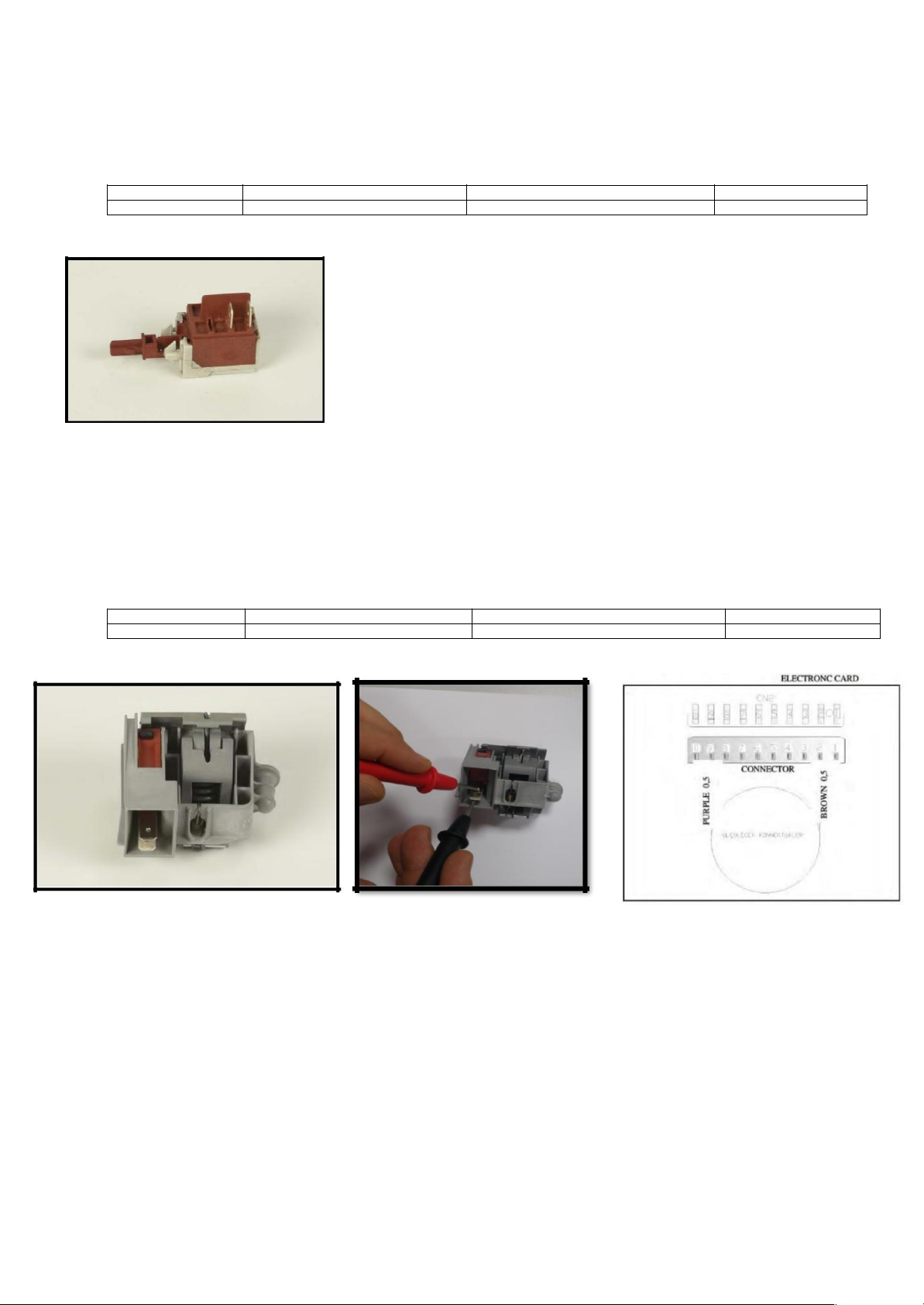
2.6 DRAIN PUMP
From the electronical Card:
Above sketch show the connectors of the drain pump on the electronical card. Probes of the tester should be
applied on to the related connectors.
From the component:
Probes of the tester should be applied on the related connectors as shown on the pictures.
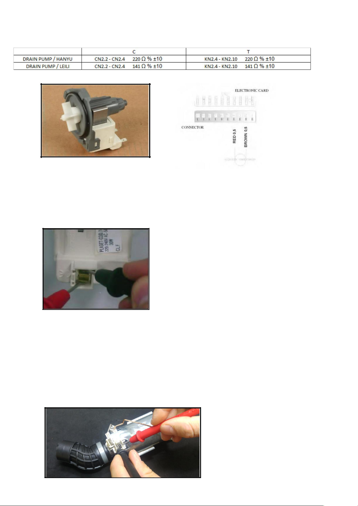
2.7 HEATER
It can’ be measured from the electronıcal card.
From the component:
7

2.8 NTC
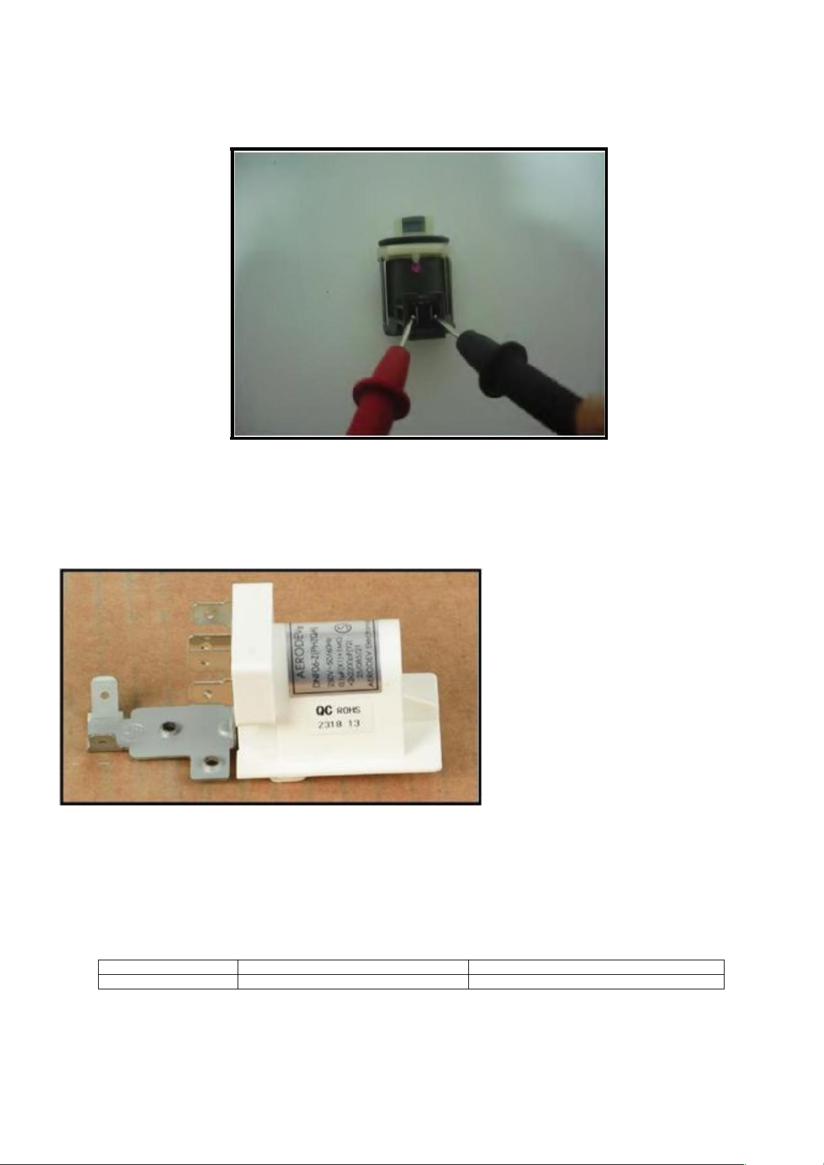
2.9 PRESSURE SWITCH
From the electronical card:
C
T
PRESSURE SWITCH
CN2.10 - CN2.2
0 Ω
KN2.9 - KN2.10
0 Ω
Full fıll water
∞Ω
∞Ω
No water
From the component:
8

2.10 DIVERTER
From the electronical Card:
Sketch above show the connectors of the diverter on the electronical card. Probes of the tester should be
applied on to the related connectors.
From the component:
Probes of the tester should be applied on to the related connectors as shown on the pictures.
2.11 WATER INLET VALVE
Single inlet and single outlet standard single coil selenoid valve.
From the electronical card:
C
T
WATER INLET VALVE
CN2.6 - CN2.9 4200 Ω ± %10 (20°C)
KN2.6 - KN2.8 4200 Ω ± %10 (20°C)
9

Above sketch show the connectors of the water inlet valve on the electronical card. Probes of the tester should
be applies on to the related connectors.
From the component:
Probes of the tester should be applied on to the related connectors as shown on the pictures.
2.12 REGENERATION VALVE
From the electronical card:
C
T
REGENERATION VALVE
CN2.2 - CN2.7 3560 Ω ± %10(25°C)
KN2.2 - KN2.10 3560 Ω ± %10(25°C)
10
Above sketch show the connectors of rhe regenaration valve on the electronical card. Probes of the tester
should be applied on to the related connectors.
From the component:
2.13 PARASITE FILTER
2.14 TURBO FAN MOTOR
From the electronical card:
C
T
FAN MOTOR
CN 6.2 - CN 2.9
KN 6.2 - KN 2.8
11

Above sketch shows the connectors of the fan motor on the electronical card.
From the comonent:
2.15 RINSE AID SENSOR
From the electronical card:
C
T
RINSE AID SENSOR
CN 5.3 - CN 5.2
0Ω NO RINSE AID
KN 50.8 - KN 50.9
0Ω NO RINSE AID
RINSE AID OFF
∞Ω THERE IS RINSE AID
∞Ω THERE IS RINSE AID
RINSE AID ON
12
Turbo fan resistance value: 265 ± %10 Ω (The resistance of the torbo fan is measured with the resistor switch).

Below sketch shows the connectors of the rinse aid sensor on the electronical card.
From the component:
Probes of the tester should be applied on to the relatde connectors as shown on the pictures.
2.16 SALT SENSOR
Salt sensor can also be measured from the water softener when the salt sensor assemblied on the water softener.
From the electronical card:
C
T
SALT SENSOR
CN5.1 - CN5.2
0 Ω NO SALT
KN50.10 - KN
0 Ω NO SALT
Measure just on the
∞Ω THERE IS SALT
50.11
∞Ω THERE IS SALT
electronıc
Sketch above show the connectors of the salt sensor on the electronical card. Probes of the tester should
be applied on the related connectors.
13
From the component:
2.17 POWER CORD
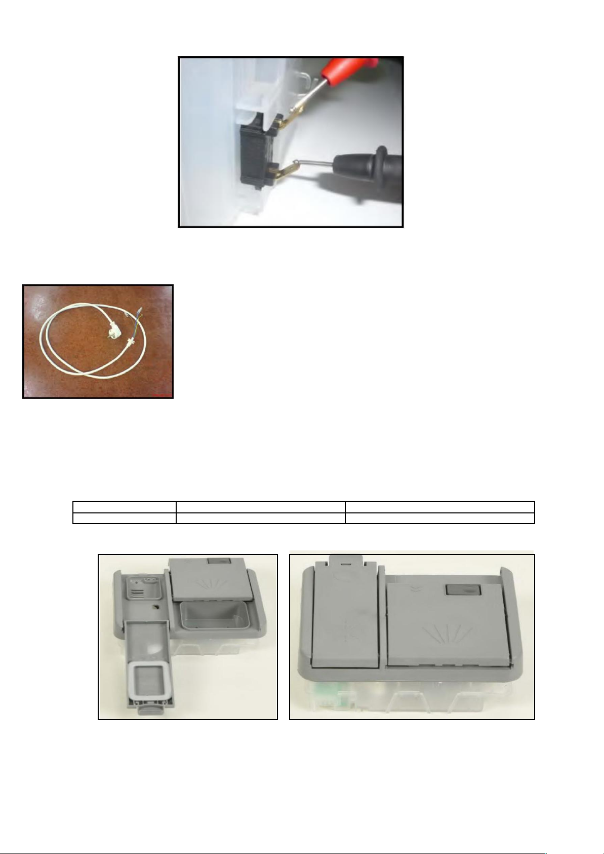
2.18 DETERGENT / RINSE AID DISPANSER
It can’t be measured from the electronical card:
C
T
DETERGENT DISPENSER
2300 Ω ±%10 (25 C°)
2300 Ω ±%10 (25 C°)
14

3.INTERFACE AND HARDWARE
Apart from the on-off switch that is a separate component, the UI includes:
“Selection program” button;
4 program LEDs;
“Salt” LED;
“Rinse” LED;
“End” LED.
D1 UI
3.1 D1 UI (D13_2):
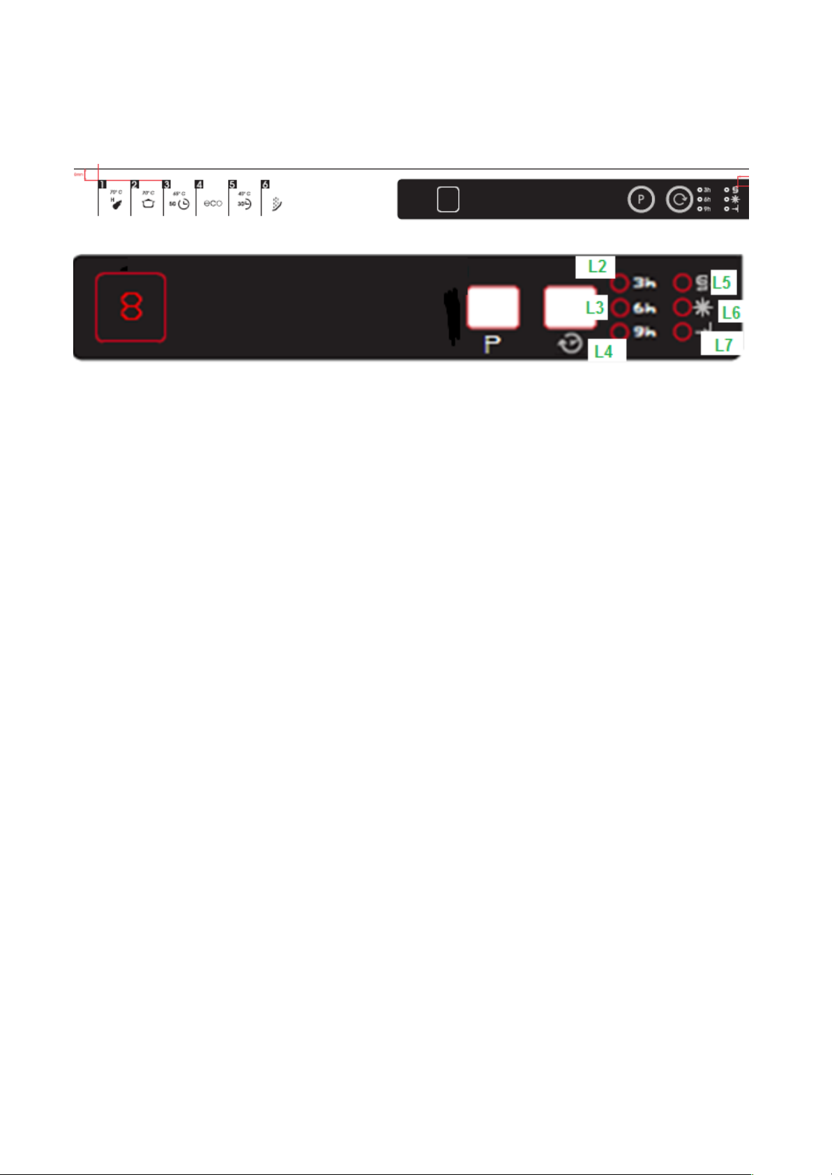
3.2 D2 UI (D21_1) :
Apart from the on-off switch that is a separate component, the UI includes:
“Selection program” button;
5 program LEDs;
“Salt” LED;
“Rinse” LED;
“End” LED;
“Start delay selection” button, 3-LEDs bar (the start delay function is
incremental, i.e. without “counting during Power Fail”).
D2 UI
Note: Auto program works if turbidty is present instead of ıntensive program.
15
3.3 D22_1:
Same as D21_1. Also hyigene program is added.
“Selection program” button;
“Salt” LED;
“Rinse” LED;
“End” LED;
Note: Auto program works if turbidty is present (instead of ıntensive program.)
Program sequences:
p1-hygiene 70 C
p2-ınt 70C
p3-super50
p4-eco
p5-quick 30
p6-prewash
3.4 D4 UI (D41_2,D42_2):
Apart from the on-off switch that is a separate component, the UI includes:
“Selection program” button;
2.5 digit (programs & delay);
“Salt” LED;
“Rinse” LED;
“End” LED;
“Start delay selection” button, 3-LEDs bar (the start delay function may be absolute, i.e. with “counting during
Power Fail” by RTC).
“Half load selection” button, with 2 LEDs;
“PW selection” button, with 1 LED;
“Tab selection” button, with 1 LED.
16

3.5 D50 UI (D12_7)
Apart ON/OFF switch that is a separate component interface includes:
3.6 D50 (D13_7)
3.7 D51 UI (D22_7)
Apart from the on-off switch that is a separate component, the UI includes:
“Selection program” button;
1 digit (programs);
“Salt” LED;
“Rinse” LED;
“End” LED;
“Start delay selection” button, 3-LEDs bar (the start delay function is incremental, i.e. without “counting during
Power Fail”); “Half load selection” button, with 1 LEDs.
17
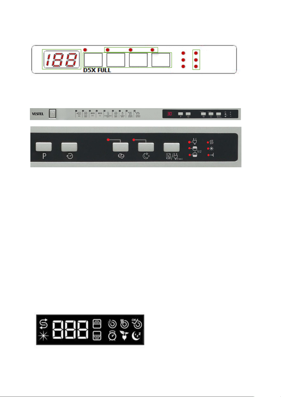
3.8 D5X Full
16
3.9 D45 with water recovery tank
Apart from the on-off switch, there is a separate component, the UI includes:
“Selection program” button;
2.5 digit (programs & delay);
“Salt” LED;
“Rinse” LED;
“End” LED;
“Start delay selection” button, 3-LEDs bar (the start delay function may be absolute, i.e. with “counting
during Power Fail” by RTC). “Half load selection” button, with 2 LEDs; Energy save option is activated/
deactivated by pressing half load button for 3”
“Tablet selection” button, with 1 LED.
“Extra silent selection” button, with 1 LED.
Front Display of D45
18
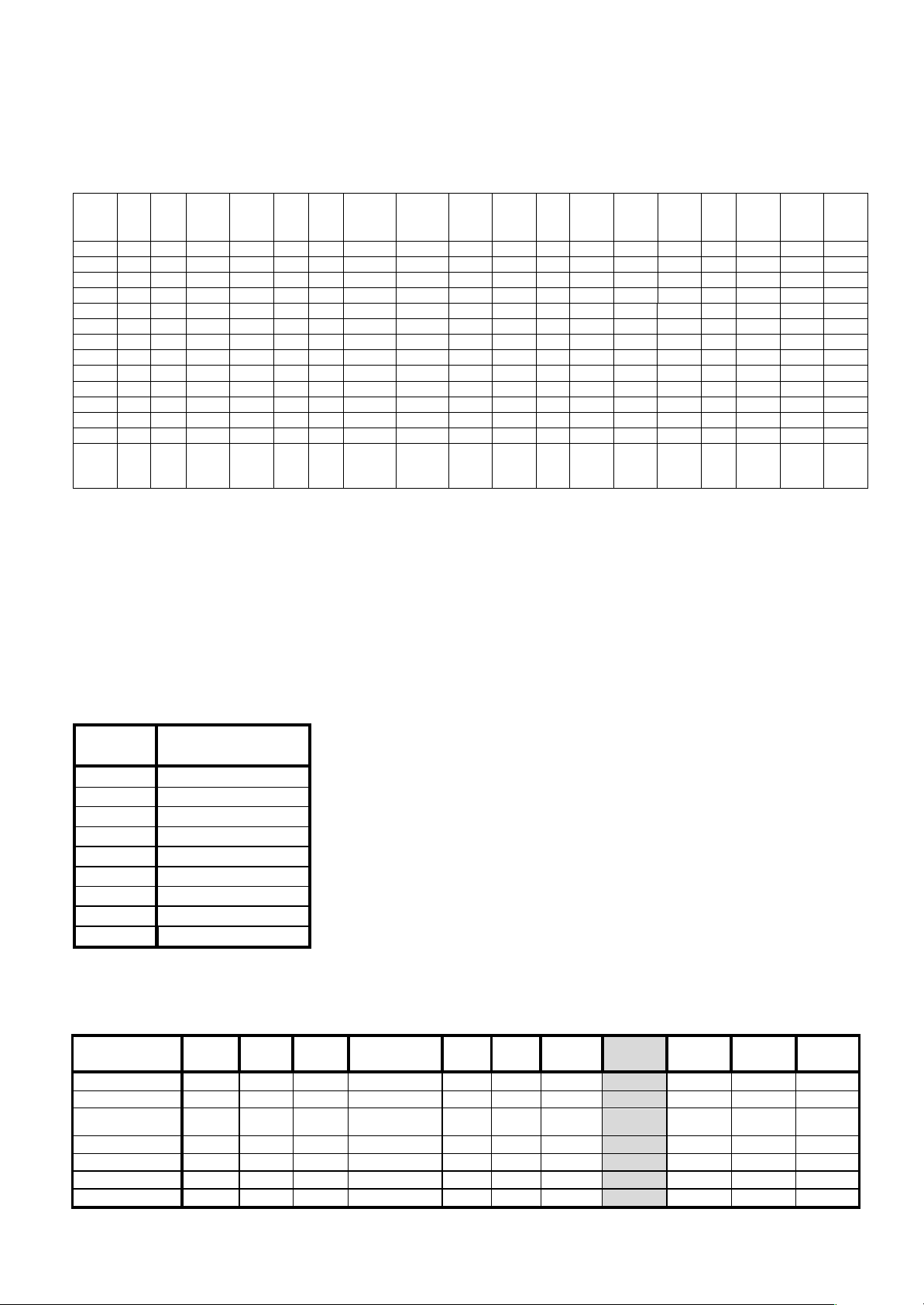
4. WASHING PROGRAMS ( 60&45 CM)
4.1 Washing program Cross Table
Model PRE
WH
QUIC
K 30’
DELCAT
E 40 C
ECO 50
C
ECO
5.4lt
DALY DUAL
PRO
WASH
SUPER
50’
SUPER
55’60 C
HYGIEN
E 60 C
INT
65
C(AU
TO)
INTNSI
VE
70C
EXTRA
HYGIEN
E70C
A.DEL A.NO
R
A.INT Bardak
+21/30
14’
D13_2 x - - x - - - x - - x - - - - - -
D14_5 - - - x - - - x - - - - - - - - X/X X
D21_1 x x - x - - - x - - - x - - - - -
D22_1 x x - x - - - x - - x x - - - -
D41_2 x x - x - - - - x x - - x x x x -
D42_2 x x - x - - - - x x - - x x x x -
D45 - X - X X - X X - X - - - X - X - X
D41_5 - - - x - - - x - - - - - - - - X/X X
D12_7 x - - x - - - - - - x - - - - - -
D13_7 x - - x - - - X - - x - - - - - -
D21_7 x x - x - - - x - - x - - - - - -
D22_7 x x - x - - - x - - x - x - - - -
D32_7 x x x x - x - x - - x - x - - - -
D41_7
-
D42_7
x x - x - - - x - - - - x x x x -
X = present
- = not present
* Vers. D4: Auto Delicate 30/50 C
* Vers. D4: Auto Normal 50/60 C
* Vers. D4: Auto Intensive 60/70 C
In D4 model if PW option is selected: (Prewash+Hygiene ) → Hygiene 60 C becomes Extra Hygiene70 C program.
Programme sequence
Program
number
D45
1 Mini 14’
2 Quick 30’
3 Eco 50°C
4 Eco 5.4lt
5 Dual Pro Wash 60°C
6 Super 50’ 65°C
7 Hygiene 60°C
8 Auto Delicate 30°C-50°C
9 Auto Intensive 50°C-70°C
Options & models:
Option D13_2 D14_5 D21_2 D41_2/D42_2 D45 D41_5 D12_7 D13_7 D22_7 D32_7 D41_7-
D42_7
PW Button - - - X - - - - - - -
Delay Timer - - x X X - - - x X x
Half load - - - X(3 mode) X(3
mode)
X(3
mode)
- - X(1mode) X(1mode) X(3 mode)
Tablet - - - x X - - - - x x
Energy Save X
Extra Silent X
Buzzer x x x x X x x x x x x
19

5. WASHING SPECIFICATIONS AND PROGRAMS
5.1 Starting of the program:
-After the first power on, until pressing any button display shows two dashed lines (“--“, justified to the right) , than
if pressing any button the (default program ECO) is shown at every turn. ( Ex: 3secs P3, 1sec 188).
- When the dishwasher is powered off and on again the last executed program and options are not visualized on
screen anymore. Each energized of the machine, Eco program is set to as default and the options that are chosen
before(delay start,tablet,half load etc.. will be cancelled due to ecodesign regulations.
-The selected washing program is visualized in F1 and F2 by washing LEDs and in F4 by display (P+number; from P1
to P8); in F4 the duration of the program and its P+number are altenatively visualized (3” Pn, 1” time). At any
pressure of “Program button” the number of program is incremented, and when it reaches P8 restarts from P1. When
the program starts, the remaining time of such a program is visualized in the same format.
- During the wash, if the user changes the program by pressure of program button:
if the new program has a corresponding step, display shows the time of the new program
without the passed time.
-Before the washing program starts, if the user pushes the delay button, delay led will be on at both displays, the
delay time occurs in the format “nnh” (max 19h); when the program starts, both displays visualizes the
remaining delay time in the same format (1 hour steps).
- When a Failure is present the code of the failure is visualized at the display. (Ex: “F2” with all leds blink.) If it
has not display, visualized the error codes by blinking dedicated LEDs.
-In machines having screen ,When the Service Dept. runs the Salt Set program, “SL” is visualized for 2” and
then the last set value is shown (the default value “L3” for the fist time). Without screen models,directly
shown the error code with dedicated leds.
5.2 Selecting and Running of program:
- While choosing the program, dishwasher door must be open. If user tries to command the dishwasher while
the door is closed the buzzer will be activated for 1sec to show that it is not allowable.
- By pressing the program button, suitable program is choosen.
- Program starts without delaying after closing the door (if the measured temperature is less than 45°C).
- When program starts the remaining time is visualized in the same format.
Note1: During program in the display at every 3secs, the Remaining time will be shown at the
display . ( Ex: 3secs P3, 1sec 188).
5.3 Opening-closing the door during the program execution
After the start, if the user opens the door, all the functions of the dishwasher stop.
The respective program LED is fix ON, in F4 the display shows altenatively the program number and the
duration of the program (3” Pn, 1” time).
-When the door is closed, the program continues. Washing program re-starts without delaying”. (if the measured
temperature is less than 45°C) (This is valid for also ON/OFF condition.)
-Wait 8” before restart program if temp. is equal or more than 45 C. (This is valid for also ON/OFF condition.).
-During a Dry step. At the power on or open /close the door , the program goes to ends for all models.
- If temp. is equal or more than 45 C when user open/close the door or turn off/on machine or pause/start
machine, wait 8” before restarting the program.
20

5.4 Memorization during cycles
During washing program steps and options are stored in memory and a flag “cycle in progress” is set. At the
end of the program, the flag “cycle in progress” is reset,and a new cycle can start.
5.5 Power Fail:
During washing programs, phase and options are stored in memory and a flag “cycle in progress” is set.
If a power fail occurs, then:
during a Delay Start: at the new power on, the program consumes the remaining time;
during a Drain + Fill step: at the new power on, the program continues from the point where it remains.
during a Wash step: at the power on, the program consumes the remaining time;
during a Heating step: at the power on, the program continues heating up to the desired temperature, and
the time out for the heating restarts to the beginning (water could be cold again);
- During a Dry step, At the power on the program also ends.
- If machine has not a display and when you open /close the door, the program also ends.
It is possible that the power fail occurred when a regeneration cycle is requested. If it occurs:
- During the first two step of a salt regeneration cycle ( 60” REGVALVE = ON or 60” REGVALVE+DRAIN ON):
at the power on washing program will continuos.
- After the first two step of a salt regeneration cycle: at the power on the washing program will end and the
resin wash will be performed at the beginning of the next washing cycle.
Means that;
Until the first pause step(regeneration valve+drain+480” pause), if Power OFF/ON or Door Open/Close
happens, program resumes. If Power OFF/ON or Door Open/Close happens in the second pause step and the
other steps, program ends. In that case, resin washing is executed at the beginning of the next step.
5.6 Modification of a program
- During a program, open the door;
- Select a new program by pressing the program button;
- Closing the door, the machine will follow the new program steps.
5.7 Modification of a program with opening the door:
- The program continues with the flow program but with the parameters (temperature, times) of the new program.
- During a Heating step,if the user change the program, The time out for the heating restart to the beginning
(water could be cold again).
- If user changes program during washing,the duration is adapted. Namely, machine must go to
the same step in the algorithm and show the duration of the related step of the new program.
- Adding options such as tablet, hygiene, half load to the drying process should not change time displayed
on the display . However, when the extra drying option is added, the display time may change depending on
the drying time.
- When the tablet option is selected, it is desirable that the main wash be 55°C in any case.
5.8 Cancelling of a program (Reset)
- During a program, open the door.
- Press program button for 3sec.
- The end led starts to blink at the display and display shows ‘’1” to indicate that cancelling is ready.
- After 3sec of closing the door, draining will be executed.
21

- At the end of the reset, the End led will be ON and the buzzer will be activated (1sec sound, 4sec wait
until total time 21sec is completed [total 5 bip sound] until 15 min passed) If the door is not opened by the
user, the activation of the buzzer will continue at ever each 5min passed (with 5 time bip in 21sec as
indicated above until 15 min passed).
- After the end of the program when door is opened, the buzzer activation will be ended. (End led ON)
- If user cancels the program when the door is closed and presses program button to select another program,
this another program starts at the beginning when the door is closed.
- Drain pumps never operates if the door is open.
5.9 Termination of a program:
When the program is completed, End led will be on and the buzzer will be activated (1sec sound, 4sec wait
untill total time 21sec is completed [total 5 bip sound]) If the door is not opened by the user the activation of
the buzzer will contiune until 15 min passed which means that in first 5min : (1sec sound + 4sec wait) x5)
signal / In the second 5min: (1sec sound + 4sec wait) x5) signals and in the last 5min: (1sec sound + 4sec
wait)x5) signals, then the routine is stopped...
After the end of the program when door is opened, the buzzer activation will be ended. (End led ON).
5.10 “Rinse-aid” absence and “Salt” absence visualization
Two LEDs for rinse-aid absence and salt absence are present.
In D1, D2,D12-7,D22-7,..... models they are drived by hardware.
5.11 Program selection and starting while door is closed:
Whereas, in model D4, they are driven by the microcontroller.
- While the door is closed, it will not be possible to select a program or an option and start to program.
- If any button is pressed during the door is closed, the buzzer will be activated for 1 sec.
5.12 Opening door during a regeneration cycle:
It is possible that the door is opened during a regeneration cycle. If it occurs:
- During the first two step of a salt regeneration cycle ( 60” REGVALVE = ON or 60” REGVALVE+DRAIN ON): at
the door re-close the washing program will continues.
- After the first two step of a salt regeneration cycle: at the door re-close the washing program will end and the
resin wash will be performed at the beginning of the next washing cycle.
5.13 OPTION SELECTION:
5.13.1 Selecting and Starting a program with Delay Start:
While Door is Open, by pressing the delay start button, the required delay value is chosen. (ex:19h).
When pressing to the delay start button, delay start button led is on at the display (until expired or
cancelled delay time).
Note1: First choosing the program then selecting the delay value is also possible.
Note2: Every 3secs, the Delay value will be shown at the displays ( Ex: 3secs P3, 1sec 19h).
- After 3sec ıf the user closes the door, the program with Delay will be in operation.
- Buzzer will be activated (1sec) if user open the door and try to select a delay time during the wash.
5.13.2 Cancelling the Delay Start:
- During the delay time duration of a program.
- Open the door.
- By pressing the Delay start button, the delay start option can be canceled. (or can be changed with the new
one)
- After cancelling the delay time value, after closing the door. The program will start after 3sec.
22
This manual suits for next models
15
Other SOGEDIS Dishwasher manuals


Popular Dishwasher manuals by other brands


Haier
Haier DW12-TFE3-F Instructions for use

Electrolux
Electrolux ESF4600ROW user manual

Amica
Amica GSP 544 910 E operating instructions

Alico
Alico Champion CH-44 Installation/operation manual with service replacement parts

Silvercrest
Silvercrest SGW 860 A1 quick start guide

Magic Chef
Magic Chef MCSCD6W1 user manual


