SOGEDIS T41 Series User manual

SERIES T41-T42-T43
1

CONTENT
1.BARCODE STICKER CODE EXPLANATION........................................................................................................................3
2. ELECTRICAL COMPONENTS AND MEASUREMENTS .................................................................................................................4
3.INTERFACE AND HARDWARE......................................................................................................................................................15
4.WASHING PROGRAM.........................................................................................................................................................................15
5.WASHING SPECIFICATIONS AND PROGRAMS..........................................................................................................................16
7.SOFTWARE REQUIREMENTS...................................................................................................................................................52
8.TEST PROGRAMS..........................................................................................................................................................................54
9.MEASUREMENT THE WATER HARDNESS.............................................................................................................................61
11. REPAIR TECHNIQUES COMP..................................................................................................................................................65
12.DISASSEMBLY...............................................................................................................................................................................66
6.OPTIONS...........................................................................................................................................................................................28
2
10. FAILURE CODES (POSSIBLE PROBLEMS)....................................................................................................................61
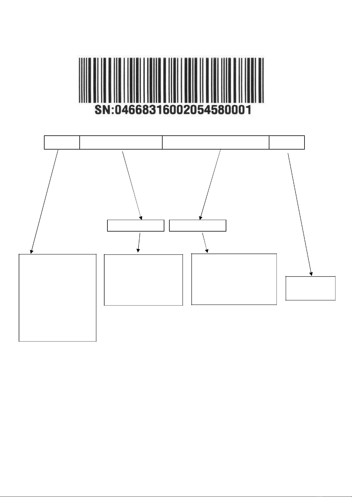
1.BARCODE STICKER CODE EXPLANATION
04
668316
00205458
0001
PRODUCT CODE
ORDER CODE
01- W/O CARTOON;
W STRİP
02- W/O CARTOON;
W/O STRİP
03- W CARTOON ;
W STRİP
04- W CARTOON ;
4- LANE
05- W/O CARTOON ;
4-LANE
In front of this numbers
“10” should be added for
an product code:
668316 - 10668316 is
the product code.
In front of this numbers “55”
should be added for an order
number:
00205458 - 5500205458 is
the order number.
Increases by
numeratically
3

2.ELECTRICAL COMPONENTS AND MEASUREMENTS
2.1 ON / OFF SWITCH
It can’t be measured from the electronical card.
C
T
DOOR SWITCH
CN2.9 - CN2.2 0 Ω
KN2.8 - KN2.10 0 Ω
Door is close
2.2 DOOR LOCK
It is a mechanical lock/release system that is closing the door, supplying the connection of electrical parts in
the machine and cutting off the connection.
From the electronical card:
C
T
DOOR SWITCH
CN2.9 - CN2.2 0 Ω
KN2.8 - KN2.10 0 Ω
Door is close
2.3 CIRCULATION PUMP
Single direction, single phase, asynchronus and two pole. It turns opposite clock direction. It is assambled
to the basement with rubber hangers.
From the electronical card:
You can only measure the primary winding value from the electronical card. Resistance value of the
primary winding must be;
4

C
T
CIRCULATION PUMP
CN2.3 - CN2.9
KN2.3 - KN 2.8
Primary winding
Secondary winding (from
the component)
Above sketch show the connectors of the washing pump on the electronical card. Probes of the tester should
be applied on to the related connectors.
From the component:
A) B)
A) Measurement of the primary windings of the washing pump.(118.2-135.9 Ω)
B) Measurement of the secondary windings of the washing pump (white cable –blue cable)(117.9-135.6 Ω)
Probes of the tester should be applied on to the related connectors as shown on the pictures.
2.4 FLOATER
From the electronical card:
C
T
FLOATER
CN2.1 - CN 2.5
0 Ω
KN2.5 - KN 2.10
0 Ω
Mıcroswıtch ıs ınactıve (no
water ) mıcroswıtch ıs actıve
∞Ω
(MICROSWITCH)
CN2.1 - CN 2.4
∞Ω
KN2.4 - KN 2.5
(there ıs water)
5
This manual suits for next models
11
Table of contents
Other SOGEDIS Dishwasher manuals


