Solair F2000 Manual
SOL-AIR SYSTEMS INC.
The Sol-Air F2000
Operations &
Maintenance Man al
Serial Number Inspected

Version 1.5 (121506)
Operations &
Maintenance Manual
Sol-Air Systems Inc.
1671A Cary Road
Kelowna, BC V1X 2C1
hone 250.763.7034 • Fax 250.763.7023

Version 1.5 (121506)
Table of Contents
The Sol-Air Advantage Page 1
Warnings
Page 2
Operating Instructions
Page 3
The Control Panel Page 3
System Placement Page
Caring for the F2000
Page 6
Parts Replacement Procedures Page 7
UV Lamps Page 7
Fuses Page 9
Specifications Page 10
Parts List Page 10
Contacting Sol-Air Page 11
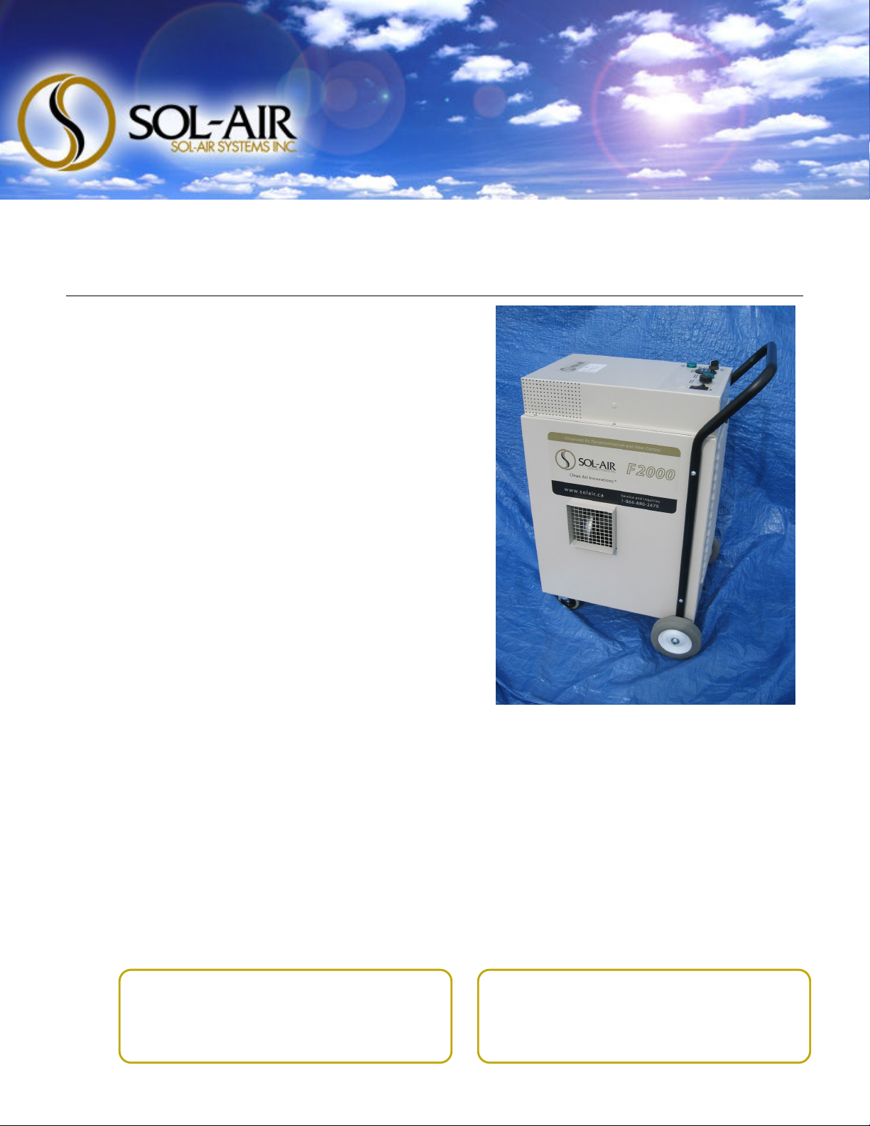
The F2000 Air Decontamination System

F 2 0 0 0 O P R A T I O N S & M A I N T N A N C
Version 1.5 (121506)
1
11
1
“North Americans spend nine o t of every ten ho rs indoors, and
indoor air commonly contains higher concentrations of airborne
chemical contaminants and pathogenic microbes than o tdoor air.
Biological and chemical terrorism, sick b ildings, toxic molds, and
epidemics of asthma and allergies, all have made the iss e of healthy
air critical. Removing biological pathogens and toxic chemical
compo nds from air — air decontamination — has been a recognized
need for decades.”
- Greg Lesavoy and Jordan Peccia, Ph.D., PE
Sol-Air systems decontaminate air, eliminating bacteria, vir ses, toxic molds and
chemicals, and h ndreds of npleasant odors ca sed by fire, smoke, mildew, flood
damage, chemical poll tion, spills, sewage back p, black water, standing gray
water, etc.
K Y A D V A N T A G S
Low Capital Costs
Low Operations Costs
Portable
Chemical-Free
Efficient Processing
Energy Efficient
Easy To Operate
Safe
Virt ally Maintenance-Free
The Sol-Air Advantage

F 2 0 0 0 O P R A T I O N S & M A I N T N A N C
Version 1.5 (121506)
2
22
2
DISCONNECT the nit from the electrical power so rce before
performing any maintenance on the nit.
DO NOT stand in water while operating the nit.
Ens re that the nit is NOT in water or has water contacting it while in
operation.
AVOID direct eye expos re to a lit UV lamp. Repeated or prolonged eye
expos re can ca se serio s eye inj ries. Wear UV absorbing safety glasses
when viewing UV lamps in operation.
AVOID direct skin expos re to a lit UV lamp. Repeated or prolonged skin
expos re can ca se serio s b rns and skin tiss e inj ries. Wear protective
clothing and shield exposed skin s rfaces.
AVOID handling the UV lamps immediately following operation of the
nit. UV lamps are HOT d ring operation of the nit and sho ld be
allowed to cool s fficiently before handling.
Do not BLOCK or otherwise obstr ct the path of the exha st airflow.
Maintain an UNOBSTRUCTED perimeter of at least 3 feet (1 metre) from
the exha st port.
Warnings
WARNING
DISCONNECT the system from
the electrical power source before
performing any maintenance on
the system.
F 2 0 0 0 O P R A T I O N S & M A I N T N A N C
Version 1.5 (121506)
3
33
3
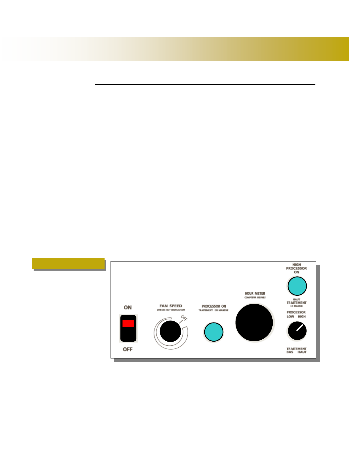
Figure 1
T H C O N T R O L P A N L
There are 2 indicator lights and 3 switches on the F2000 (Fig re 1 below.)
1.
AC Power Switch (With Red Indicator – T rns the power on/off and
indicates AC power to the fan and the Unit.
2.
Fan Speed Switch – Controls the speed of the fan and airflow thro gh
the system.
3.
Processor ON Indicator (Green – Indicate that the first UV Lamp is
processing.
4.
Hour Meter – Q artz non-reversible indicator of acc m lated ho rs of
se.
5.
HIGH Processor ON Indicator (Green – Indicates that the second
UV Lamp is processing.
6.
Processor Switch – LOW / HIGH. This Switch selects the intensity of
the process (n mber of lamps in operation).
1
2
3
5
6
4
Operating Instructions
F 2 0 0 0 O P R A T I O N S & M A I N T N A N C
Version 1.5 (121506)
4
44
4
O P R A T I N G T H F 2 0 0 0
P O W R O N
The main power for the machine can be switched on by switching the AC Power
Switch to the ON position. When the machine is switched on the red indicator light
on the switch will t rn on.
P O W R O F F
The main power for the machine can be switched off by switching the AC Power
Switch to the OFF position. When the machine is switched off the red indicator
light on the switch will t rn off.
F A N S P D
The F2000 is eq ipped with an Air Mover Blower Fan, which r ns between 100
and 1000 C bic Feet per Min te.
In the OFF position, the fan will not be operating. Rotating the Fan Speed Switch
controls the fan speed. When the switch is rotated clockwise from OFF, the fan will
be operating at its highest speed.
1. To slow down the fan, contin e to rotate the switch clockwise.
2. To increase the speed of the fan, rotate the switch co nter clockwise.
P R O C S S O R S W I T C H
The F2000 is eq ipped with 2 UV Lamps.
1. To operate the system with one lamp, t rn the Processor Switch to LO.
2. To operate the system with two lamps, t rn the Processor Switch to
HIGH.
There are two green indicator lights to indicate the stat s of the lamps within the
system.
F 2 0 0 0 O P R A T I O N S & M A I N T N A N C
Version 1.5 (121506)
5
55
5
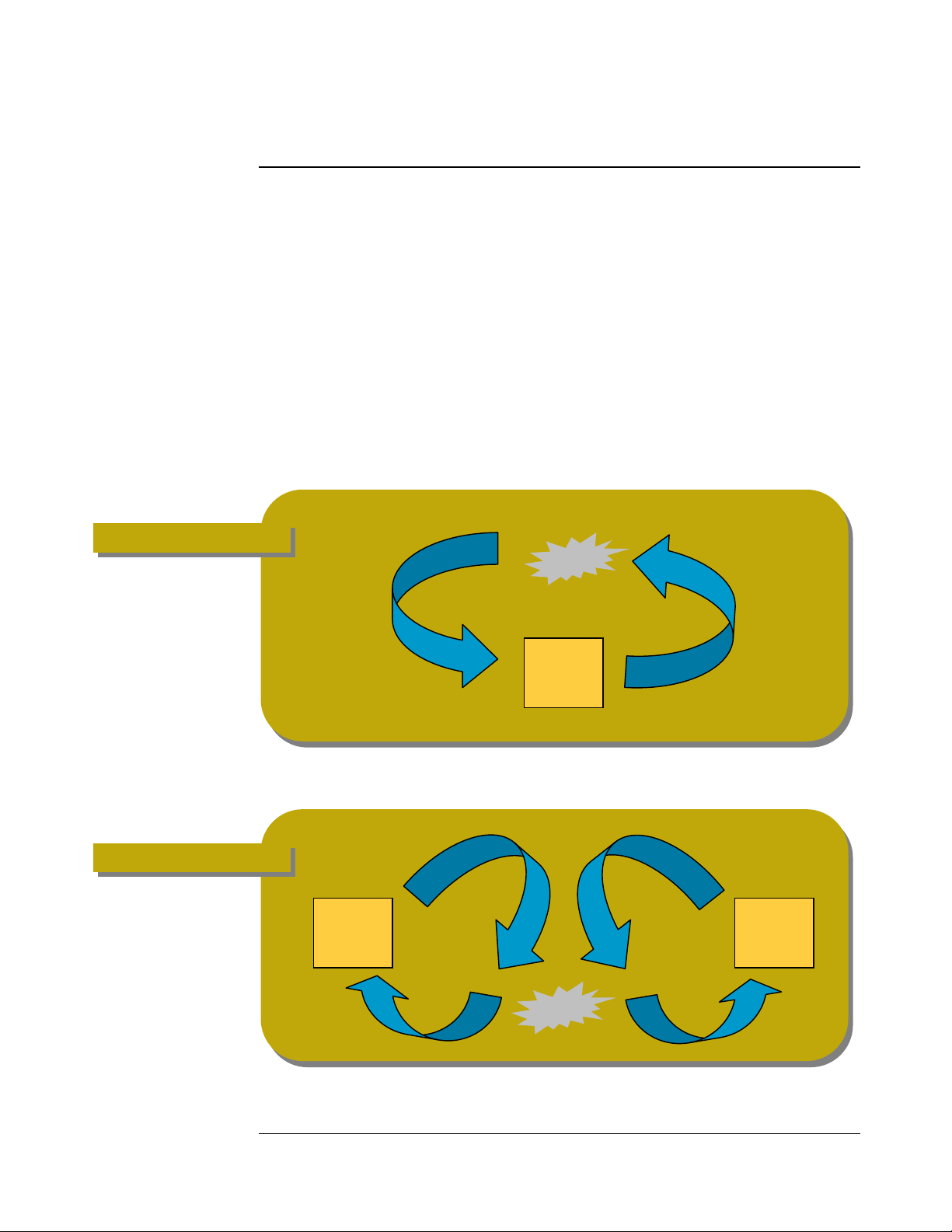
Figure 2
S Y S T M P L A C M N T
The manner in which yo position the Sol-Air system can make a big impact on its
efficiency. Yo may have to experiment a little to find the best position for the
system. Yo sho ld position the system as per Fig re 2 for efficient
decontamination.
If yo are sing two or more systems, place them so they blow into the
contaminated area to create a vortex. For example, if yo are sing two systems,
place one on each side of the effected area. (Fig re 3)
Keep all windows and doors closed d ring the treatment process, if
possible.
Figure 3
Sol-Air
System
Sol-Air
System
Sol-Air
System

F 2 0 0 0 O P R A T I O N S & M A I N T N A N C
Version 1.5 (121506)
6
66
6
Warning
DISCONN CT the unit from an electrical power source before
performing any maintenance on the unit.
S Y S T M C A S C L A N I N G
X T R I O R
The exterior of the machine can be cleaned with mild dishwashing detergent and a
clean cloth, and then rinsed with clean water. DO NOT se any all-p rpose
cleaners with harsh detergents or abrasives, as these may damage the decals and the
exterior finish. Care sho ld also be taken to avoid spraying or otherwise directing
detergent or water into or aro nd electrical components.
I N T R I O R
The interior walls of the UV lamp chamber can be cleaned in the same manner as
the exterior.
U V L A M P C L A N I N G
D ring UV lamp replacement (see UV Lamp Replacement) cleaning of the new
UV lamps is recommended to maintain peak lamp processing efficiency.
Fingerprints, sm dges, dirt and d st particles, etc. will interfere with the UV
radiation process and m st therefore be avoided.
To clean the UV lamps, se a 50/50 mixt re of r bbing alcohol and clean water on
a lint-free cloth (chamois recommended) and wipe the glass gently. Do not se any
type of commercial glass cleaner. Using another lint-free cloth (chamois
recommended) gently wipe the lamp ntil completely dry. Allow the lamp to dry
completely (20 min tes) before operating the system.

F 2 0 0 0 O P R A T I O N S & M A I N T N A N C
Version 1.5 (121506)
7
77
7
U V L A M P S
The expected life of the UV lamps may vary, depending on a n mber of factors
incl ding ambient operating conditions, b t will generally average 9,000 ho rs of
operation. The lamp does not b rno t like a reg lar incandescent b lb, b t slowly
becomes less effective. After the expected life, the lamp will no longer
decontaminate the air passing thro gh it effectively, and the lamp sho ld be
replaced.
Warning
DISCONN CT the unit from the electrical power source before
performing any maintenance on the unit. Allow 30 minutes for the
system and lamps to cool down before performing lamp replacement.
Note
The UV Lamp is packaged in its own Styrofoam box. The lamp is fragile and extreme
caution should be taken when handling. Use paper toweling or a clean cloth when handling
the lamp, so as not to get fingerprints on it. Fingerprints will inhibit the production of
ultraviolet light. If you do get fingerprints on the UV lamp, you can clean them off with a
soft, clean cloth lightly dampened with rubbing alcohol. Allow the lamp to dry before
installing and turning on the system.
U V L A M P I N S T A L L A T I O N
Step 1
a) Locate the rear (louvered) panel. Unscrew the
two (2) thumbscrews at the top and bottom of
the panel.
b) Remove the rear panel.
Step 2
a) Locate the front panel and unscrew the two
(2) thumbscrews at the top and bottom of the
panel.
b) Remove the front panel.
Parts Replacement Procedures

F 2 0 0 0 O P R A T I O N S & M A I N T N A N C
Version 1.5 (121506)
8
88
8
Step 3 – Lamp Removal
a) From the back of the system, hold the ceramic
base of the lamp and disconnect the plug from
the lamp.
b) Remove the lamp from the lower holding
clamp then the upper clamp. Remove the
lamp from the forward holding clamp.
Step 4 – Lamp Installation
Insert the new lamp from the front of the system.
Place the lamp into the forward clamp.
From the rear of the system, insert the lamp into
the upper clamp, then the lower.
Step 5
Connect the female plug to the 4-pin footing of the
lamp. The plug fits in only one direction. You may
have to rotate the plug 90 degrees.
Warning
DO NOT force the plug
into the pins.
Step 6
Test the system to ensure that both lamps are
operating. If a lamp is not lit, turn off the system
and disconnect the power and repeat steps 4 and
, then test the lamp again.
Warning
nsure that all users
in the vicinity of the
system are wearing
UV protective
eyewear. AVOID
prolonged direct
viewing of a lit lamp.
Step 7
Reinstall the rear (louvered) panel. Screw the two
(2) thumbscrews at the top and bottom of the
panel.
F 2 0 0 0 O P R A T I O N S & M A I N T N A N C
Version 1.5 (121506)
9
99
9
Step 8
Reinstall the front panel. Screw the two (2)
thumbscrews at the top and bottom of the panel.
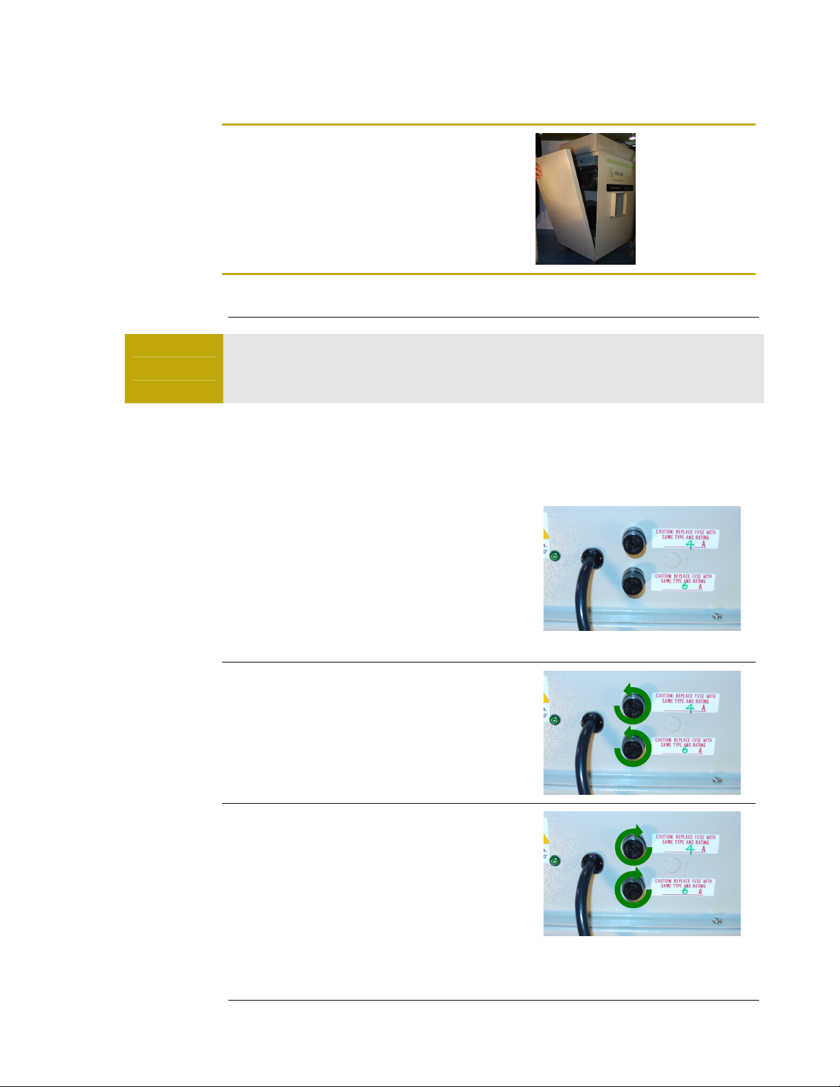
F U S S
Warning
DISCONN CT the unit from an electrical power source before
performing any maintenance on the unit.
NOTE: The fuses are Type CC sand fi ed s ow-b ow. See the parts ist for the
specifications.
F U S R P L A C M N T
Step 1
The F2000 contains two fuses: a main fuse and a
fan fuse. The main/lower fuse (6A) protects the
electrical complements of the entire system and
the fan/upper fuse protects the electrical
components of the fan.
Step 2
To remove either fuse, turn the fuse counter-
clockwise while pressing in.
Step 3
To insert a new fuse, press the fuse in and turn
clockwise

F 2 0 0 0 O P R A T I O N S & M A I N T N A N C
Version 1.5 (121506)
10
1010
10
S O L - A I R F 2 0 0 0 S P C I F I C A T I O N S
Dimensions:
14” x 20” x 30”
(3 .6 x 0.8 x 76.2 cm)
Weight:
7 lbs (34.1 kg)
Power Requirements:
120V, 4.0A
Starting:
Selector Switch, with indicator light
Fan Contro :
Variable Speed Control 100 to 1000 cfm
Meter:
1/10 Quartz Hour Meter
P A R T S L I S T
P A R T D S C R I P T I O N P A R T N U M B R
10" Dua Zone UV U-Lamp 30-0011
E ectronic Ba ast 30-0006
Fan Speed Contro Switch (Variab e Speed Switch) 32-0006
Quartz Hour Meter 32-0009
ON / OFF Switch (2 Position) 32-0001
4 Amp Fuse (S o-B ow) 30-0001
6 Amp Fuse (S o-B ow) 30-0002
Specifications

F 2 0 0 0 O P R A T I O N S & M A I N T N A N C
Version 1.5 (121506)
11
1111
11
For replacement parts, warranty service, or any q estions regarding the operation and
maintenance of yo r Sol-Air nit, please contact s at:
Contacting Sol-Air
Table of contents
Other Solair Air Cleaner manuals


