Solar Mobility liberator Service manual
Solar Mobility LLC
The Liberator
Service Guide
This Service Guide contains:
Troubleshooting Replacement
Instructions Illustrated Parts
Diagrams

www.solarmobilityinc.com
Contact Information
SolarMobilityLLC.
1426 East 3rd Ave,
Kennewick, WA 99336
Phone: 509-851-3611
Fax: 509-396-9051Email:
E-mail sales@solarmobilityinc.com

www.solarmobilityinc.com
Table of Contents
About the Liberator Service Guide .............................................................................................................................. 4
LIBERATOR COMPONENTS ..................................................................................................................................................... 4
Scenario 1: Press the on/off button and the LED Array does not light up. (Shark) ............................................... 9
SCENARIO 2: Batteries Will Not Charge (Shark Charging Test) ........................................................................ 10
Joystick LED Array DIAGNOSTICS (Shark) ......................................................................................................... 11
LED ARRAY “CHASE” LEFT-TO-RIGHT FOLLOWED BY A STEADY DISPLAY ......................................................... 11
FLASH CODE #1 – POSSIBLE STALL TIMEOUT OR USER ERROR .............................................................................. 11
FLASH CODE #2 – BATTERY FAULT ..................................................................................................................................... 11
FLASH CODE #3 LEFT MOTOR FAULT ................................................................................................................................ 11
FLASH CODE #4 RIGHT MOTOR FAULT ............................................................................................................................. 12
FLASH CODE #5 LEFT PARK BRAKE ................................................................................................................................... 12
FLASH CODE #6 RIGHT PARK BRAKE FAULT .................................................................................................................. 12
FLASH CODE #7 - SHARK CONTROLLER MODULE FAULT ......................................................................................... 12
FLASH CODE #8 - SHARK POWER MODULE FAULT FLASH ........................................................................................ 12
CODE #9 - SHARK COMMUNICATIONS FAULT FLASH ................................................................................................. 12
CODE #10 - UNKNOWN FAULT .............................................................................................................................................. 12
Scenario 1: Press the on/off button and the LED Array does not light up. (A Series) ......................................... 14
SCENARIO 2: Batteries Will Not Charge (A Series) .............................................................................................. 15
Joystick LED Array DIAGNOSTICS (A Series) ..................................................................................................... 16
LED ARRAY "CHASE" LEFT-TO-RIGHT FOLLOWED BY A STEADY DISPLAY ......................................................... 16
FLASH CODE #1 - POSSIBLE STALL TIMEOUT OR USER ERROR ............................................................................... 16
FLASH CODE #2 - BATTERY FAULT ...................................................................................................................................... 16
FLASH CODE #3 LEFT MOTOR FAULT ................................................................................................................................ 16
FLASH CODE #4 RIGHT MOTOR FAULT ............................................................................................................................. 16
FLASH CODE #5 LEFT PARK BRAKE ................................................................................................................................... 17
FLASH CODE #6 RIGHT PARK BRAKE FAULT .................................................................................................................. 17
FLASH CODE #7 - INTERNAL USER FAULT ........................................................................................................................ 17
FLASH CODE #8 - CONTROLLER FAULT ........................................................................................................................... 17
FLASH CODE #9 - INTERNAL COMMUNICATIONS FAULT ............................................................................................ 17
FLASH CODE #10 - UNKNOWN FAULT ................................................................................................................................ 17
REPLACEMENT INSTRUCTIONS ........................................................................................................................ 18
DRIVE WHEEL ........................................................................................................................................................................... 18
FRONT CASTER ......................................................................................................................................................................... 19
DRIVETRAIN (MOTOR AND GEARBOX) ............................................................................................................................ 20
POWER MODULE ...................................................................................................................................................................... 22
Illustrated Parts Diagrams ........................................................................................................................................ 23
SHROUD ASSEMBLY ............................................................................................................................................................... 23
ASSEMBLY 100 ........................................................................................................................................................................... 25
ASSEMBLY 200 .......................................................................................................................................................................... 26
ASSEMBLY 300 .......................................................................................................................................................................... 28
FRONT RIGHT CASTER ARM ASSEMBLY
....................................................................................................................... 30
FRONT LEFT CASTER ARM ASSEMBLY
.......................................................................................................................... 32
REAR RIGHT CASTER ARM ASSEMBLY
......................................................................................................................... 34
REAR LEFT CASTER ARM ASSEMBLY
............................................................................................................................ 36
RIGHT ARMREST ASSEMBLY ............................................................................................................................................. 38
LEFT ARMREST ASSEMBLY
................................................................................................................................................ 40
ELECTRONICS AND MISCELLANEOUS (SHARK) ............................................................................................................ 42
ELECTRONICS AND MISCELLANEOUS (A SERIES) ......................................................................................................... 43
Illustrated Parts Diagrams Solar Companion ......................................................................................................... 44

www.solarmobilityinc.com
About the Liberator Service Guide
This service guide provides you with the information necessary to troubleshoot the Solar Mobility LLC. Liberator
equipped with the Dynamic Shark REMA and REMD and the A-Series controllers. The troubleshooting scenarios in
this manual consist of procedures that enable you to systematically trace and correct faults in the system.
Before troubleshooting, check the following:
•Make sure that the circuit breaker is reset.
•Visually check terminals for corrosion. Check wires for missing insulation.
•Make sure that the batteries fully charged and are in good working order. When possible, keep sets of
known good batteries of various ratings in your shop at all times. The Liberator uses either 35AH (U1) or
55AH (NF-22) batteries. Problems that surface during troubleshooting are often due to the fact that the
batteries are not fully charged or cannot hold their charge.
•Make sure that the electrical connections are secure. Unplug the connectors and make sure all of the pins
are seated properly. Push the pins back into the connector housing if necessary. Make sure that the battery
terminals are tight.
NOTE: If you get to a point during troubleshooting where you cannot continue, call tech support.
LIBERATOR COMPONENTS
The Liberator is battery-operated power chair controlled by a Dynamic control system. The Dynamic control
system monitors the systems and display flash codes on the LED Array when it detects a fault in the system. The
Liberator was designed to operate with between 18 – 24 volts (V) of direct current (DC).
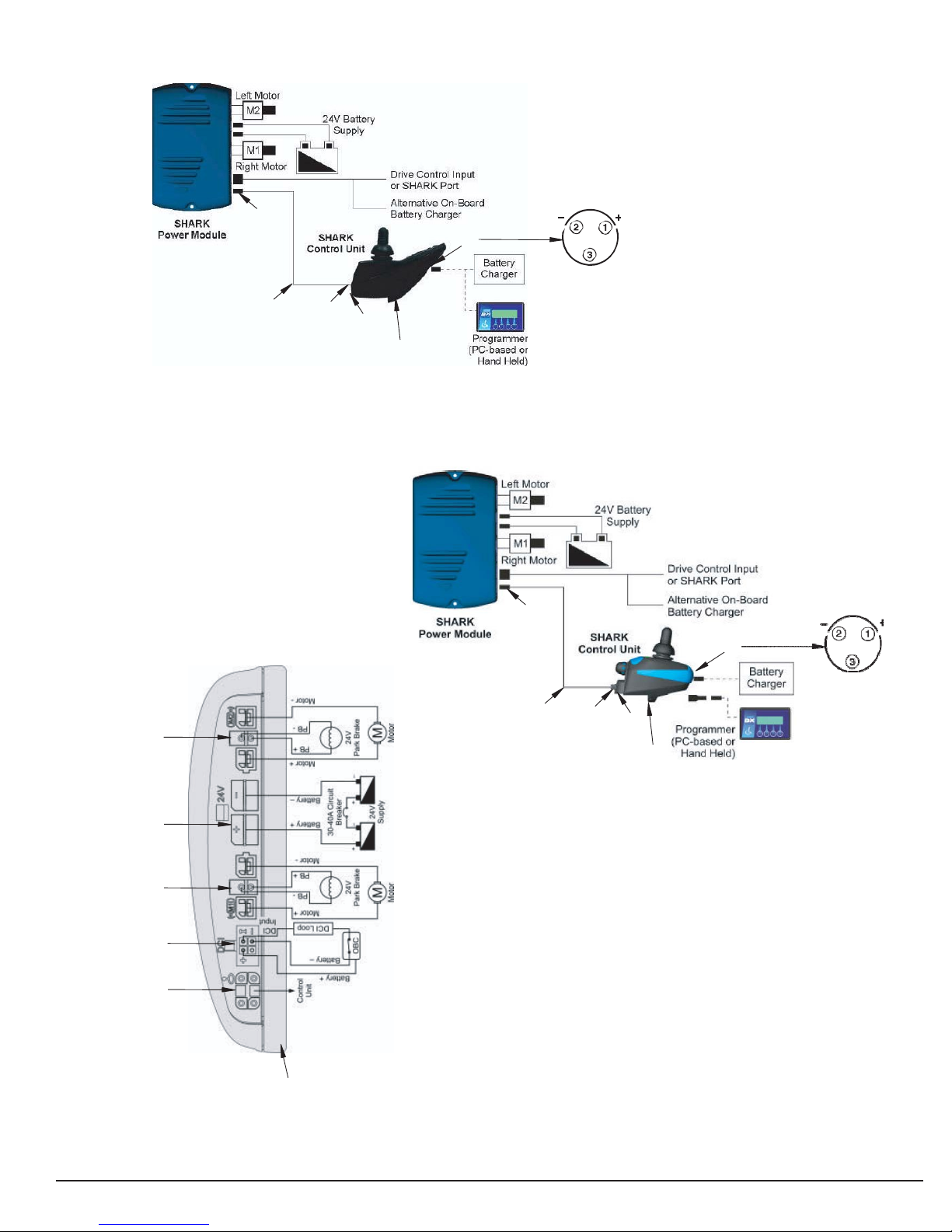
The Liberator control system is made up of the following components (refer to Figures 1 and 2:
• 12V/(35AH or 55AH) Batteries (2) (BAT)
• Battery Harnesses (BH)
• Main Circuit Breaker (CB)
• Battery Charger (BC)
• Power Harness (PH)
• Motors (RMT/LMT)
• Motor Brakes (RMT/LMT)
• Dynamic Shark Power Module (PM)
• Dynamic Shark Joystick Module (JM)
• Joystick Harness (JH)
• Dynamic A-Series Controller (JM)
Component: 12VDC/ (35 or 55AH) Batteries (2)
Location: Connected in series inside the battery box.
Function: Supply 24VDC to the motor and/or accessories (12VDC x 2.)
Connections: Front Battery (BATF) and Rear Battery (BATR).
Failure Signs: Batteries drain quickly. Power chair runs slowly or not at all. Batteries will not charge, but charger is
working properly. Flash Code #2.
Tests: Load test. Fully charge the batteries first. Make sure charging system is working. See Battery Charging Test.
Expected Readings: 12 - 14VDC each when fully charged.
Serviceable: Replace batteries as necessary.

www.solarmobilityinc.com
Component: Motor Brake
Location: End of each motor.
Function: Parking brake for the motor.
Connections: RMB (right brake)/LMB (left brake) connects the brake to the motor harness.
Failure Signs: Power chair will not move or moves sluggishly. No audible click when the scooter stops.
Tests: Test for open. See Flash Codes #5 and #6.
Expected readings: Less than 80 ohms but not shorted.
Serviceable: Replace if open.
Component: Circuit Breaker (CB)
Location: Mounted on the front of the power base.
Function: Protects battery circuit from current overload. When the current draw exceeds the breaker rating, the
circuit breaker will open.
Connections: CB1 and CB2 are the terminals on the circuit breaker. CB3 – CB6 are the terminals on wires that
connect the circuit breaker to the batteries.
Failure Signs: Opens repeatedly. May indicate failed circuit breaker or short in the wiring. May also open if the
motors are overloaded (from excessive weight, short in system, etc.)
Test: Measure the resistance across CB1 and CB2. Also check for continuity across the harnesses, connect the
circuit breaker to the battery (CB3 and CB4 and across CB5 and CB6.)
Expected reading: Less than 10 ohms.
Serviceable: Circuit breaker must be replaced with exact current rating. Replace wires as necessary.
Component: Battery Charger (BC)
Location: Stored inside a pouch on the seatback.
Function: Recharges batteries.
Connections: C1 (connects to the charger port on the front of the joystick module.)
Failure Signs: Charger power LED does not go on. Batteries will not charge.
Tests: Charger tests vary. Some chargers may be tested by measuring positive and negative leads on the charger
connector (C1.) Other charges need to see battery voltage before charging.
Expected reading: Varies with charger. See charger test.
Serviceable: Replace if necessary
Component: Motors (LMT/RMT)
Location: Left and right sides of the power base.
Function: Drives the power chair.
Connections: RMT (right motor) and LMT (left motor)
Failure Signs: Power chair runs slowly or not at all.
Tests: Test for internal resistance in motor. Test motor wires for continuity. See Flash Codes #3 and #4.
Expected readings: Internal resistance is less than 50 ohms but not shorted. (NOTE: Can be as low as 0.2 ohms.)
Serviceable: Replace motor.

www.solarmobilityinc.com
Component: Power Module - Shark Control System (PM)
Location: Rear of the power base.
Function: Monitors the system and displays faults when something in the system is out of range. These faults are
displayed as a series of flashes by the battery meter.
Connections: PM1 (to right motor - RMT), PM2 (to power harness - PH1), PM3 (to left motor - LMT), PM5 (to
joystick harness - JH2)
Failure Signs: Flash Code #8.
Tests: Measure voltage at PM5.
Expected readings: Battery voltage.
Serviceable: Replace as necessary.
Component: Joystick Module (JM)
Location: End of the armrest.
Function: Provides user interface to the power chair. Shows battery charge and status of control system.
Connections: JM1 (to charger)/JM2 (to joystick harness - JH1)
Failure Signs: Flash Codes #6 and #7
Tests: Measure voltage at JM1.
Expected readings: Battery voltage.
Serviceable: Replace as necessary.
Component: Joystick Harness (JH)
Location: End of Joystick Module.
Function: Provides connectivity to the power module.
Connections: JH1 (to joystick module - JM2)/JH2 (to power module - PM5)
Failure Signs: Flash Codes #6 and #7
Tests: Measure continuity.
Expected readings: Less than 10 ohms.
Serviceable: Replace if open
www.solarmobilityinc.com
JH2
JM1
JOYSTICK HARNESS
(#8 FROM PAGE 36)
JH1
JM2
JOYSTICK MODULE
(REMD)
JH2
JM1
PM1
JOYSTICK HARNESS
(#10 FROM PAGE 36)
JH1
JM2
JOYSTICK MODULE
(REMA)
PM2
PM3
PM4
(NOT USED)
PM5
Figure 1. Liberator Electrical System Connector Key (Shark Rem A and Rem D)

www.solarmobilityinc.com
+ COM
MOTOR +
PARK BRAKE -
MOTOR -
COM
-
POWER MODULE PM5
PARK BRAKE +
POWER MODULE CONNECTOR PM2
AND JOYSTICK HARNESS CONNECTORS JH1 POWER MODULE CONNECTORS PM1 AND PM2
COM
+
MOTOR -
PARK BRAKE -
MOTOR +
-
COM
POWER HARNESS CONNECTOR PH1
JOYSTICK HARNESS CONNECOR JH2
AND JOYSTICK MODULE CONNECTOR JM2
PARK BRAKE +
MOTOR CONNECTORS LMT AND RMT
CIRCUIT BREAKER
CB2
CB1
CB5 CB3
CIRCUIT
BREAKER
HARNESS
CIRCUIT -
BREAKER
HARNESS
CB6 CB4
BH3
BH1
BATTERY
HARNESS
BATF +
BH4
BH2
FRONT BATTERY
BATF - BH5
BATR -
BH7
BATR +
PH1
REAR BATTERY
BH8
BATTERY
HARNESS
POWER MODULE
POWER
HARNESS
PH2
PH3
BH6
Figure 2. Liberator Electrical System Connector Key (Shark Rem A and Rem D)
www.solarmobilityinc.com
Scenario 1: Press the on/off button and the LED Array does not light up.
(Shark)
NOTE: Make sure that the batteries are fully-charged and connected properly. Refer to the battery connection diagram
on the battery box lid. If the batteries are not fully charged and connected properly, then voltage measurements may
produce faulty readings. Measure voltage across BATR+ and BATF- to get battery voltage. If the batteries will not
charge, go to “Scenario 2: Batteries will not charge.” Reference figures 1 and 2.
1) Check the circuit breaker.
• Tripped? – Reset it.
• Not tripped? – Go to the next step.
• Tripped but does not reset? – Remove the seat and battery box cover. Go to step 12.
2) Measure voltage across pin 1 (B+) and pin 2 (B-) on the joystick module charger socket (JM1.)
• 0VDC? – Go to the next step.
• 18 – 25VDC (or battery voltage)? – Replace the joystick module.
CAUTION! Prevent damage to the Joystick. Be careful when touching the leads on the charger socket.
Do not touch the other pin (#3) with the multi meter leads.
3) Disconnect the joystick harness (JH1) from the joystick module.
4) Measure voltage across pin 1 and pin 4 on the joystick harness (JH1.)
• 0VDC? – Go to the next step.
• 18 – 25VDC (or battery voltage)? – Replace the joystick module.
5) Remove the seat.
6) Remove the battery box cover.
7) Disconnect the joystick module (JM2) from the power module.
8) Measure voltage across pin 1 and pin 4 on the power module (PM5.)
• 0VDC? – Go to the next step.
• 18 – 25VDC (or battery voltage)? – Replace joystick harness.
9) Disconnect the power harness (PH1) from the power module.
10) Measure voltage across pin 1 and pin 4 on the power harness (PH1.)
• 0VDC? – Go to the next step.
• 18 – 25VDC (or battery voltage)? – Replace the power module.
11) Disconnect the power harness from the front battery (BH8) and the back battery (BH6.)
12) Measure voltage across the front battery harness (BH6) and the back battery harness (BH8.)
• 0VDC? – Go to the next step.
• 18 – 25VDC (or battery voltage)? – Replace the power harness.
13) Measure voltage across BATF- and BATR+.
• 0VDC? – Go to the next step.
• 18 – 25VDC? – Check for continuity across the front battery harness (BH5 and BH6) and across the
back battery harness (BH7 and BH8.) Replace as necessary.
14) Measure Resistance across the terminals on the circuit breaker (CB1 and CB2.)
• Less than 10 ohms? – Go to the next step.
• Open? – Replace the circuit breaker.

www.solarmobilityinc.com
15) Check continuity across the circuit breaker harnesses (CB3 and CB4) and (CB5 and CB6) and across the
battery harnesses (BH1 and BH2) and (BH3 and BH4.) Replace as necessary.
SCENARIO 2: Batteries Will Not Charge (Shark Charging Test)
NOTE: Battery chargers will not charge the batteries unless the battery voltage is 18VDC or above and there is a
closed circuit between the batteries. The circuit breaker completes that circuit. Make sure that the circuit breaker is
reset and the batteries are fully charged. If necessary, use a set of known good batteries. Reference figures 1 and 2.
1) Check the voltage across pin 1 and 2 on the charger connector (Check the charger case for the correct pin
polarity.)
WARNING! Do not touch either of the multi meter probes on the third pin or the connector cover. You may
damage the charger.
• Approximately 24VDC? – Go to the next step.
• Less than 24VDC? – Try another wall outlet or known good charger.
2) Remove the seat and the battery box cover.
3) Make sure that the batteries are connected according to the battery connection diagram on the battery cover
lid. Check the batteries and cables for loose or corroded terminals. Clean and tighten if necessary.
4) Measure voltage across the rear battery positive terminal (BATR+) the front battery negative terminal
(BATF-.) These are the two battery terminals opposite the circuit breaker.
• Less than 18VDC? – Load test and replace batteries as necessary.
• More than 18VDC? – Go to next step.
• 0VDC? – Go to step 9.
5) Unplug the battery harnesses (BH6 and BH8) from the power harness (PH2 and PH3.)
Measure voltage across BH6 and BH8.
• Voltage measured in step 1? – Test the battery harnesses for continuity and replace as
necessary.
• 0VDC? – Go to the next step.
6) Reconnect the battery harness to the power harness. Unplug the power harness PH1 from the power module.
Measure voltage across the positive pin and negative pin on PM5.
• Voltage measured in step 1? – Test the power harness for continuity and replace as
necessary.
• 0VDC? – Go to the next step.
7) Disconnect the joystick harness from the power module. Measure voltage across pin 1 and pin 4 on the
joystick harness (JH2.)
• Same voltage measured in step 1? - Replace the power module.
• 0VDC? – Go to the next step.
8) Disconnect the joystick harness from the joystick. Measure voltage across pin 1 and pin 4 the joystick (JM2.)
• Same voltage measured in step 1? - Replace the joystick harness.
• 0VDC? – Replace the joystick module.

www.solarmobilityinc.com
9) Measure Resistance across the terminals on the circuit breaker (CB1 and CB2.)
• Less than 10 ohms? – Go to the next step.
• Open? – Replace the circuit breaker.
10) Check continuity across the circuit breaker harnesses (CB3 and CB4) and (CB5 and CB6) and across the
battery harnesses (BH1 and BH2) and (BH3 and BH4.) Replace as necessary.
Joystick LED Array DIAGNOSTICS (Shark)
In addition to the battery charge level, the LED Array will display other system information. For example, if the
LED Array flashes five times, then pauses, it indicates that there is a fault in the left motor brake. This is Flash Code
#5. Reference figures 1 and 2.
LED ARRAY “CHASE” LEFT-TO-RIGHT FOLLOWED BY A STEADY DISPLAY
This means that the Shark is in inhibit or charging mode. This feature is designed to keep the power chair from
operating while charging. The steady display after the chase indicates the current state of charge. If there is a charger
connected to the power chair, then disconnect it. Turn off the power and then turn it on again.
FLASH CODE #1 – POSSIBLE STALL TIMEOUT OR USER ERROR
1) Turn off the power.
2) Make sure that the Joystick is in the neutral position.
3) Turn on the power.
4) If the error persists – Call Tech Support.
FLASH CODE #2 – BATTERY FAULT
Charge the batteries. If the batteries will not charge, then go to “Scenario 2. Batteries Will Not Charge.”
If after charging the batteries, the code does not go away, then measure voltage across pin 1 and pin 2 on JM1.
• Approximately 24VDC (or battery voltage)? – Replace the power module.
FLASH CODE #3 LEFT MOTOR FAULT
1) Remove the seat.
2) Remove the battery box lid.
3) Disconnect the left motor (LMT) from the power module.
4) Measure resistance across pin 1 and pin 2 on LMT.
• 50 ohms but not shorted? (NOTE: Can be as low as 0.2 ohms.) – Replace the power module (PM.)
• Out of that range? – Go to the next step.
5) Remove the brushes from the left motor and inspect them.
• Worn below 0.25 in. or physically damaged? – Replace the brushes.
• Not worn below 0.25 in. or physically damaged? - Replace the left motor.

www.solarmobilityinc.com
FLASH CODE #4 RIGHT MOTOR FAULT
1) Remove the seat.
2) Remove the battery box lid.
3) Disconnect the right motor (RMT) from the power module.
4) Measure resistance across pin 1 and pin 2 on RMT.
• 50 ohms but not shorted? (NOTE: Can be as low as 0.2 ohms.) – Replace the power module.
• Out of that range? – Go to the next step.
5) Remove the brushes from the right motor and inspect them.
• Worn below 0.25 in. or physically damaged? – Replace the brushes.
• Not worn below 0.25 in. or physically damaged? - Replace the right motor.
FLASH CODE #5 LEFT PARK BRAKE
1) Remove the seat.
2) Remove the battery box lid.
3) Disconnect the left motor (LMT) from the power module.
4) Measure resistance across pin 3 and pin 4 on LMT.
• 80 ohms or less but not shorted? – Replace the power module.
• Shorted or open? – Replace the motor brake.
FLASH CODE #6 RIGHT PARK BRAKE FAULT
1) Remove the seat.
2) Remove the battery box lid.
3) Disconnect the right motor (RMT) from the power module.
4) Measure resistance across pin 3 and pin 4 on RMT.
• 80 ohms or less but not shorted? – Replace the power module (PM.)
• Shorted or open? – Replace the motor brake.
FLASH CODE #7 - SHARK CONTROLLER MODULE FAULT
FLASH CODE #8 - SHARK POWER MODULE FAULT FLASH
CODE #9 - SHARK COMMUNICATIONS FAULT FLASH
CODE #10 - UNKNOWN FAULT
1) Remove the seat.
2) Remove the battery cover.
3) Unplug the joystick harness (JH1) from the joystick module and (JH2) from the power module. Measure
resistance across the following pins on the joystick harness:
• Pin 2 on JH1 and pin 2 on JH2.
• Pin 3 on JH1 and pin 3 on JH2.
Open? — Replace the joystick harness.
Less than 10 ohms? — Go to the next step.
4) Check the joystick harness (JH1/JH2), the joystick module (JM2), and the power module (PM4) connectors
for damage or corrosion. Clean with electrical contact cleaner.
• Damage? – Replace damaged parts.
• No damage? — Replace the power module or joystick module with a known good unit.

www.solarmobilityinc.com
PARK BRAKE -
MOTOR +
MOTOR -
PARK BRAKE +
POWER MODULE CONNECTORS JM3 and JM4
CIRCUIT BREAKER HARNESS CONNECTOR CB5
PARK BRAKE -
MOTOR -
PARK BRAKE +
MOTOR CONNECTORS LMT1 AND RMT2
JM4
JM1
RMT1
JM2
JM3
LMT1
CB4
CB5
CB1
BATR1
CB3
CB2
BATF-
BATR-
BATF1
BATF+
BATR+
Figure 3. Liberator Electrical System Connector Key (A Series)

www.solarmobilityinc.com
Scenario 1: Press the on/off button and the LED Array does not light up.
(A Series)
NOTE: Make sure that the batteries are fully-charged and connected properly. Refer to the battery connection
diagram on the battery box lid. If the batteries are not fully charged and connected properly, then voltage
measurements may produce faulty readings. Measure voltage across BATF+ and BATR- to get battery voltage.
If the batteries will not charge, go to "Scenario 2: Batteries will not charge." Reference figures 1 and 3.
1) Check the circuit breaker.
• Tripped? - Reset it.
• Not tripped? - Go to the next step.
• Tripped but does not reset? - Remove the seat and battery box cover. Go to step 11.
2) Measure voltage across pin 1 (B+) and pin 2 (B-) on the joystick module charger socket (JM1.)
• 0VDC? - Go to the next step.
• 18 - 25VDC (or battery voltage)? - Replace the joystick module.
CAUTION! Prevent damage to the Joystick. Be careful when touching the leads on the charger socket.
Do not touch the other pin (#3) with the multi meter leads.
3) Remove the joystick from the armrest.
4) Remove the Seat.
5) Remove the battery cover.
6) Disconnect the joystick harness (JH1) from the circuit breaker harness (CB5.)
7) Measure voltage across pins 1 and pin 2 on CB5.
• 0VDC? - Go to the next step.
• 18 - 25VDC (or battery voltage)? - Replace the joystick module.
8) Unplug the battery harnesses (BATF1 and BATR1) from the circuit breaker harness (CB3 and CB4.)
Measure voltage across both battery harnesses. Add the battery voltages.
• Is it the total of both batteries the same as measured in step 7? - Go to the next step.
• 0VDC on either harness? - Test the battery harnesses for continuity and replace as necessary.
9) Measure Resistance across the terminals on the circuit breaker (CB1 and CB2.)
• Less than 10 ohms? - Go to the next step.
• Open? - Replace the circuit breaker.
10) Check continuity across the circuit breaker harnesses (CB1 and CB4) and (CB2 and CB3.) Replace as
necessary.

www.solarmobilityinc.com
SCENARIO 2: Batteries Will Not Charge (A Series)
NOTE: Battery chargers will not charge the batteries unless the battery voltage is 18VDC or above and there is a
closed circuit between the batteries. The circuit breaker completes that circuit. Make sure that the circuit breaker is
reset and the batteries are fully charged. If necessary, use a set of known good batteries. Reference figures 1 and 3.
1) Check the voltage across pin 1 and 2 on the charger connector (Check the charger case for the correct pin
polarity.)
WARNING! Do not touch either of the multimeter probes on the third pin or the connector cover. You may
damage the charger.
• Approximately 24VDC? - Go to the next step.
• Less than 24VDC? - Try another wall outlet or known good charger.
2) Remove the seat and the battery box cover.
3) Make sure that the batteries are connected according to the battery connection diagram on the battery cover
lid. Check the batteries and cables for loose or corroded terminals. Clean and tighten if necessary.
4) Measure voltage across the rear battery positive terminal (BATR+) the front battery negative terminal
(BATF-.) These are the two battery terminals opposite the circuit breaker.
• Less than 18VDC? - Load test and replace batteries as necessary.
• More than 18VDC? - Go to next step.
• 0VDC? - Go to step 9.
5) Unplug the battery harnesses (BATF1 and BATR1) from the circuit breaker harness (CB3 and CB4.)
Measure voltage across both battery harnesses. Add the battery voltages.
• Is it total of both batteries the same as measured in step 4? - Go to the next step.
• 0VDC on either harness? - Test the battery harnesses for continuity and replace as necessary.
6) Plug the battery harnesses back into the circuit breaker harness.
7) Unplug the joystick harness from the circuit breaker harness.
8) Measure the voltage across the two pins on the circuit breaker harness (CB5.)
• Voltage measured in step 1? - Replace the joystick module.
• 0VDC? - Go to the next step.
9) Measure Resistance across the terminals on the circuit breaker (CB1 and CB2.)
• Less than 10 ohms? - Go to the next step.
• Open? - Replace the circuit breaker.
10) Check continuity across the circuit breaker harnesses (CB1 and CB4) and (CB2 and CB3.) Replace as
necessary.

www.solarmobilityinc.com
Joystick LED Array DIAGNOSTICS (A Series)
In addition to the battery charge level, the LED Array will display other system information. For example, if the
LED Array flashes five times, then pauses, it indicates that there is a fault in the left motor brake. This is Flash Code
#5. Reference figure 3.
LED ARRAY "CHASE" LEFT-TO-RIGHT FOLLOWED BY A STEADY DISPLAY
This means that the A Series is in inhibit or charging mode. This feature is designed to keep the power chair
from operating while charging. The steady display after the chase indicates the current state of charge. If there is a
charger connected to the power chair, then disconnect it. Turn off the power and then turn it on again.
FLASH CODE #1 - POSSIBLE STALL TIMEOUT OR USER ERROR
1) Turn off the power.
2) Make sure that the Joystick is in the neutral position.
3) Turn on the power.
• If the error persists - Call Tech Support.
FLASH CODE #2 - BATTERY FAULT
Charge the batteries. If the batteries will not charge, then go to "Scenario 2. Batteries Will Not Charge."
• If after charging the batteries, the code does not go away, then measure voltage across pin 1 and pin 2 on
JM1.
• Approximately 24VDC (or battery voltage)? - Replace the power module.
FLASH CODE #3 LEFT MOTOR FAULT
1) Remove the seat.
2) Remove the battery box lid.
3) Disconnect the left motor (LMT1) from the joystick module.
4) Measure resistance across pin 1 and pin 2 on LMT1.
• 50 ohms but not shorted? (NOTE: Can be as low as 0.2 ohms.) - Replace the joystick module.
• Out of that range? - Go to the next step.
5) Remove the brushes from the left motor and inspect them.
6) Worn below 0.25 in. or physically damaged? - Replace the brushes.
7) Not worn below 0.25 in. or physically damaged? - Replace the left motor.
FLASH CODE #4 RIGHT MOTOR FAULT
1) Remove the seat.
2) Remove the battery box lid.
3) Disconnect the right motor (RMT1) from the joystick module.
4) Measure resistance across pin 1 and pin 2 on RMT1.
• 50 ohms but not shorted? (NOTE: Can be as low as 0.2 ohms.) - Replace the joystick module.
• Out of that range? - Go to the next step.
5) Remove the brushes from the right motor and inspect them.
6) Worn below 0.25 in. or physically damaged? - Replace the brushes.
7) Not worn below 0.25 in. or physically damaged? - Replace the right motor.

www.solarmobilityinc.com
FLASH CODE #5 LEFT PARK BRAKE
1) Remove the seat.
2) Remove the battery box lid.
3) Disconnect the left motor (LMT1) from the joystick module.
4) Measure resistance across pin 3 and pin 4 on LMT1.
• 80 ohms or less but not shorted? - Replace the joystick module.
• Open or shorted? - Replace the motor brake.
FLASH CODE #6 RIGHT PARK BRAKE FAULT
1) Remove the seat.
2) Remove the battery box lid.
3) Disconnect the right motor (RMT1) from the joystick module.
4) Measure resistance across pin 3 and pin 4 on RMT1.
• 80 ohms or less but not shorted? - Replace the joystick module.
• Open or shorted? - Replace the motor brake.
FLASH CODE #7 - INTERNAL USER FAULT
FLASH CODE #8 - CONTROLLER FAULT
FLASH CODE #9 - INTERNAL COMMUNICATIONS FAULT
FLASH CODE #10 - UNKNOWN FAULT
1) Remove the seat.
2) Remove the battery cover.
3) Check the joystick harness connector and the circuit breaker harness connector for damage or corrosion.
Clean with electrical contact cleaner.
• Damage? - Replace damaged parts.
• No damage? - Replace the joystick module with a known good unit.
www.solarmobilityinc.com
REPLACEMENT INSTRUCTIONS
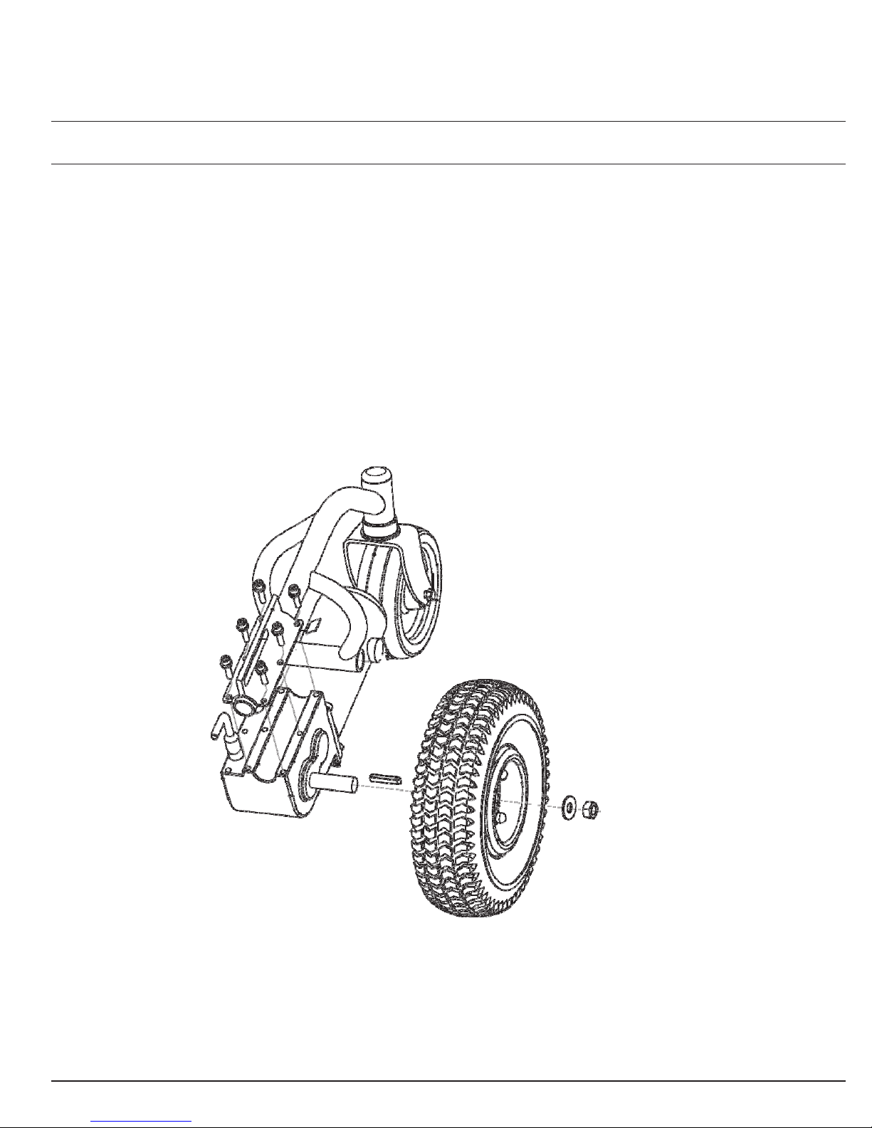
DRIVE WHEEL
To replace the drive wheel:
1) Turn off power to the joystick module.
2) Place the power chair in drive mode.
3) Place a support under the frame so that the drive wheel is off of the ground.
4) Remove the drive wheel. Make sure to retain the axle key. See figure 4.
5) Install the new drive wheel. Make sure that the axle key is installed correctly in the axle slot.
6) Remove the frame support.
7) Power on and test the power chair.
AXLE KEY
Figure 4. Liberator Drive Wheel Assembly
www.solarmobilityinc.com
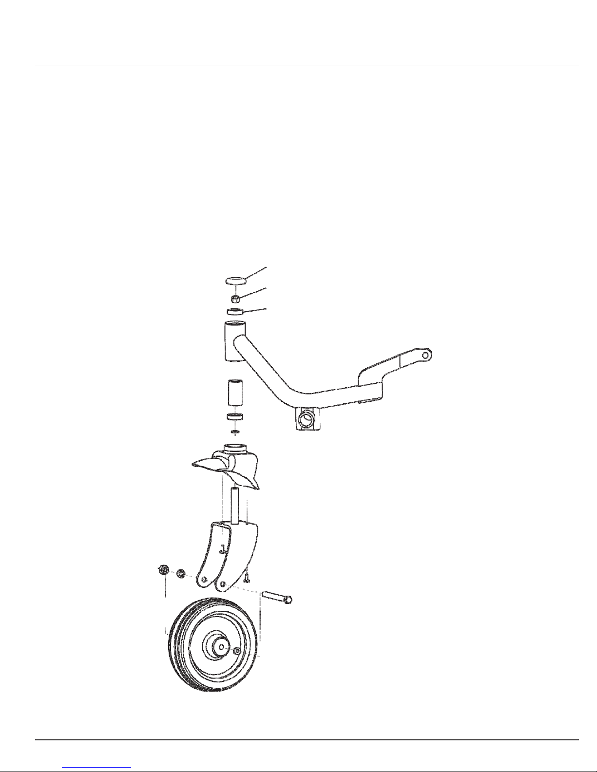
FRONT CASTER
NOTE: Refer to the parts diagram for the current part number.
To replace the drive:
1) Turn off power to the joystick module.
2) Place the power chair in drive mode.
3) Place a support under the frame so that the caster wheel is off of the ground.
4) Remove the cap from caster arm. See figure 4.
5) Remove the nut that fastens the caster wheel to the caster arm. See figure 5. Make sure you retain the
washer.
6) Install the new caster assembly.
7) Remove the frame support.
8) Power on and test the power chair.
CAP
NUT
WASHER
Figure 5. Front Caster Assembly
www.solarmobilityinc.com
DRIVETRAIN (MOTOR AND GEARBOX)
NOTE: Refer to the current parts diagram for the current part number.
To replace the motor:
1) Turn off power to the joystick
module.
2) Place the power chair in drive mode.
3) Disconnect the joystick harness from
the joystick module.
4) Remove the seat.
5) Remove the seat receiver assemblies.
6) Remove the battery box cover.
7) Disconnect and remove the batteries.
8) Disconnect the motor (either left or
right) from the power module.
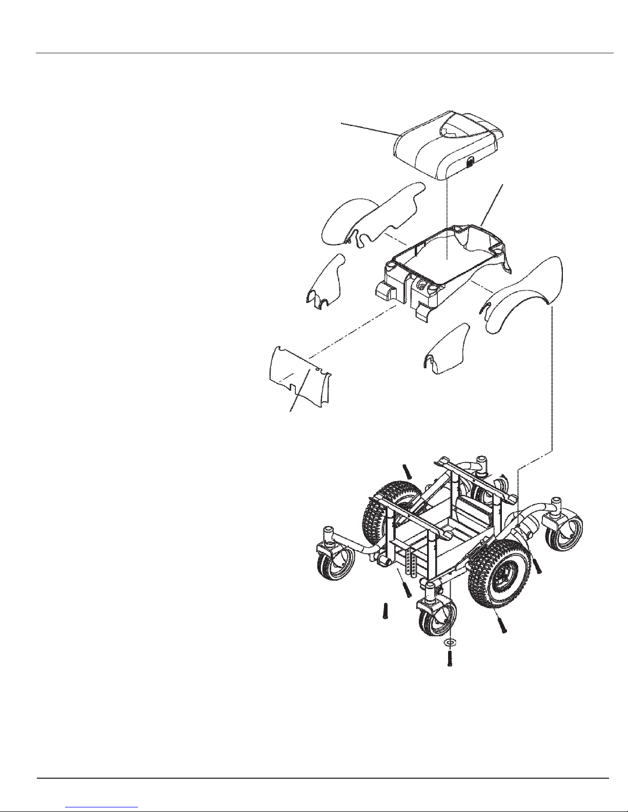
9) Remove the shroud (either right or
left) from the frame. See figure 6.
10) Disconnect the circuit breaker from
the frame.
11) Unfasten the battery shroud from the
frame. See figure 6.
12) Unfasten the drivetrain from the
frame. See figure 7.
13) Lift up the battery shroud enough to
pull the motor harness through the
frame.
14) Install the new drivetrain onto the
frame.
15) Connect the drivetrain to the power
module.
16) Reinstall the battery shroud to the
frame.
17) Reinstall the circuit breaker.
18) Reinstall the batteries.
16) Reinstall the battery box cover.
17) Reinstall the seat receiver assemblies.
18) Reinstall the seat.
19) Connect the joystick module to the
joystick harness.
20) Power on and test the power chair.
BATTERY BOX
COVER
FRONT
SHROUD
BATTERY
SHROUD
NOTE: MODELS AFTER S/N CW07I0001 USE SNAP-ON SHROUDS
Figure 6. Liberator Shroud Assembly
Table of contents


