SolarEdge SEHAZB-SCKT-MTR-XX User manual

Plug-In Socket with Meter Installation Guide
Overview
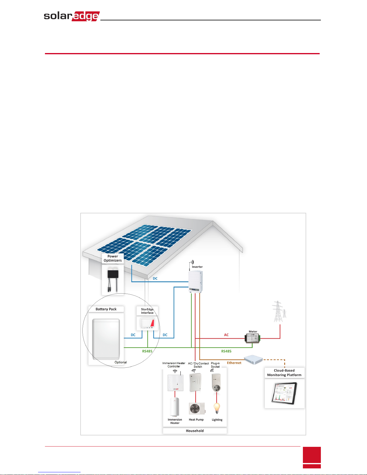
The SolarEdge Smart Energy Management solutions allow increasing the self-consumption of a site. One
method used for this purpose is controlling the usage (consumption) of loads using Device Control
products.
The SolarEdge Device Control units divert power to an appliance (load) according to pre-configured
schedules, using the following modes:
Refer to Figure 2 for examples of the device modes of operation.
You can re-configure the schedules at any time and manually switch appliances on and off.
You can configure the Device Control products locally through the SolarEdge inverter or remotely, via
the SolarEdge monitoring portal.
The SolarEdge Plug-In Socket (referred to as "the device") is a ZigBee wireless AC switch with a built-in
energy and power-consumption meter that provides power measurements up to 2.5kW. Based on these
measurements and on the system configuration it switches the loads on and off.
Figure 1: SolarEdge system with Device Control products
Plug-In Socket with Meter Installation Guide
SolarEdge-Plug-in socket Installation Guide
1
Schedule - TThe device turns on and off at times set by the user for the user’s convenience, regardless of
available PV power.w
Smart Save - The device (typically a boiler or water pump) is controlled automatically to maximize self-
consumption. Grid power is used only if PV power is insufficient to meet the user’s “ready by” time. For
example, to heat water for 2 hours and have hot water by 18:00, set Total Time to 2 hours and Ready by to
The boiler may work before 16:00 if there is available PV power, but in any case you are guaranteed to .18:00
have hot water by 18:00.w
l
l
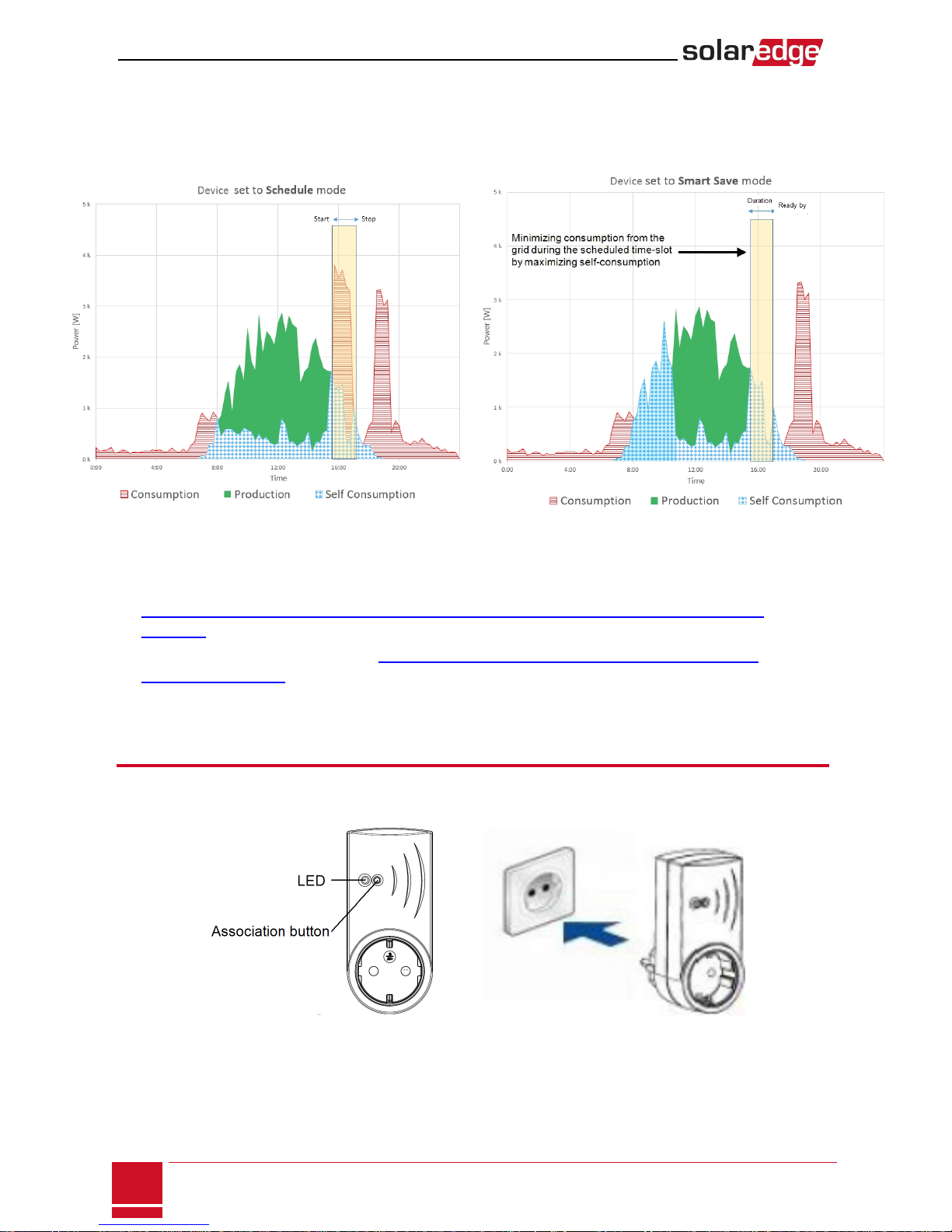
The following figure illustrates a typical example of device operation with Smart Save and Schedule
modes. Note that in Smart Save mode, the consumption is reduced by taking advantage of excess PV
earlier in the day.
Figure 2: Examples of device operation
To enable the Plug-in socket functionality, the following supporting devices must be installed:
lDevice Control ZigBee Module, installed inside the inverter. For physical installation refer to
http://www.solaredge.com/sites/default/files/se-device-control-zigbee-module-installation-
guide.pdf.
lSolarEdge Modbus Meter. Refer to http://www.solaredge.com/files/pdfs/solaredge-meter-
installation-guide.pdf
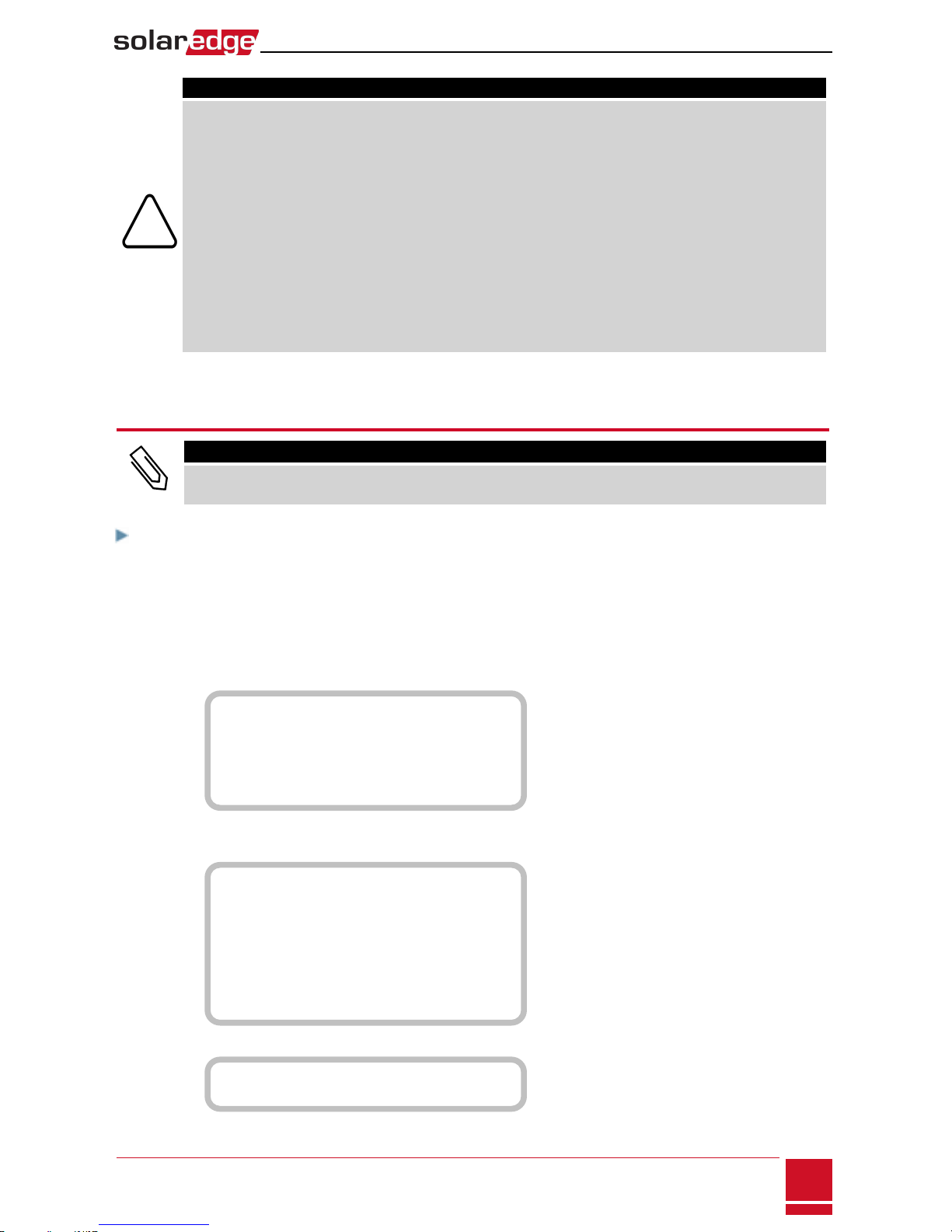
Installation
Figure 3: The Plug-in Socket
SolarEdge Plug-in socket Installation Guide
2
Installation
CAUTION!
lThis product must be operated under the specified operating specifications, as described in
the latest technical specification datasheet.
lConfigure the product so that the load connected is not switched on or off more
frequently than specified by the load manufacturer.
lDo not connect loads that require a continuous current supply (e.g. fridge, freezer).
lDo not use the product if it is damaged or malfunctioning.
lNever connect loads that can cause injuries or fire if they are switched on unintentionally
(e.g. an iron).
lDo not let the product come into contact with water or other liquids.
lThe enclosed documentation is an integral part of this product. Keep the documentation
in a convenient place for future reference and observe all instructions contained therein.
Plug the device into a wall socket , at a maximum distance of 50 m from the inverter.
Configuration
NOTE
Verify that the inverter is connected to the monitoring portal (refer to the Inverter Installation Guide for
details on setting up communication).
To associate the device with the ZigBee network:
1. Enter the inverter Setup mode as described in the Inverter Installation Guide.
2. Select Communication èZigBee Conf..
3. Select:
lDevice TypeèHA (Home Automation)
lProtocol èHAM (Home Automation)
D e v i c e T y p e < H A >
Protocol<HAM>
P A N I D
Scan Channel
L o a d Z B D e f a u l t s
When HA Device Type is selected, a Device Manager menu item will appear in the main configuration
menu:
C o u n t r y < I t a l y >
L a n g u a g e < E n g >
Communication
P o w e r C o n t r o l
Display
Maintenance
Information
4. From the main menu select Device Manager. The Device Manager screen is displayed:
A d d D e v i c e s < 0 >
5. Select Add Devices to start the device association with the inverter.
Plug-In Socket with Meter Installation Guide
SolarEdge-Plug-in socket Installation Guide
3

6. Press the association button on the Plug-in socket (see Figure 1).
The Device Manager screen should display a new line for each discovered device, including the 3 last
digits of its serial number, operating mode and operating state. Discovery time may take up to 3
minutes. You can press the inverter LCDlight button or the internal ESC button to exit the discovery
process when all devices are discovered.
A d d D e v i c e s < 3 >
R e g x x x < A u t o , O F F >
S E - S W x x x < M a n , O F F >
S E - S - P L G x x x < M a n , O F F >
R e m o v e A l l
Device types:
lREG - Immersion heater controller
lSE-SW - Dry contact switch
lSE-S-PLG - Plug-in socket
lSE-S-SW - AC switch with meter
7. Select the device. The device configuration screen is displayed:
Mode<Manual>
S t a t e < O F F >
D e v i c e I n f o
R e m o v e D e v i c e
For the following device configuration steps, you can use either the inverter LCDbuttonsor the
monitoring portal. The steps herein show configuration using the inverter LCD.
8. Select Mode. The mode configuration screen is displayed:
M a n u a l
A u t o
lManual - turns the device to ONor OFF, as described below
lAuto - allows setting two types of schedules for device control, as described in the next sections:
oSmart Save - set the device operation requirements (ready-by and duration values). This mode
is useful for maximizing self-consumption using excess PVpower: the device operates
autonomously based on configured settings.
oSchedule - set the device start and stop times regardless of available excess PVpower.
To set Manual mode:
1. Select Mode èManual
2. Select ON or OFFto turn the device on or off.
To set Auto mode:
1. Select Auto. The following screen is displayed, showing options for setting the device parameters:
M o d e < A u t o >
A d d S c h e d u l e
D e v i c e P r o p e r t i e s
D e v i c e I n f o
R e m o v e D e v i c e
SolarEdge Plug-in socket Installation Guide
4
Configuration

2. Select Device Properties and set the following properties:
L o a d R a t i n g < x . x K W >
E x p o r t T H < x x x x W >
I m p o r t T H < x x x x W >
M i n O n T i m e < x x x >
lLoad Rating - the appliance rated power (in kW)
lExport TH (threshold) - optional; the minimum power (in W) above which the excess PV power
will be diverted to the appliance. This value can be lower than the load rating. The default value is
5% above the Load Rating.
lImport TH (threshold) - optional; the maximum power (in W) purchased from the grid and
diverted to the appliance. The default value is 5% of the Load Rating.
NOTE
If changing the Export TH and Import TH default values, make sure they sum up to a
value that equals or greater than the appliance Load Rating value. Otherwise, the
device will turn off when there is insufficient power to divert to the appliance.
lMin ONTime - (optional); the minimum duration (in minutes) the appliance should remain ON
once switched on, even when no excess PVpower is available. The default value is 1 minute.e
3. Select Add Schedule. The following screen is displayed, showing schedule setting options. You can
configure up to four different schedules.
S m a r t S a v e
S c h e d u l e
Disable
D e l e t e
Use Disable to deactivate a schedule or Delete to remove it.
Plug-In Socket with Meter Installation Guide
SolarEdge-Plug-in socket Installation Guide
5

4. Select and set one of the scheduling options:
lSmart Save:
S e t < S m a r t >
R e a d y b y < 0 0 : 0 0 >
D u r a t i o n < 0 0 >
M a x D u r a t i o n < 0 0 >
Week Days<1234567>
oReady by - requested energy must be diverted to the load by this time (default: 00:00;
format:hours:minutes).
oDuration - minimum accumulated time the load must remain on (in minutes; default: 00).
oMax Duration - maximum accumulated time the load can be on throughout the day (in
minutes; default: 00).
If the value of Max Duration is longer than the value of Duration, the device will use up only
excess PV energy in the difference time. For example, if Max Duration = T1 and Duration =
T2, during (T1-T2) only excess PV power will be used.
oWeek Days (optional) - days to repeat the settings (default: every day).
lSchedule:
S e t < S c h e d u l e >
S t a r t T i m e < 0 0 : 0 0 >
S t o p T i m e < 0 0 : 0 0 >
Week Days <1234567>
oStart/Stop Time - the time of day by which the Plug-in socket must start/complete its
task of delivering energy to the load (default: 00:00; format:hours:minutes). If these
values are not set, only the excess PV power is used.
oWeek Days (optional) - days to repeat the settings (default: every day).
NOTE
In Auto mode , if you configure overlapping time-frames between Schedule and Smart Save
options, Schedule mode takes precedence over the Smart Save mode.
Once the installation process is complete you can re-configure the device operation mode and schedules.
To Do this
Manually turn the load on or off Select the device from the Device Manager screen. Select
Mode èManual and set the device to either ON or OFF.
Modify the schedule configuration
Select the device from the Device Manager screen. Select
Mode èAuto and set the parameters of any menu: Smart
Save/Schedule.
Disable or delete a schedule Select Disable or Delete from the Schedule screen.
Disconnect the device(s) from the network Select Remove Device or Remove All from the device
screen.
SolarEdge Plug-in socket Installation Guide
6
Configuration

Verifying the Connection
1. Check the status screens:
lHA devices status, showing the device name and state: ON, OFF, or an asterisk (*), which indicates
no communication with the device:
HA Devices State:
S E - S - P L G 0 1 1 < O N >
lCommunication status, showing the number of communicating HAdevices (under Prot) and the
number of detected devices (under ##):
w w w w w DevProt ##
R S 4 8 5 - 1 < - - - > < - - > < - >
Z i g B e e < H A > < 1 > < 1 >
2. To check the device details, from the device configuration screen, select Device Info. The following
screen is displayed:
MAC: xxxxxxxxxxx
L a s t s e e n : < D D : H H >
MFG: SolarEdge
M o d e l : S E - S - P L G
P o w e r [ W ] : 0
lMAC: the full MACaddress of the device
lLast seen: The date and time when the device communicated with the inverter
lMFG: The device manufacturer
lModel: The device model type
lPower [W]: The energy delivered to the load
LEDIndications
The device has a bi-color LED (red/ green) that provides information about its operation status:
LEDfunction Indication
Solid green (2 seconds), flashing green (2
seconds) Reset
Flashing red No ZigBee association with the inverter
Flashing green ZigBee association in process
Solid green ZigBee association completed and the relay is closed
Solid red ZigBee association completed and the relay is open
Plug-In Socket with Meter Installation Guide
SolarEdge-Plug-in socket Installation Guide
7
Button Functionality
The following table describes the device button functions depending on the network association state:
Network state Pressing duration Result
No ZigBee association with
the inverter Any Attempt to associate with the network
ZigBee associated with the
inverter
Up to 3 seconds (short
press)
Manually toggle ON/OFFstate (manual mode). To
return to Auto/Scheduled states, configure the
device using the mobile application or monitoring
portal.
More than 10 seconds
(long press)
Disconnect from the network (the LED turns red and
the device resets).
3 - 10 seconds
Start a discovery search for nearby devices. The
discovery may take up to 3 minutes during which the
device is not functional. Not required for normal
operation.
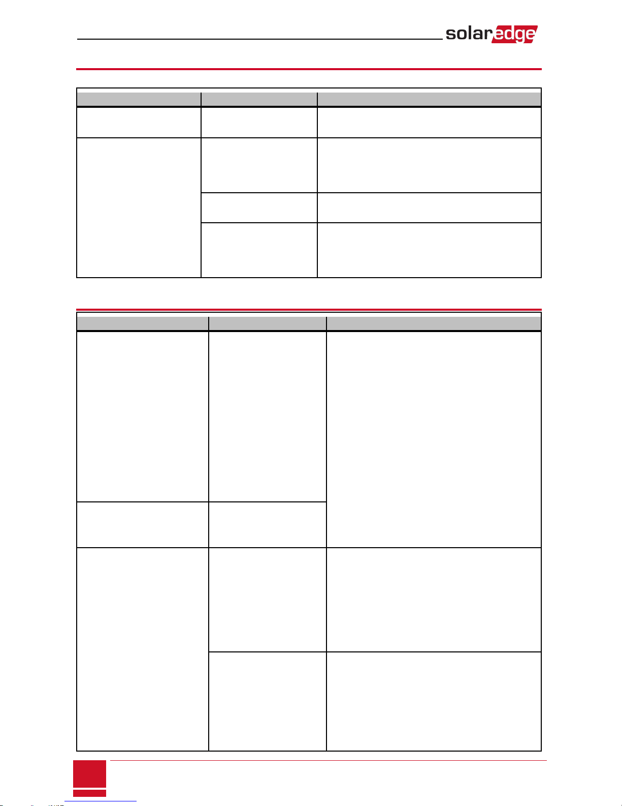
Troubleshooting
Symptom / Error Possible cause Troubleshooting
oAn asterisk (*) is displayed
next to the Device type in
the device manager
screen indicating that the
device is not
communicating.
oIn the Communication
status screen, the number
of detected devices does
not match the number of
communicating devices.
oThe device is powered on
but the green LED is OFF
The device
is not associated with the
inverter
Try to solve using these options. If problem is not
solved, proceed with the next option:
oTurn the device OFF and ON. Recheck
communication.
oReset the device by pressing the button for
more than 10 seconds and then repeat the
association process. Reconfiguration is not
required.
oFrom the Device Manager screen select
Remove Device and repeat the discovery
process. Reconfiguration is required in this
case.
oContact SolarEdge support.
The device is powered on and
the green LED is ON
The device is Associated
with the inverter but is not
communicating.
All the devices are not
communicating
No ZigBee error is
displayed on the inverter
LCD - The inverter has not
detected the installed
ZigBee module.
oTurn OFFthe AC to the inverter.
oCheck that the ZigBee module is inserted
correctly inside the inverter.
oTurn ON the AC to the inverter.
Network problems
Try to solve using these options. If problem is not
solved, proceed with the next option:
oCheck the ZigBee status screen:Verify that
PAN has been established and Channel is not
0:
SolarEdge Plug-in socket Installation Guide
8
Button Functionality
Symptom / Error Possible cause
oTurn the inverter OFF and ON (power cycle).
oReset all the devices using the association
button and begin the discovery process again
for all devices.
oFrom the Device Manager screen select
Remove All and repeat the discovery process
for all the devices.
oContact SolarEdge support.
Error message Device limit
reached. Remove devices
from the device list is
displayed in the LCD.
You are attempting to
associate more than 10
devices to the load
managemnt network.
Remove an unused device from the device list
before attempting to add another device.
Plug-In Socket with Meter Installation Guide
SolarEdge-Plug-in socket Installation Guide
9
PAN:XXXXX
CH:XX/XXXXRSSI:<L>
M I D : X X X X X X
Troubleshooting

Specifications
ELECTRICAL SERVICE SEHAZB-SCKT-MTR-XX1
Operating Voltage Range - Line to
Neutral 90 - 250 Vac
AC Frequency 50/60 Hz
Maximum Active Power
Measurement
3kW
Maximum Load Current 13 A
COMMUNICATION
Supported Communication Protocol ZigBee Home Automation
Nominal Transmit Power 3 dBm
Operating Frequency Range 2.4 - 2.5 GHz
Outdoor (LOS) Range 100 m
Indoor Range250 m
STANDARD COMPLIANCE
Radio ETSI EN 300 328 V 1.8.1, ETSI EN 301 489-1, ETSI EN 301
489-17
Safety EN 60335-1, EN 60335-2-30, EN 50371
Immunity EN 55014-2
Emissions EN 55014-1, EN 61000-3-2, EN 61000-3-3
INSTALLATION SPECIFICATIONS
Operating Temperature Range 0 to +50 °C
Protection Rating IP30
Dimensions (H x W x D) 110 x 50 x 40 mm
1Multiple plug types for various sockets: XX = GB, DE, FR, IT
2Approximate values. May differ depending on specific installation conditions.
SolarEdge Plug-in socket Installation Guide
10
Specifications

Table of contents
Other SolarEdge Accessories manuals


