SolarEdge Smart Energy Series User manual

Installation Guide
Smart Energy Socket
Version 1.2

Disclaimers
Important Notice
Copyright © SolarEdge Inc. All rights reserved.
No part of this document may be reproduced, stored in a retrieval system or
transmitted, in any form or by any means, electronic, mechanical, photographic,
magnetic or otherwise, without the prior written permission of SolarEdge Inc.
The material furnished in this document is believed to be accurate and reliable.
However, SolarEdge assumes no responsibility for the use of this material. SolarEdge
reserves the right to make changes to the material at any time and without notice. You
may refer to the SolarEdge web site (www.solaredge.com) for the most updated version.
All company and brand products and service names are trademarks or registered
trademarks of their respective holders.
Patent marking notice: see http://www.solaredge.com/patent
The general terms and conditions of delivery of SolarEdge shall apply.
The content of these documents is continually reviewed and amended, where
necessary. However, discrepancies cannot be excluded. No guarantee is made for the
completeness of these documents.
The images contained in this document are for illustrative purposes only and may vary
depending on product models.
Emission Compliance
This equipment has been tested and found to comply with the limits applied by the
local regulations.
These limits are designed to provide reasonable protection against harmful interference
in a residential installation. This equipment generates, uses and can radiate radio
frequency energy and, if not installed and used in accordance with the instructions,
may cause harmful interference to radio communications. However, there is no
guarantee that interference will not occur in a particular installation. If this equipment
does cause harmful interference to radio or television reception, which can be
determined by turning the equipment off and on, you are encouraged to try to correct
the interference by one or more of the following measures:
Reorient or relocate the receiving antenna.
Increase the separation between the equipment and the receiver.
Smart Energy Socket
1 Disclaimers

Connect the equipment into an outlet on a circuit different from that to which the
receiver is connected.
Consult the dealer or an experienced radio/TV technician for help.
Changes or modifications not expressly approved by the party responsible for
compliance may void the user’s authority to operate the equipment.
Disclaimers 2
Smart Energy Socket
Contents
Disclaimers 1
Important Notice 1
Emission Compliance 1
HANDLING AND SAFETY INSTRUCTIONS 4
Safety Symbols Information 4
Revision History 5
Overview 6
Installation 9
Configuration 11
Configuration with Inverters with LCDScreen 11
Configuration with Inverters with SetApp 16
Modifying the Device Operation Mode and Schedules 19
Verifying the Connection 20
LEDIndications 20
Button Functionality 22
Troubleshooting 23
Specifications 25
3
Smart Energy Socket

HANDLING AND SAFETY INSTRUCTIONS
During installation, testing and inspection, adherence to all the handling and safety
instructions is mandatory. Failure to do so may result in injury or loss of life and
damage to the equipment.
Safety Symbols Information
The following safety symbols are used in this document. Familiarize yourself with the
symbols and their meaning before installing or operating the system.
WARNING!
Denotes a hazard. It calls attention to a procedure that, if not correctly
performed or adhered to, could result in injury or loss of life. Do not proceed
beyond a warning note until the indicated conditions are fully understood and
met.
CAUTION!
Denotes a hazard. It calls attention to a procedure that, if not correctly
performed or adhered to, could result in damage or destruction of the
product. Do not proceed beyond a caution sign until the indicated conditions
are fully understood and met.
NOTE
Denotes additional information about the current subject.
IMPORTANTSAFETYFEATURE
Denotes information about safety issues.
Disposal requirements under the Waste Electrical and Electronic Equipment (WEEE)
regulations:
NOTE
Discard this product according to local regulations or send it back to SolarEdge.
Smart Energy Socket
4 HANDLING AND SAFETY INSTRUCTIONS

Revision History
Version 1.2 (August 2019)
Addition of SetApp configuration
Version 1.1 (May 2018)
Terminology and product name updates
Revision History 5
Smart Energy Socket

Overview
The SolarEdge Smart Energy solutions allow increasing the self-consumption of a site.
One method used for this purpose is controlling the usage (consumption) of loads
using Smart Energy products.
The Smart Energy devices divert power to an appliance (load) according to pre-
configured schedules, using the following modes:
Schedule - The device turns on and off at times set by the user for the user’s
convenience, regardless of available PV power.
Smart Save - The device (typically a boiler or water pump) is controlled
automatically to maximize self-consumption. Grid power is used only if PV power is
insufficient to meet the user’s “Ready by” time. For example, to heat water for 2
hours and have hot water by 18:00, set the Duration to 2 hours and Ready-by to
18:00. The boiler may work before 16:00 if there is available PV power, but in any
case you are guaranteed to have hot water by 18:00.
Refer to
Figure 2
for examples of the device modes of operation.
You can re-configure the schedules at any time and manually switch appliances on and
off.
You can configure the Smart Energy products locally through the inverter, or remotely
via the monitoring platform (or monitoring smartphone app).
The SolarEdge Smart Energy Socket (referred to as "the device") is a ZigBee wireless AC
switch with a built-in energy and power-consumption meter that provides power
measurements up to 2.5kW. Based on these measurements and on the system
configuration it switches the loads on and off.
Smart Energy Socket
6 Overview

Figure 1: SolarEdge system with Device Control products
The following figure illustrates a typical example of device operation with Smart Save
and Schedule modes. Note that in Smart Save mode, the consumption is reduced by
taking advantage of excess PV earlier in the day.
Overview 7
Smart Energy Socket
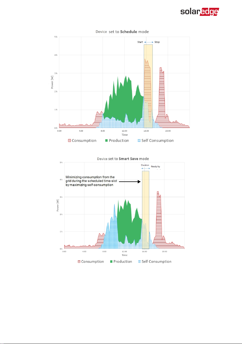
Figure 2: Examples of device operation
To enable the Smart Energy Hot Water functionality, the following supporting devices
must be installed:
Smart Energy Socket
8 Overview

Energy Meter:
Energy Meter with Modbus Connection. Refer to:
http://www.solaredge.com/files/pdfs/solaredge-meter-installation-guide.pdf
or
http://www.solaredge.com/files/pdfs/solaredge-meter-installation-guide-
na.pdf
Energy Meter with Cellular Connection. Refer to
https://www.solaredge.com/sites/default/files/se_energy_meter_cellular_na.pdf
ZigBee Plug-in for Smart Energy. Refer to:
https://www.solaredge.com/sites/default/files/se-device-control-zigbee-module-
installation-guide.pdf
https://www.solaredge.com/sites/default/files/se-zigbee-plug-in-for-setapp-
installation-guide.pdf
Installation
Figure 3: The Smart Energy Socket
Overview 9
Smart Energy Socket
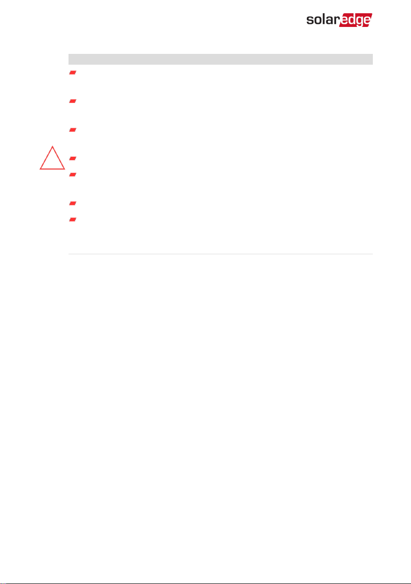
CAUTION!
This product must be operated under the specified operating
specifications, as described in the latest technical specification datasheet.
Configure the product so that the load connected is not switched on or off
more frequently than specified by the load manufacturer.
Do not connect loads that require a continuous current supply (e.g. fridge,
freezer).
Do not use the product if it is damaged or malfunctioning.
Never connect loads that can cause injuries or fire if they are switched on
unintentionally (e.g. an iron).
Do not let the product come into contact with water or other liquids.
The enclosed documentation is an integral part of this product. Keep the
documentation in a convenient place for future reference and observe all
instructions contained therein.
Plug the device into a wall socket , at a maximum distance of 50 m from the inverter.
Smart Energy Socket
10 Installation
Configuration
Smart Energy is configured in the inverter, as described herein.
Smart Energy is supported for the following:
Inverters with LCD screen - from firmware version 3.24xx. Refer to
Configuration
with Inverters with LCDScreen
on page 11.
Inverters with SetApp configuration - from firmware version 4.5.xx. Refer to
Configuration with Inverters with LCDScreen
on page 11.
For detailed information about various use cases, refer to
https://www.solaredge.com/sites/default/files/home_energy_management_immersion_
heater_controller_use_cases_app_note.pdf.
NOTE
Verify that the inverter has a ZigBee Plug-in installed and is connected to the
monitoring platform (refer to the
Inverter Installation Guide
for details on
setting up communication).
Configuration with Inverters with LCDScreen
Required inverter Firmware CPUversion : v3.24xx and later.
To associate the device with the inverter using the inverter LCDuser buttons:
1. Enter the inverter Setup mode as described in the
Inverter Installation Guide
.
2. Select Communication è ZigBee Conf..
3. Select:
Device Type è HA (Home Automation)
Protocol è HAM (Home Automation)
When HA Device Type is selected, a Device Manager menu item will appear in the
main configuration menu:
C o u n t r y < I t a l y >
L a n g u a g e < E n g >
C o m m u n i c a t i o n
P o w e r C o n t r o l
D i s p l a y
M a i n t e n a n c e
I n f o r m a t i o n
4. From the main menu select Device Manager. The Device Manager screen is
displayed:
Configuration 11
Smart Energy Socket
A d d D e v i c e s < 0 >
5. Select Add Devices to start the device association with the inverter.
6. Press the association button on the Smart Energy Hot Water.
The Device Manager LCDscreen should display a new line for each discovered
device, including the 3 last digits of its serial number, operating mode and operating
state. Discovery time may take up to 3 minutes. You can press the inverter LCDlight
button or the internal ESC button to exit the discovery process when all devices are
discovered.
A d d D e v i c e s < 3 >
S E - R E G x x x < A u t o , O F F >
S E - R E G - 3 6 x x < A u t o , O F F >
S E - S W x x x < M a n , O F F >
S E - S - P L G x x x < M a n O F F >
R e m o v e A l l
Device types:
SE-REG-36 - 3.6 kW Smart Energy Hot Water
SE-SW - Smart Energy Relay
SE-S-PLG - Smart Energy Socket
SE-S-SW - Smart Energy Switch
7. Select the device. The device configuration screen is displayed:
M o d e < M a n u a l >
S t a t e < O F F >
D e v i c e I n f o
R e m o v e D e v i c e
For the following device configuration steps, you can use either the inverter
LCDbuttonsor the monitoring platform/ app. The steps herein show configuration
using the inverter LCD.
For configuring using the monitoring platform, refer to
https://www.solaredge.com/sites/default/files/configuring_device_control_with_
the_monitoring_app.pdf
8. Select Mode. The mode configuration screen is displayed:
M a n u a l
A u t o
Smart Energy Socket
12 Configuration with Inverters with LCDScreen
Manual - turns the device to ONor OFF, as described below
Auto - allows setting two types of schedules for Home Energy Management, as
described in the next sections:
Smart Save - set the device operation requirements (ReadyBy and Duration
values). This mode is useful for maximizing self-consumption using excess
PVpower: the device operates autonomously based on configured settings.
Schedule - set the device start and stop times regardless of available excess
PVpower.
To set Manual mode:
1. Select Mode è Manual
2. Select ON or OFFto turn the device on or off.
To set Auto mode:
1. Select Auto. The following screen is displayed, showing options for setting the
device parameters:
M o d e < A u t o >
U s e E x c e s s P V < Y >
A d d S c h e d u l e
D e v i c e P r o p e r t i e s
D e v i c e I n f o
R e m o v e D e v i c e
2. Select Device Properties and set the following properties:
L o a d R a t i n g < x . x K W >
E x p o r t T H < x x x x W >
I m p o r t T H < x x x x W >
M i n O n T i m e < x x x >
Load Rating - the rated power (in kW) of the appliance
Export TH (threshold) - optional; the minimum power (in W) above which the
excess PV power will be diverted to the appliance. This value can be lower than
the load rating. The default value is 5% above the Load Rating.
Import TH (threshold) - optional; the maximum power (in W) purchased from
the grid and diverted to the appliance. The default value is 5% of the Load
Rating.
Configuration 13
Smart Energy Socket
NOTE
If changing the Export TH and Import TH default values, make sure
they sum up to a value that equals or greater than the appliance Load
Rating value. Otherwise, the device will turn off when there is
insufficient power to divert to the appliance.
Min ONTime - (optional); the minimum duration (in minutes) the appliance
should remain ONonce switched on, even when no excess PVpower is
available. The default value is 5 minutes.
3. Select Use Excess PV. The following screen is displayed:
S e t < Y e s >
W e e k D a y s < 1 2 3 4 5 6 7 >
Set <Yes/ No> - automatically divert the excess PV to the device (default: Yes).
Week Days <optional> - days to repeat the settings (default: every day).
4. Select Add Schedule. The following screen is displayed, showing schedule setting
options. You can configure up to four different schedules.
S m a r t S a v e
S c h e d u l e
D i s a b l e
R e m o v e S c h e d u l e
Use Disable to deactivate a schedule or Remove Schedule to delete it.
5. Select and set one of the scheduling options:
Smart Save:
S e t < S m a r t >
R e a d y b y < 0 0 : 0 0 >
D u r a t i o n < 0 0 >
Ready by - requested energy must be diverted to the load by this time
(default: 00:00; format:hours:minutes).
Duration - minimum accumulated time the load must remain on (in
minutes; default: 00).
Schedule:
S e t < S c h e d u l e >
S t a r t T i m e < 0 0 : 0 0 >
E n d T i m e < 0 0 : 0 0 >
W e e k D a y s < 1 2 3 4 5 6 7 >
Smart Energy Socket
14 Configuration with Inverters with LCDScreen
Start/End Time - the time of day by which the Smart Energy Hot Water must
start/ complete its task of delivering energy to the load (default: 00:00;
format:hours:minutes). If these values are not set, only the excess PV power
is used.
Week Days (optional) - days to repeat the settings (default: every day).
NOTE
In Auto mode , if you configure overlapping time-frames between Schedule
and Smart Save options, Schedule mode takes precedence over the Smart Save
mode.
Configuration 15
Smart Energy Socket

Configuration with Inverters with SetApp
Required inverter Firmware CPUversion : v4.5xx and later.
To associate the device with the inverter using SetApp:
1. Access SetApp as described in the
Inverter Installation Guide
.
2. Select Commissioning è Communication è Device Manager. The Smart Energy
Manager screen is displayed:
Device Manager
Add Device 2 connected ›
ZED-814 Manual, Off ›
Plug 409 Auto, On ›
Remove All ›
3. Select Add Devices to start the device association with the inverter.
4. Press the association button on the Smart Energy Hot Water.
The Smart Energy Manager screen should display a new line for each discovered
device, including the 3 last digits of its serial number, operating mode and operating
state. Discovery time may take up to 3 minutes. You can tap the Stop button to exit
the discovery process when all devices are discovered.
5. Select the device from the list. The device configuration screen is displayed (menus
vary depending on the device type):
Smart Energy Socket
16 Configuration with Inverters with SetApp
Plug 409
Mode Auto ›
Use Excess PV Yes ›
Schedule 1 Enabled ›
Schedule 2 Enabled ›
Add Schedule ›
Device Properties ›
Device info ›
Remove Device ›
6. Select Mode. The mode configuration screen is displayed. Select one of the
following:
Manual - turns the device to ONor OFF
Auto - allows setting two types of schedules for Home Energy Management, as
described in the next sections:
Smart Save - set the device operation requirements (ReadyBy and Duration
values). This mode is useful for maximizing self-consumption using excess
PVpower: the device operates autonomously based on configured settings.
Schedule - set the device start and stop times regardless of available excess
PVpower.
7. Select Use Excess PV. Set the following:
Select <Yes/ No> - automatically divert the excess PV to the device (default:
Yes).
Week Days <optional> - days to repeat the settings (default: every day).
8. If you selected the Auto option, select Schedule 1 and edits the schedule settings as
necessary. Use Disable to deactivate a schedule or Remove Schedule to delete it.
You can configure up to four different schedules.
9. Select and set one of the scheduling options:
Configuration 17
Smart Energy Socket

Smart Save:
Ready by - requested energy must be diverted to the load by this time
(default: 00:00; format:hours:minutes).
Duration - minimum accumulated time the load must remain on (in
minutes; default: 00).
Schedule:
Start/End Time - the time of day by which the Smart Energy Hot Water must
start/ complete its task of delivering energy to the load (default: 00:00;
format:hours:minutes). If these values are not set, only the excess PV power
is used.
Week Days (optional) - days to repeat the settings (default: every day).
10. To use multiple schedules select Add Schedule and edit the settings.
11. Select Device Properties and set the following properties:
Load Rating - the rated power (in kW) of the appliance
Min ONTime - (optional); the minimum duration (in minutes) the appliance
should remain ONonce switched on, even when no excess PVpower is
available. The default value is 5 minutes.
Export Threshold - optional; the minimum power (in W) above which the excess
PV power will be diverted to the appliance. This value can be lower than the
load rating. The default value is 5% above the Load Rating.
Import Threshold - optional; the maximum power (in W) purchased from the
grid and diverted to the appliance. The default value is 5% of the Load Rating.
NOTE
If changing the Export Threshold and Import Threshold default values,
make sure they sum up to a value that equals or greater than the
appliance Load Rating value. Otherwise, the device will turn off when
there is insufficient power to divert to the appliance.
Smart Energy Socket
18 Configuration with Inverters with SetApp
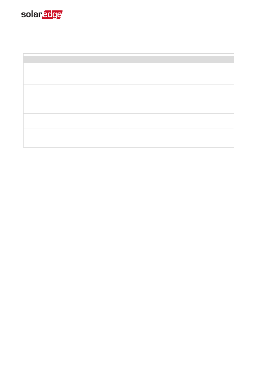
Modifying the Device Operation Mode and Schedules
You can re-configure the device operation mode and schedules at any time:
To Do this
Manually turn the load on or off
Select the device from the Device Manager
screen. Select Mode è Manual and set the
device to either ON or OFF.
Modify the schedule configuration
Select the device from the Device Manager
screen. Select Mode è Auto and set the
parameters of any menu: Smart
Save/Schedule.
Disable or delete a schedule Select Disable or Remove Schedule from the
Schedule screen.
Disconnect the device(s) from the
network
Select Remove Device or Remove All from the
device screen.
Configuration 19
Smart Energy Socket
Table of contents
Other SolarEdge Accessories manuals

Popular Accessories manuals by other brands


senva
senva TG Series installation instructions

Royal Sovereign
Royal Sovereign RMF-BC-46SS owner's manual

Clas Ohlson
Clas Ohlson TI-306 manual

Klarstein
Klarstein 10033598 instruction manual

Extron electronics
Extron electronics Universal Video Interface with Audio RGB 201... user guide

Pepperl+Fuchs
Pepperl+Fuchs RLG28 Series manual


