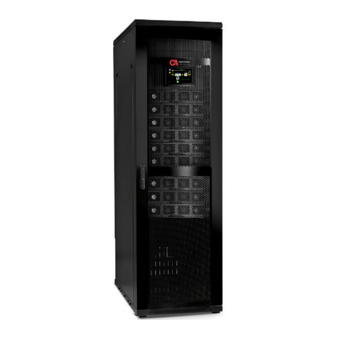
SolarEdge Critical Power B300 User manual

THREE-PHASE MODULAR UPS
FOR THE 400V GRID
B300
USER GUIDE
Revision 4, April 2021 (Doc. 2MUM-B300U)
This user guide is for
products B300

3
UPS for 400 Vac Grid, User Guide, doc. rev. 4
TABLE OF CONTENTS
1. SAFETY PRECAUTIONS ............................................................................................................................... 12
1.1. DO’S...............................................................................................................................................................12
1.2. DON’TS............................................................................................................................................................14
2. SOLAREDGE THREE PHASE MODULAR UPS FOR 400VAC ............................................................................ 15
2.1. SYSTEM STRUCTURE............................................................................................................................................16
3. OVERVIEW OF SYSTEM COMPONENTS....................................................................................................... 19
3.1. SYSTEM CONTROLLER..........................................................................................................................................19
3.2. UPS MODULE (30 KVA /30 KW) ........................................................................................................................19
3.3. STATIC SWITCH MODULE......................................................................................................................................19
3.4. BATTERY ..........................................................................................................................................................20
4. OVERVIEW OF OPERATING MODES............................................................................................................ 21
4.1. NORMAL MODE.................................................................................................................................................21
4.2. BATTERY MODE .................................................................................................................................................21
4.3. BYPASS MODE ...................................................................................................................................................21
4.4. ECO MODE ......................................................................................................................................................21
4.5. (OPTIONAL)MAINTENANCE BYPASS MODE.............................................................................................................22
5. EMERGENCY POWER OFF –EPO (MANUAL)............................................................................................... 23
5.1. POWER-OFF BUTTON (POB)................................................................................................................................23
5.2. EPO INDICATION ...............................................................................................................................................23
5.3. BATTERY TRIP COIL DRY CONTACT ..........................................................................................................................23
5.4. RESTARTING THE UPS AFTER EPO ........................................................................................................................24
6. UPS USER INTERFACE................................................................................................................................. 25
6.1. SYSTEM MENU (LCD HOME)SCREEN .....................................................................................................................25
6.2. SYSTEM MENU HIGHLIGHTS..................................................................................................................................26
6.2.1. Operation menu ...................................................................................................................................27
6.2.2. Status menu .........................................................................................................................................27
6.2.3. Setup menu ..........................................................................................................................................28
6.2.3.1. Time ................................................................................................................................................................. 29
6.2.3.2. Dry contacts .....................................................................................................................................................30
6.2.4. Profile menu .........................................................................................................................................30
6.2.5. Log menu..............................................................................................................................................31
6.3. OPERATING THE UPS .........................................................................................................................................31
6.3.1. Turn on UPS..........................................................................................................................................31
6.3.2. Turn off UPS .........................................................................................................................................32
6.3.3. Turn off power modules .......................................................................................................................32
6.3.4. Turn on power modules........................................................................................................................32
6.3.5. Transfer load to bypass ........................................................................................................................33
6.3.6. Transfer load to inverter ......................................................................................................................33
6.3.7. Battery test...........................................................................................................................................33
6.3.8. Turn on ECO Mode ...............................................................................................................................33

UPS for 400 Vac Grid, User Guide, doc. rev. 4
4
6.3.9. Turn off ECO Mode ...............................................................................................................................34
7. UPS START-UP/SHUTDOWN ...................................................................................................................... 35
7.1. SWITCH ON UPS (NOT FIRST-TIME START-UP) .........................................................................................................35
7.2. UPS TOTAL SHUTDOWN (NO AC OUTPUT)..............................................................................................................36
8. UPS MENU FUNCTIONS.............................................................................................................................. 37
8.1. PASSWORD REQUIREMENTS.................................................................................................................................39
8.2. SETUP MENU.....................................................................................................................................................40
8.2.1. Setup > System .....................................................................................................................................40
8.2.1.1. Setup > System > Nominal settings..................................................................................................................41
8.2.1.2. Setup > System > Number of modules.............................................................................................................42
8.2.1.2.1. Redundancy ................................................................................................................................................42
8.2.1.3. Setup > System > System type .........................................................................................................................43
8.2.1.3.1. Model type..................................................................................................................................................43
8.2.1.3.2. Multi-system mode.....................................................................................................................................43
8.2.1.3.3. ECO mode ...................................................................................................................................................43
8.2.1.3.4. Self-loading mode.......................................................................................................................................44
8.2.1.4. Setup > System > Shutdown and Autorestart ..................................................................................................44
8.2.1.5. Setup > System > Controller.............................................................................................................................45
8.2.1.5.1. Internal adaptor status ............................................................................................................................... 45
8.2.1.5.2. Audio test.................................................................................................................................................... 45
8.2.1.5.3. Screen saver setup......................................................................................................................................45
8.2.1.6. Setup > System > Maintenance........................................................................................................................45
8.2.1.6.1. Maintenance alarm list ...............................................................................................................................46
8.2.1.6.2. Maintenance alarm setup...........................................................................................................................46
8.2.1.6.3. Set last maintenance date ..........................................................................................................................46
8.2.1.6.4. System snapshot......................................................................................................................................... 46
8.2.1.6.5. Start logging................................................................................................................................................46
8.2.2. Setup > Modules...................................................................................................................................46
8.2.2.1. AC input voltage calibration............................................................................................................................. 47
8.2.2.2. AC output voltage calibration .......................................................................................................................... 48
8.2.2.3. Modules input current calibration ...................................................................................................................48
8.2.2.4. Modules output current calibration.................................................................................................................48
8.2.2.5. DC voltage calibration ......................................................................................................................................49
8.2.2.6. AC output voltage Adjustment.........................................................................................................................49
8.2.2.7. DC bus voltage calibration................................................................................................................................52
8.2.2.8. DC voltage adjustment.....................................................................................................................................52
8.2.2.9. Serial number................................................................................................................................................... 52
8.2.2.10. Auto correction ................................................................................................................................................ 53
8.2.2.11. Power walk-in................................................................................................................................................... 54
8.2.3. Setup > Battery.....................................................................................................................................55
8.2.3.1. Setup > Battery > Battery test parameters.......................................................................................................57
8.2.3.1.1
.Battery test fault voltage ............................................................................................................................58
8.2.3.1.2. Rectifier voltage during battery test........................................................................................................... 59
8.2.3.1.3. Automatic battery test interval................................................................................................................... 59
8.2.3.1.3.1. Factors that can delay the automatic battery test.............................................................................. 60
8.2.3.1.4. Maximum duration of battery test ............................................................................................................. 60
8.2.3.1.5. Next battery test start time ........................................................................................................................ 60
8.2.3.1.6. Enable/Disable battery test by current.......................................................................................................60
8.2.3.2. Setup > Battery > Battery current ....................................................................................................................61
8.2.3.2.1. Enable/Disable current sensors .................................................................................................................. 61

5
UPS for 400 Vac Grid, User Guide, doc. rev. 4
8.2.3.2.2. Set battery current limit value.................................................................................................................... 61
8.2.3.2.3. Minimum DC voltage at current limit .........................................................................................................62
8.2.3.3. Setup > Battery end-of-backup voltage limit ...................................................................................................63
8.2.3.4. Setup > Battery > Battery low limit voltage......................................................................................................64
8.2.3.5. Setup > Battery > Battery capacity in Ah..........................................................................................................64
8.2.3.6. Setup > Battery > Battery temperature control ...............................................................................................65
8.2.3.6.1. Setup > Batt. > Batt. Temp. Cntl. > Temp sensors yes/no........................................................................... 67
8.2.3.6.2. Setup > Batt. > Batt. Temp. Cntl. > Enable/disable batt. temp. comp. ....................................................... 67
8.2.3.6.3. Setup > Batt. > Batt. Temp. Cntl. > Batt. temp. comp. parameters ............................................................ 67
8.2.3.6.3.1. Temp. compensation factor for a single battery block .......................................................................67
8.2.3.6.3.2. Low limit DC voltage at compensation................................................................................................67
8.2.3.6.3.3. High limit DC voltage at compensation............................................................................................... 67
8.2.3.7. LVD battery protector ...................................................................................................................................... 67
8.2.4. Setup > STSW........................................................................................................................................68
8.2.4.1. Setup > STSW > Calibrate bypass voltage......................................................................................................... 70
8.2.4.2. Setup > STSW > Calibrate output voltage......................................................................................................... 70
8.2.4.3. Setup > STSW > High-level setup......................................................................................................................70
8.2.4.3.1. Setup > STSW > Hi-level setup > Bypass forced/controlled ........................................................................71
8.2.4.3.2. Setup > STSW > Hi-level setup > STSW integration time............................................................................. 71
8.2.4.3.3. Setup > STSW > Hi-level setup > Bypass voltage range............................................................................... 71
8.2.4.4. Setup > STSW > Overload hysterisis ................................................................................................................. 71
8.2.4.5. Setup > STSW > Enable / disable analysis event...............................................................................................72
8.2.4.6. Setup > STSW > Sync fault delay transfer.........................................................................................................73
8.2.5. Setup > Alarms .....................................................................................................................................74
8.2.5.1. Setup > Alarms > Alarms configuration............................................................................................................75
8.2.5.2. Setup > Alarms > Set limits............................................................................................................................... 76
8.2.5.2.1. Setup > Alarms > Set Limits > DC limits....................................................................................................... 77
8.2.5.2.2. Setup > Alarms > Set Limits > AC limits.......................................................................................................78
8.2.5.2.3. Setup > Alarms > Set Limits >Temperature limits ....................................................................................... 78
8.2.6. Setup > Connectivity.............................................................................................................................80
8.2.6.1. (Optional) Setup > Connectivity > Network configuration ............................................................................... 80
8.2.6.2. Network configuration options ........................................................................................................................ 81
8.2.6.2.1. Network configuration > Obtain IP address automatically ......................................................................... 81
8.2.6.2.2. Network configuration > Use static IP address ...........................................................................................81
8.2.6.3. (Optional feature) SNMP configuration options ..............................................................................................81
8.2.6.4. (Optional feature) Setup > Connectivity > Serial Communication.................................................................... 83
8.2.6.5. (Optional feature) Modbus ..............................................................................................................................83
8.2.6.5.1. Defining a TCP Modbus link ........................................................................................................................84
8.2.6.5.2. Defining a serial Modbus link......................................................................................................................84
8.2.6.6. (Optional feature) Email configuration ............................................................................................................85
8.2.6.6.1. Adding a new email recipient ..................................................................................................................... 88
8.2.6.7. Controller host name .......................................................................................................................................91
8.2.7. Setup > Time.........................................................................................................................................91
8.2.7.1. Adjust date / time ............................................................................................................................................92
8.2.7.2. Setup > Time > Adjust date / time....................................................................................................................92
8.2.7.3. Setup > Time > Change time zone....................................................................................................................93
8.2.7.4. Setup > Time > Time Synchronization .............................................................................................................. 93
8.2.7.5. Setup > Time > Set last maintenance date.......................................................................................................93
8.2.8. Setup > Site ID ......................................................................................................................................94
8.2.9. (Optional feature) Setup > Dry contacts...............................................................................................95
8.2.9.1. Setup > Dry contacts > Input dry contacts ....................................................................................................... 96
8.2.9.1.1. Location of the input dry contacts..............................................................................................................96
8.2.9.1.2. Using the input dry contacts....................................................................................................................... 97

UPS for 400 Vac Grid, User Guide, doc. rev. 4
6
8.2.9.2. Setup > Dry contacts > Output dry contacts .................................................................................................... 98
8.2.9.2.1. Location of the output dry contacts..........................................................................................................101
8.2.9.2.2. Output dry contacts in action ...................................................................................................................101
8.2.9.2.3. Testing an output dry contact...................................................................................................................101
8.2.9.3. Generator Mode setup...................................................................................................................................101
8.2.10. Setup > Save and Restore ...................................................................................................................102
8.2.10.1. Setup > Save & restore > Save settings ..........................................................................................................103
8.2.10.2. Setup > Save & restore > Restore settings .....................................................................................................103
8.2.10.3. Setup > Save & restore > Restore factory settings .........................................................................................103
8.2.11. Setup > Change authorization level....................................................................................................104
8.2.11.1. Setup > Authorization > Set user authorization level.....................................................................................104
8.2.11.2. Setup > Authorization > Enable / Disable remote control..............................................................................104
8.2.11.3. Setup > Authorization > Operations Authorization ........................................................................................ 105
8.3. OPERATION MENU ...........................................................................................................................................106
8.3.1. Operation > Turn on/off > System on/off...........................................................................................107
8.3.1.1. Operation > Turn on/off > System on ............................................................................................................ 107
8.3.1.2. Operation > Switch on/off > System off......................................................................................................... 109
8.3.2. Operation > Turn on/off > modules on/off.........................................................................................109
8.3.2.1. Operation > Turn on/off > Modules off..........................................................................................................109
8.3.2.2. Operation > Switch on/off > Modules On ...................................................................................................... 111
8.3.3. Operation > Turn on/off > Controller restart/Shutdown ....................................................................112
8.3.3.1. Operation > Turn on/off > Controller restart ................................................................................................. 112
8.3.3.2. Operation > Turn on/off > Controller shutdown............................................................................................ 112
8.3.4. Operation > Transfer load ..................................................................................................................114
8.3.4.1. Operation > Transfer load > Transfer load to inverter ...................................................................................114
8.3.4.2. Operation > Transfer load > Transfer load to bypass ..................................................................................... 114
8.3.5. Operation > Battery test.....................................................................................................................115
8.3.6. Operation > Turn eco mode on/off.....................................................................................................116
8.3.7. Operation > UPS software upgrade....................................................................................................120
8.4. STATUS MENU.................................................................................................................................................125
8.5. PROFILE MENU ................................................................................................................................................129
8.5.1. Profile > System..................................................................................................................................129
8.5.2. Profile > Battery .................................................................................................................................130
8.5.3. Profile > STSW ....................................................................................................................................131
8.5.4. Profile > Alarms ..................................................................................................................................132
8.5.5. Profile > Identification ........................................................................................................................133
8.6. LOG MENU ....................................................................................................................................................134
8.6.1. The Alarms button on the log detail screen .......................................................................................137
8.7. CONNECTIVITY MENU........................................................................................................................................138
8.8. TIME MENU ....................................................................................................................................................139
8.9. LANGUAGE MENU ............................................................................................................................................140
9. PREVENTIVE MAINTENANCE.................................................................................................................... 141
10. (APPENDIX) HOLDING REGISTERS FOR MODBUS QUERIES....................................................................... 142

7
UPS for 400 Vac Grid, User Guide, doc. rev. 4
LIST OF FIGURES
Figure 1: B300 Model –Major Components (Front View)............................................................................ 16
Figure 2: Connection Terminals (perspective view)...................................................................................... 17
Figure 3: B300 model - Connection terminals (rear view) ........................................................................... 17
Figure 4: System menu screen ..................................................................................................................... 25
Figure 5: Operation option............................................................................................................................ 27
Figure 6: Status option .................................................................................................................................. 27
Figure 7: The Status screen .......................................................................................................................... 28
Figure 8: Setup option................................................................................................................................... 29
Figure 9: Time option .................................................................................................................................... 29
Figure 10: Dry Contacts option ..................................................................................................................... 30
Figure 11: Profile option................................................................................................................................ 30
Figure 12: Log option..................................................................................................................................... 31
Figure 13: Turn on UPS option ...................................................................................................................... 32
Figure 14: Turn off UPS option...................................................................................................................... 32
Figure 15: Turn off power modules option................................................................................................... 32
Figure 16: Turn on power modules option ................................................................................................... 32
Figure 17: Transfer load to bypass option..................................................................................................... 33
Figure 18: Transfer load to inverter option................................................................................................... 33
Figure 19: Battery Test option....................................................................................................................... 33
Figure 20: ECO mode on................................................................................................................................ 33
Figure 21: ECO mode off option.................................................................................................................... 34
Figure 22: System menu, UPS off.................................................................................................................. 35
Figure 23: LCD control panel, displays the System menu ............................................................................. 37
Figure 24: Navigation trail to the Time function........................................................................................... 38
Figure 25: UPS System menu ........................................................................................................................ 39
Figure 26: Key icon on Email Configuration .................................................................................................. 39
Figure 27: Setup menu .................................................................................................................................. 40
Figure 28: Setup > SYSTEM menu hierarchy ................................................................................................. 41
Figure 29: Setup > Shutdown and Autorestart ............................................................................................. 45
Figure 30: Setup > Modules menu hierarchy................................................................................................ 47
Figure 31: Setup > Modules menu options ................................................................................................... 47
Figure 32: Output terminals.......................................................................................................................... 50
Figure 33: AC Output Voltage Calibration..................................................................................................... 51
Figure 34: Serial Number screen................................................................................................................... 53
Figure 35: Auto correction ............................................................................................................................ 54
Figure 36: Power Walk-In screen .................................................................................................................. 55
Figure 37: Setup, Battery menu options ....................................................................................................... 56
Figure 38: Setup > Battery menu hierarchy ................................................................................................. 57
Figure 39: Battery, Battery Test menu options............................................................................................. 58
Figure 40: Battery Test Fault Voltage............................................................................................................ 58
Figure 41: Rectifier voltage at Battery Test................................................................................................... 59
Figure 42: Automatic Battery Test Period..................................................................................................... 59

UPS for 400 Vac Grid, User Guide, doc. rev. 4
8
Figure 43: Next Battery Test Start Time........................................................................................................ 60
Figure 44: Setup, Battery, Battery Current ................................................................................................... 61
Figure 45: Enable/Disable Current Sensors................................................................................................... 61
Figure 46: Battery Current Limit Value.......................................................................................................... 62
Figure 47: Minimum DC voltage at current value......................................................................................... 63
Figure 48: Setup, Battery End of backup voltage limit.................................................................................. 63
Figure 49: Battery, Battery low limit voltage ................................................................................................ 64
Figure 50: Battery, Battery capacity.............................................................................................................. 65
Figure 51: Battery, Battery Temperature Control......................................................................................... 66
Figure 52: Battery, Temperature compensation parameters....................................................................... 66
Figure 53: Battery, LVD battery protector .................................................................................................... 68
Figure 54: Static Switch menu options.......................................................................................................... 69
Figure 55: Setup > Static Switch options...................................................................................................... 69
Figure 56: Setup > STSW > High-level setup................................................................................................. 70
Figure 57: Static switch, Overload Hysteresis............................................................................................... 72
Figure 58: Static Switch, Enable/Disable Analysis Event............................................................................... 73
Figure 59: STSW > Sync fault delay transfer.................................................................................................. 73
Figure 60: Setup, Alarms menu options........................................................................................................ 74
Figure 61: Setup > Alarms options ............................................................................................................... 75
Figure 62: Setup, Alarms, Alarms Configuration, Restore Factory Settings.................................................. 76
Figure 63: Alarms, Alarm Limits .................................................................................................................... 77
Figure 64: Alarms limit, DC voltage limit configuration................................................................................ 77
Figure 65: Alarm limits, AC voltage configuration ........................................................................................ 78
Figure 66: Alarms limit, temperature configuration..................................................................................... 79
Figure 67: Setup > Connectivity options ...................................................................................................... 80
Figure 68: Setup > Connectivity > SNMP configuration options .................................................................. 82
Figure 69: Creating a new host..................................................................................................................... 82
Figure 70: Defining serial communication parameters................................................................................ 83
Figure 71: Defining Modbus communication parameters ........................................................................... 84
Figure 72: Example of email message body................................................................................................. 85
Figure 73: The email configuration menu .................................................................................................... 86
Figure 74: Add new email recipients screen................................................................................................. 88
Figure 75: New email recipient screen......................................................................................................... 89
Figure 76: Alarms button on email recipient screen.................................................................................... 90
Figure 77: Alarm selection screen for email recipient ................................................................................. 90
Figure 78: Setup, Time menu options ........................................................................................................... 91
Figure 79: Setup > Time options................................................................................................................... 92
Figure 80: Setup, Time, Adjust Date/Time.................................................................................................... 92
Figure 81: Setup, Time, Time Synchronization.............................................................................................. 93
Figure 82: Setup, Assign Site ID..................................................................................................................... 94
Figure 83: Setup, Dry Contacts menu............................................................................................................ 95
Figure 84: Setup > Dry Contacts option ....................................................................................................... 96
Figure 85: Defining an input dry contact...................................................................................................... 97

9
UPS for 400 Vac Grid, User Guide, doc. rev. 4
Figure 86: Setup, Output Dry Contacts ......................................................................................................... 98
Figure 87: Example of an output dry contact linked to an alarm............................................................... 101
Figure 88: Generator Mode Setup screen.................................................................................................. 102
Figure 89: Setup > Save & Restore options................................................................................................ 103
Figure 90: Setup, Authorization .................................................................................................................. 104
Figure 91: Setup, Authorizations operations .............................................................................................. 105
Figure 92: The Operation option on the System menu............................................................................... 106
Figure 93: Operation menu......................................................................................................................... 107
Figure 94: Turn off/on menu...................................................................................................................... 108
Figure 95: Confirm dialog, Turn all modules on ......................................................................................... 109
Figure 96: Turn on/off, Modules off............................................................................................................ 110
Figure 97: Turn on/off, Modules on............................................................................................................ 111
Figure 98: Switch on/off - Controller Restart.............................................................................................. 112
Figure 99: Switch on/off - Controller Shutdown......................................................................................... 113
Figure 100: Controller Reset Button on the Back of the Controller............................................................ 113
Figure 101: Transfer load ............................................................................................................................ 114
Figure 102: Transfer load to bypass............................................................................................................ 115
Figure 103: Operation, Battery Test............................................................................................................ 116
Figure 104: Operation, Battery Test............................................................................................................ 117
Figure 105: UPS is On but ECO mode is not turned on ............................................................................... 118
Figure 106: UPS is on, ECO mode is turned on and inverter is in standby state......................................... 119
Figure 107: UPS is ON, UPS is on and ECO mode/Inverter is in active state............................................... 120
Figure 108: Required system off prompt .................................................................................................... 121
Figure 109: Select unit for upgrade............................................................................................................. 122
Figure 110: Insert USB screen ..................................................................................................................... 123
Figure 111: USB port locations.................................................................................................................... 123
Figure 112: Inverter upgrade screen........................................................................................................... 124
Figure 113: PFC upgrade screen.................................................................................................................. 125
Figure 114: System menu > Status option ................................................................................................. 125
Figure 115: The Status Screen.................................................................................................................... 126
Figure 116: System menu > Profile options ................................................................................................ 129
Figure 117: Profile, System.......................................................................................................................... 129
Figure 118: Profile, Battery ......................................................................................................................... 130
Figure 119: Profile, Static Switch................................................................................................................. 131
Figure 120: Profile, Alarms.......................................................................................................................... 132
Figure 121: Profile, Identification................................................................................................................ 133
Figure 122: System menu > Log options .................................................................................................... 134
Figure 123: Listing of the log file contents................................................................................................. 135
Figure 124: Log record - detailed display ................................................................................................... 136
Figure 125: Alarms display, from the Log detail screen............................................................................. 137
Figure 126: System menu > Connectivity option ....................................................................................... 138
Figure 127: Connectivity display from System menu................................................................................. 138
Figure 128: System menu > Time option.................................................................................................... 139

UPS for 400 Vac Grid, User Guide, doc. rev. 4
10
Figure 129: Time function on the System menu......................................................................................... 139
Figure 130: System menu > Language option ............................................................................................ 140
LIST OF TABLES
Table 1: Key to Figure 3................................................................................................................................ 17
Table 2: Key to Figure 4................................................................................................................................ 25
Table 3: Description of email parameters.................................................................................................... 87
Table 4: Alarms that can trigger output dry contacts .................................................................................. 98
Table 5: Key to Figure 115 (the Status screen)........................................................................................... 126
Table 6: Log message types (alarm types).................................................................................................. 134
Table 7: Holding Registers for Modbus queries.......................................................................................... 142

11
UPS for 400 Vac Grid, User Guide, doc. rev. 4
STANDARDS AND CONVENTIONS
This user manual contains diagrams which include images of the display screen of the
UPS. Unless otherwise indicated, the readings shown in the screen images are only
illustrative, and are not intended to match the readings on a specific system in any
particular environment.
Operation and control of the UPS is accomplished through a touch-sensitive LCD display
screen. In this manual, when explaining how to navigate the control software via the
touch-sensitive screen, the terms "tap", "press", "choose", and "select" may be used
interchangeably to indicate selection of a screen option.

UPS for 400 Vac Grid, User Guide, doc. rev. 4
12
1. Safety Precautions
The UPS system is designed for a wide range of environments. Nevertheless, the modular UPS
should be handled with care, according to the following guidelines.
1.1. Do’s
Read this manual carefully before starting installation and operation of the UPS.
Review the safety precautions described below to avoid injury to users and damage to the
equipment.
This UPS is intended for installation in a temperature-controlled, indoor area that is free
from conductive contaminants.
All power connections must be completed by a licensed electrician who is experienced in
wiring this type of equipment, and who is familiar with the local electrical codes and
regulations. Improper wiring may cause damage to the equipment, injury to personnel, or
even death.
Ensure all power is disconnected before performing installation or maintenance.
See installation guide for recommended clearances.
The UPS must be well grounded to the building’s grounding system with a conductor that
has a current carrying capacity that matches the rating of the UPS.
Battery installation, battery maintenance, and battery replacement shall be performed only
by authorized service personnel.
Pay attention to all DANGER, CAUTION, and WARNING notices affixed to the inside and
outside of the UPS.
Keep the surroundings clean, uncluttered and free from excess moisture.
Keep the operating environment within the parameters stated in this document.
Allow only qualified service engineers to service the UPS. There are no user-serviceable
components. Do not try to repair it yourself!
Use the UPS only for its intended purpose.
The batteries should preferably be installed next to the UPS, or as close to it as is
practically possible.

13
UPS for 400 Vac Grid, User Guide, doc. rev. 4
If you remove a power module from the UPS while the module is operating, wait five
minutes before reinserting the module. This allows the module’s capacitors time to
discharge.
FAST FUSES (SEMICONDUCTOR FUSES) must be used between the battery and the UPS –
for example, the Ferraz Shawmut A70QS fuse.
WARNING - RISK OF LETHAL ELECTRIC SHOCK:
WARNING! HIGH TOUCH CURRENT!
EARTH CONNECTION ESSENTIAL BEFORE CONNECTING SUPPLY.
WARNING - RISK OF LETHAL ELECTRIC SHOCK:
The battery cabinet contains a series of batteries that provides high
voltage and energy in the UPS body even when the UPS is not
connected to the AC input.
Take appropriate precautions during installation, inspection and
servicing.

UPS for 400 Vac Grid, User Guide, doc. rev. 4
14
1.2. Don’ts
Do not open the cover of the UPS or the battery cabinets under any circumstances. All
UPS panels and doors should be closed.
Do not insert any objects through the ventilation holes.
Do not put objects on the UPS.
Do not move the UPS while it is operating.
Do not use the UPS outdoors.
Do not turn the UPS upside down or lying down during transportation.
Do not connect or disconnect any AC or DC cables to the battery cabinet or UPS unless
ALL the battery circuit and AC circuit breakers are turned OFF.
Do not turn ON the battery circuit breaker when the battery cabinet is disconnected from
the UPS.
Do not install the UPS next to gas or electrical heaters. A restricted location is
recommended in order to prevent access by unauthorized personnel.
If you remove a power module from the UPS while the module is operating, do not
reinsert the module immediately. Wait five minutes.
WARNING - RISK OF LETHAL ELECTRIC SHOCK:
This UPS receives power from more than one source!
Disconnection of all AC sources and DC sources is
required to de-energize this unit before servicing.
WARNING - RISK OF LETHAL ELECTRIC SHOCK:
Do not touch uninsulated battery terminals.

15
UPS for 400 Vac Grid, User Guide, doc. rev. 4
2. Solaredge three phase modular UPS for 400Vac
In general, an Uninterruptible Power Supply (UPS) provides backup power for use when the utility
AC electric power mains fail or drop to an unacceptable voltage level. A Solaredge UPS does this
and much more.
The Solaredge UPS protects your data and equipment and minimize downtime and other adverse
effects that can be incurred by power failures and other irregularities.
Voltage surges, spikes and sags are inherent in commercial utility power. Over time, these
irregularities shorten the life of equipment and components. The UPS continually eliminates
power irregularities, thus helping to extend the life of your equipment, even through normal use
when the mains power is constant and continuous.
The UPS requires very little attention or intervention during normal operation; however, you
should read and understand the procedures described in this manual to ensure trouble-free
operation.
The UPS employs active current balancing between its power modules, and delivers overall
electrical efficiency of up to 96 %, 98 % in backup mode and up to 99% in ECO mode.

UPS for 400 Vac Grid, User Guide, doc. rev. 4
16
2.1. System structure
Solaredge three phase modular UPS comes in various base models that have a maximum power
capacity of 300kVA. The UPS includes from one to ten UPS power modules, each supplying 30
kVA.
In addition to the power modules, the UPS includes:
1. A system controller
2. A static switch module
3. An LCD display screen
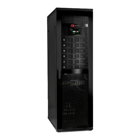
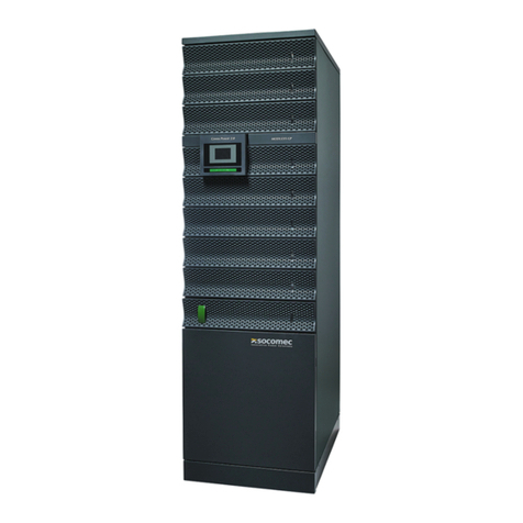
Figure 1: B300 Model –Major Components (Front View)
ITEM
DESCRIPTION
A
System Controller
B
Power modules

UPS for 400 Vac Grid, User Guide, doc. rev. 4
18
ITEM
DESCRIPTION
A
Protective earth (ground) bus bar
B
Neutral and midpoint terminals
C
AC RECTIFIER INPUT terminals (L1, L2, L3)
D
BYPASS INPUT terminals (L1, L2, L3)
E
AC OUTPUT terminals (L1, L2, L3)
F
BATTERY terminals (positive, midpoint, negative).

19
UPS for 400 Vac Grid, User Guide, doc. rev. 4
3. Overview of System Components
This section provides a brief overview of the role and function of the UPS primary components. It
includes the following sections:
1. System controller (includes LCD control panel)
2. UPS module (30 kVA / 30 kW)
3. Static switch module
4. Battery
3.1. System controller
The UPS system controller has three main functions, including to:
1. Control and monitor operation of the UPS according to user commands.
2. Collect and summarize data from all sections of the UPS.
3. Manage communication with external computers for data transfer and operation.
The UPS can operate without the system controller but with reduced
functionality.
The system controller includes the LCD control panel used to monitor and
operate the UPS.
3.2. UPS module (30 kVA / 30 kW)
The power module is the core of the UPS, which consists of from one to ten identical internal
modules operating in parallel. The number of UPS modules installed in the cabinet depends on
the user's capacity and redundancy requirements.
Each UPS module includes a 3-phase charger with PFC (power factor correction) and a 3-phase
PWM (pulse-width modulation) inverter connected to batteries by a classic DC link.
3.3. Static switch module
The centralized, electronic static switch enables an automatic transfer of the load from the output
of the inverters to an alternate source –the AC mains. As an example –when the inverter is
unable to supply sufficient power to the load (for example, in the event of an overload, or an
inverter failure). The static switch transfers high currents at very high speed; a typical transfer time
is less than 3 ms.

UPS for 400 Vac Grid, User Guide, doc. rev. 4
20
3.4. Battery
The UPS's battery bank provides backup power to the UPS and its load devices in the event that
the utility AC input fails. The batteries are housed in an external cabinet adjacent to the UPS. The
batteries are charged by the rectifier that supplies power to both the inverter and the battery
charger.
The battery cabinet should be installed as close to the UPS as is practically possible.
Fast-acting fuses (semiconductor fuses) must be used between the battery and the UPS.
Protect the batteries from moisture, dampness, and foreign substances.
A safe disconnect device must be used on each battery box.
The temperature of the battery's surroundings influences the batteries' useful lifetime.
The UPS supports the use of standard lead-acid batteries, and also lithium-ion batteries.
If you plan to use lithium-ion batteries you must supply your own BMS
(Battery Management System), and you must follow Solaredge special
instructions for lithium-ion battery setup.
The setup instructions are available from
https://criticalpower.solaredge.com/customer-service.
Table of contents
Other SolarEdge UPS manuals


