Solartron 7091 User manual

7061
SYSTEMS VOLTMETER
OPERATING MANUAL
'ssueC: Nov 1986 Part No. 70610012
Solartron Instruments, Victoria Road, Farnborough
Hampshire, England GU 14 7PW Telephone: Farnborough (0252) 544433
Telex: 858245 Solfar GCables: Solartron Farnborough
solartron pursues apoi'cy of continuous development and product improvement
he specification mthis document may therefore be changed without notice 19©86


Contents
Chapter 1General Information Page
1.1
lIntroduction 1.2
2Accessories 1.2
3The Configuration Switch 1.3
4Options 1.4
5Safety 1.5
6Connecting the ac mains 1.6
Chapter 2Getting Started 2.1
Chapter 3Front Panel Controls 3.1
1Introduction 3.3
2Front/rear switching 3.6
3Measurement keys 3.7
4Range keys 3.7
5Filter key 3.8
6Null key 3.8
7Ratio key 3.8
8Channel key 3.9
9Digits key 3.10
10 Track and trigger keys 3.10
11 General operating keys 3.13
12 Interface keys 3.13
13 Reset +enter &Menu +reset keys 3.14
14 Timer key 3.15
15 Scan key 3.17
16 Delay key 3.18
17 Probe key 3.18
18 Progs key 3.20
19 History key 3.28
Chapter 4Connections &Measurements 4.1
1General 4.2
2Voltage 4.2
3Current 4.3
4Resistance 4.3
5Drift correction 4.4
BRS/7061/2

Chapter 5Remote Control 5.1
1Introduction 5.3
2Remote commands and program names 5.4
3Interface command language 5.6
4Command set- verbose 5.6
5Command set -cryptic 5.37
6Programs 5.40
7Error messages 5.45
8Using the 7061 from the GPIB 5.46
9GPIB functions 5.54
Chapter 6Interference -some causes and cures 6.1
1Introduction 6.2
2Series mode interference 6.3
3Remedial action 6.3
Chapter? Specification 7.1
Chapter 8Calibration 8.1
Appendix AAdopted settings on power-up &reset
Appendix BMeasurement delay &integration times
Appendix COverload indication; display &output
formats
Index
BRS/7061/3

[Chap. 1
1
Chapter 1
General Information
Para. Pa8e
1Introduction 1-2
2Accessories 1-2
3The Configuration Switch 1-3
4Options 1-4
4.1 Scanner option 1-4
4.2 Memory option 1-4
5Safety 1-5
5.1 General Safety Precautions 1-5
5.2 Earthing 1-5
6Connecting the ac mains 1-6
6.1 Voltage Selector 1-6
6.2 Mains Fuses 1-7
6.3 Mains Lead 1-7
6.4 Connection Procedure 1-8
BRS/7061/2 1.1

[Chap. 1|
INTRODUCTION
The 7061 combines high speed digital electronics with microprocessor control to provide
afast, accurate systems voltmeter. With channel scanning, timer control and
measurement processing, the 7061 is ideally suited to automated test requirements
using the built-in IEEE 488 interface (GPIB) to give remote control.
The 7061 is equally at home as abench instrument, with scanning, timing and
processing facilities all controllable from the front panel. And, of course, straightforward
voltage, current and resistance measurements are easily made with great reliability and
accuracy.
Chapter 1of the manual deals with details relevant to the installation of the voltmeter.
Rack mounting is dealt with in Appendix D.
To make simple measurements, refer to Chapter 2, 'Getting Started'.
For more advanced measurements using processing facilities, but still under front panel
control, refer to Chapter 3, 'Front Panel Controls'.
To use the 7061 as aremotely controlled instrument via the GPIB, refer to Chapter 5,
'Remote Control'.
For information on making measurements, see Chapter 4.
Chapter 6contains the full specification and chapter 7gives calibration information.
ACCESSORIES
Supplied:
2-terminal input lead
Power lead
Copper crocodile clip (2)
Rack mounting brackets (2)
Operating manual
2-terminal reference lead
Spare fuses
Calibration key
Optional:
High voltage probe 70757
2-
terminal input lead 3187
3-
terminal input lead 3193
5-terminal input lead 3183
Kelvin input lead (4-terminal ohms) 70758 E
Low thermal input lead kit 70758 D
2-terminal reference lead 70617 B
4-
terminal reference lead 70617 D
Temperature probe, insertion PRT 70617 E
Telescopic rack slides (pair) 70759
Technical manual 70610011
1.2 BRS/7061/2

[Chap. 1|
3THE CONFIGURATION SWITCH
The configuration switch is adual in-line switch inside the instrument. Its settings are
shown in Fig. 1.1, with the example showing 50 Hz line frequency and 8channel
operation selected.
(5) SPARE
(4) SPARE
(3) 16/8 CHANNEL
(2) SPARE
(1) LINE FREQUENCY..
(0) LINE FREQUENCY..
1
—
Inn imt=m
M“=I i=*i
50 Hz 400 Hz 60 Hz 50 Hz
Fig. 1.1 Configuration switch settings
To reach the switch, disconnect the instrument from signal inputs and from the mams
supply before removing the top panel. This is held in place by four screws. The switch is
just behind the front panel, to the left of centre, as shown in Fig. 1.2. If the memory
expansion board is Fitted, this will have to be removed in order to reach the switch. It is
held in place by three screws.
Fig. 1.2 Plan view showing position of configuration switch
BRS/7061/2 1.3
[Chap. 1]
4OPTIONS
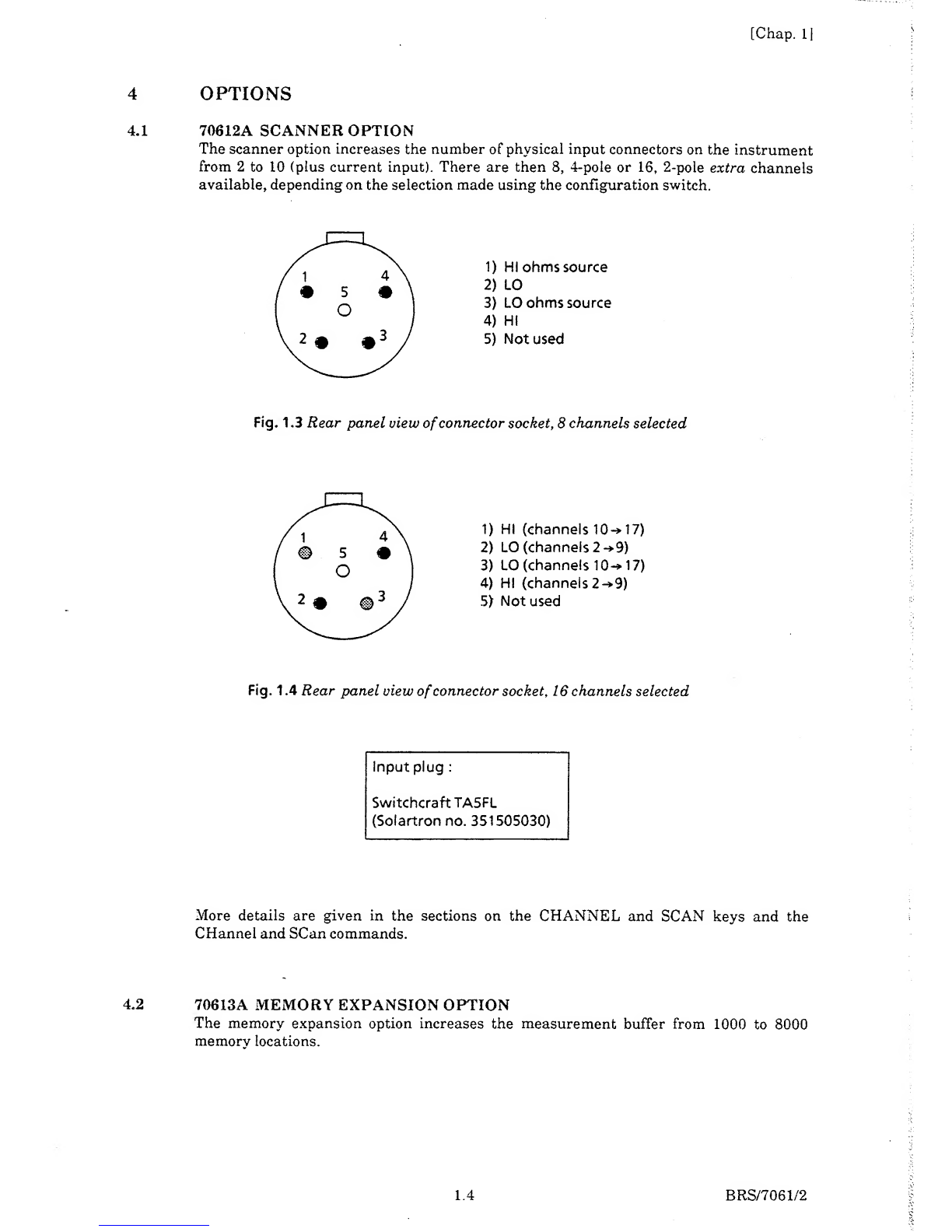
4.1 70612A SCANNER OPTION
The scanner option increases the number of physical input connectors on the instrument
from 2to 10 (plus current input). There are then 8, 4-pole or 16, 2-pole extra channels
available, depending on the selection made using the configuration switch.
1) HI ohms source
2) LO
3) LO ohms source
4) HI
5) Not used
Fig. 1.3 Rear panel view ofconnector socket, 8channels selected
1) HI (channels 10-» 17)
2) LO (channels 2-* 9)
3) LO (channels 10 17)
4) HI (channels 2-» 9)
5) Not used
Fig. 1.4 Rear panel view ofconnector socket, 16 channels selected
Input plug :
SwitchcraftTA5FL
(Solartron no. 351505030)
More details are given in the sections on the CHANNEL and SCAN keys and the
CHannel and SCan commands.
4.2 70613A MEMORY EXPANSION OPTION
The memory expansion option increases the measurement buffer from 1000 to 8000
memory locations.
1.4 BRS/7061/2

[Chap. 1
1
5SAFETY
The 7061 has been designed in accordance with the IEC publication 348 (Class 1), 'Safety
Requirement for Electronic Measurement Apparatus', and has been supplied in asafe
condition. This operating manual contains information and warnings which must be
followed in order to ensure safe operation and to keep the equipment in asafe condition.
The operating instructions include safety precautions where appropriate, but the
principal ones are also listed below.
5.1 GENERAL SAFETY PRECAUTIONS
1. Before switching on, ensure that the mains lead is connected to the ac supply in
accordance with the colour code.
2. Ensure that the mains voltage selector is correctly set.
3. Ensure that the mains plug is connected only to amains outlet which has a
protective earth contact. This applies equally if an extension lead is used: the lead
must contain an earth conductor.
4. For earthing, the mains plug must be inserted before connections are made to
measuring and control circuits. The mains plug or external earth (as appropriate)
must remain connected until all measuring and control circuits have been
disconnected.
5. Any interruption of the earth connection (inside or outside the 7061) is prohibited.
6. When the 7061 is connected to its supply the opening of covers or removal of parts
couid expose live conductors. The 7061 should be disconnected from all voltage
sources before it is opened for any adjustment, replacement, maintenance or repair.
Adjustments, maintenance or repair of the 7061 when it is powered should not be
attempted. Consult aSolartron Service Centre if repairs are necessary.
7. Ensure that fuses of the correct rating and of-the specified type are Fitted. Makeshift
fuses, and short-circuiting of fuse holders, is prohibited.
8. Whenever it is likely that the safety of the 7061 has been impaired, it should be
switched off and not used again until repaired. Safety could be impaired if the 7061:
a. shows visible damage
b. fails to perform intended measurements
c. has been subjected to prolonged storage under unfavourable conditions
d. has been subjected to severe transport stress.
9. The 'A' and Tsymbols on the 7061 mean 'Refer to Operating Manual' for detailed
instructions or safety precautions.
5.2 EARTHING
For safety, an earth connection is essential whenever measurement and control circuits
are connected, even if the 7061 is switched off. The instrument is earthed by connecting it
to amains outlet or other suitable earthing point. This earth should be capable of
carrying 25 Aand conform to the regulation in 'British Standard Code of Practice CP10 13
1965, Earthing'.
BRS/7061/2 1.5

(Chap. 1|
CONNECTING THE AC MAINS
lever flap open
from here
The 7061 is fitted with amains unit (Fig. 1.5) containing two mains fuses, and avoltage
selector. These items cannot be accessed until the mains connector has been unplugged
from the unit.
VOLTAGE SELECTOR
The following table gives the correct selector setting for different mains voltage ranges
(nominal 50Hz or 60Hz):
Mains Voltage
Variation Range
90-110V
108- 132V
198 -242V
216 -264V
Voltage Selector
Setting Required
100V
120V
220V
240V
In cases of doubt, set the voltage selector to the lower of the two possible values to ensure
that all 7061 internal voltage levels are fully attained.
To change the selected voltage:
1. Unplug the mains connector from the unit.
1.6 BRS/7061/2

[Chap. 1]
2. Lever open the hinged flap with ascrewdriver and lift out the voltage selector roller
block.
3. Refit the block with the chosen voltage value facing outwards.
4. Close the flap securely, checking that the correct value shows through the aperture.
5. Plug in the mains connector again.
6.2 MAINS FUSES
Live and Neutral are both fused in the 7061. Fig. 1.5 shows how these fuses are accessed,
after the mains connector has been unplugged. The arrowheads marked on each
fuseholder must align with those on the flap when the fuesholders are refitted.
The fuse values are:
200 mA, SLO-BLO for 220V or 240V operation
400 mA, SLO-BLO for 100V to 120V operation
Relacement fuses must be 20mm x5mm cartridge type.
6.3 MAINS LEAD
An appropriate ac mains connector lead, complete with amating socket for the IEC plug
on the 7061 mains input unit, is supplied according to the destination country.
This lead should be connected to the ac supply according to the following colour code:
BROWN =LIVE
BLUE =NEUTRAL
GREEN/YELLOW =EARTH
An IEC socket and lead other than the one supplied may be used, but it must be correctly
wired as shown in Fig 1.6.
Fig. 1.6 IECpower socket connections
BRS/7061/2 1.7

IChap. II
CONNECTION PROCEDURE
1. Before connecting the supply, ensure that the mains voltage selector on the rear
panel is correctly set, and that the correct fuses are fitted in the mains input unit. If
necessary, the mains power frequency selection can be checked by looking at the
configuration switch (see para. 3).
2. Ensure that the power- on/off switch on the rear panel, next to the mains input unit,
is 'off.
3. Connect the mains lead.
4. Switch the 7061 'on' at the rear panel.
1.8 BRS/7061/2

IChap. 2|
Chapter 2
Getting Started
Getting Started
Page
2.2
BRS/7061/2 2.1

[Chap. 2
1
GETTING STARTED
At first sight, the front panel may appear to be rather complex, but to make simple
measurements of voltage, current and resistance, only afew of the keys are required.
These are some of the keys to the right of the display and the two orange keys near the
bottom left hand corner of the display.
After plugging in to the mains supply, connect atwo-terminal test lead to the input
socket and switch on the machine (rear panel mains switch).
DC VOLTAGE
To measure dc voltage, connect the test leads to the voltage source and make the
following sequence of key pushes, using the keys shaded black on the diagram :
2.2 BRS/7061/2

[Chap. 2|
AC VOLTAGE
To measure ac voltage, the keys used and the sequence of key pushes are as follows :
TRACK
s/
t
Press if TRACK
LED not lit.
Notice that in both of the above measurements, AUTORANGE and TRACK were used.
Using AUTORANGE means that there is no need to worry about selecting the correct
range to match the level of the input signal -this is done automatically.
TRACK gives acontinuous sequence of readings, so the display is continually being
updated.
To get asingle measurement, press TRIG instead of TRACK and the single reading
remains in the display until another one is made.
DC CURRENT
To make asingle reading of dc current, connect the current source to the two 4mm input
sockets on the rear panel and make the following key pushes :
BRS/7061/2 2.3

[Chap. 21
RESISTANCE
Measuring resistance is just as easy. Connect the two terminal test lead across the
unknown resistance then
:
The more straightforward measurements have now been described, but note that there is
akey labelled 'True Q'. This may be used instead of Qwhen thermally induced voltages
and currents could beaproblem, for example, when measuring low resistances in relay
circuits.
There are other keys, 'NULL' and 'FILTER', which also allow more accurate
measurements under certain circumstances. See the chapter on 'Front Panel Controls'
for details of their use. The same chapter describes the functions of all the remaining
keys. Use of these allows great flexibility of measurement and processing of results.
Some of the front panel keys call up menus. In other words, on pressing the key, achoice
of functions is given. Menu keys are shown shaded in the following diagram:
rf=27061 SYSTEMS VOLTMETER
1.234567 KOHM “1 '
Jnj ]iii
i
vone oo
J
As an example, the darker shaded key, the RATIO key, allows the multiplication or
division of the measured value from any channel by the value from any other channel.
2.4 BRS/7061/2

[Chap. 2|
RATIO
Apossible application for RATIO is the direct measurement of power, for example, dc
power:
Connect the current source to the 4mm rear panel input sockets (channel 0current
input). Connect the reference lead (channel 1) so as to measure voltage across the
relevant component. Then
Select channel 0
:
Set up channel 0to read dc current
:
Press either skip key
until 'RATIO CHAN =shows
in the display.
Set channel 1to read dc voltage, autorange
:
Go back to channel 0:
BRS/7061/3 2.5

fChap. 2
1
Now set the ratio function to give the product of channel 0with channel l
:
Press either skip key until
'PRODUCT' shows in the display.
(Note that the vertical arrows to the right of the display mean that 'SKIP' (T i )then
'ENTER' are the next keys to be pressed.)
The display now shows the product of the two channels -in this case, adirect reading of
power. The 'PRD' in the display indicates aproduct reading.
SCANNING
The usefulness of the instrument is increased by its ability to measure more than one
channel on receipt of atrigger. This is achieved using the scan key. Details are
described later in the manual, but asimple scan sequence using channels 0and 1 is
shown here.
First initialise the instrument, then turn track off
:
then ’7061 INITIALISED’
2.6 BRS/7061/2

[Chap. 2
1
Ensure that the GPIB is set to OUTPUT OFF using the following key sequence
Press either skip key
until 'GPIB' shows in
the display.
Then:
t
LA
r-i
ENTER
<>
ENTER
k
1
r1'
'^
1
vJ
Press either skip key The last part of the menu
until 'OUTPUT OFF 'shows is irrelevant to front panel operation
in the display. -simply press ENTER again
Suppose we want to measure ohms both on the main input (channel 0), and on
reference input (channel 1).
Set up channel 0to read ohms
:
Select channel land set it to read ohms
:
BRS/7061/2 2.7

[Chap. 2]
Set up the scan sequence from channel 0to channel 1
:
The display now reads *CHANNEL =0This is the default setting, which in this case
is wanted.
’ENTER' the default setting, then put channel 1into the scan sequence
:
’CHANNEL =END '’CHANNEL =END
'
The scan sequence has now been set up, and it starts each time atrigger is sent or runs
continuously when TRACK is on. The display shows first the reading from channel 0,
then the reading from channel 1.
Before preceding to the next example, turn off the scan sequence by pressing SCAN:
PROGRAMS
The 7061 contains seven programs for processing data. They are described in detail in
chapter 3(Front panel controls) and chapter 5(Remote control). For example, the
OFFSET program adds apre-defined constant to the measured value. For instance, add
10 to each measurement
:
2.8 BRS/7061/3
Table of contents
Other Solartron Measuring Instrument manuals


Popular Measuring Instrument manuals by other brands


PCB Piezotronics
PCB Piezotronics 355B02 Installation and operating manual

Neptune Technology
Neptune Technology TRICON SmartTrol Installation and maintenance guide

Fluidwell
Fluidwell E126-P-EL manual

Veris
Veris E50B1 installation guide

LI-COR
LI-COR LI-3100C instruction manual

PureAire
PureAire 99062 instruction manual